- Home
- Product Categories
- Kits
- SparkFun Power Driver Shield Kit

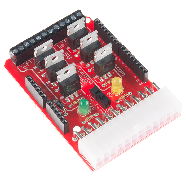
SparkFun Power Driver Shield Kit
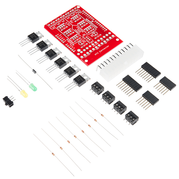
This shield allows you to use a computer power supply (or other power source) to use your Arduino to switch high current. With RFP30N06LE MOSFETS, you can easily control a lot of current directly from your Arduino.
The board provides six PWM outputs via screw terminals. Check the datasheet for the MOSFET below for full specifications on how much current this board can handle. This board is a very easy way to start using MOSFETS for your next high current project.
A protection diode has been added to the power input of this version of the board.
Note: If you want to stack another shield on top of this one, you will want to double-up on the stackable headers to clear the MOSFETs.
- Schematic
- Eagle Files
- Datasheet (RFP30N06L)
- GitHub
SparkFun Power Driver Shield Kit Product Help and Resources
Core Skill: Soldering
This skill defines how difficult the soldering is on a particular product. It might be a couple simple solder joints, or require special reflow tools.
Skill Level: Rookie - The number of pins increases, and you will have to determine polarity of components and some of the components might be a bit trickier or close together. You might need solder wick or flux.
See all skill levels
Core Skill: DIY
Whether it's for assembling a kit, hacking an enclosure, or creating your own parts; the DIY skill is all about knowing how to use tools and the techniques associated with them.
Skill Level: Noob - Basic assembly is required. You may need to provide your own basic tools like a screwdriver, hammer or scissors. Power tools or custom parts are not required. Instructions will be included and easy to follow. Sewing may be required, but only with included patterns.
See all skill levels
Core Skill: Electrical Prototyping
If it requires power, you need to know how much, what all the pins do, and how to hook it up. You may need to reference datasheets, schematics, and know the ins and outs of electronics.
Skill Level: Rookie - You may be required to know a bit more about the component, such as orientation, or how to hook it up, in addition to power requirements. You will need to understand polarized components.
See all skill levels
Comments
Looking for answers to technical questions?
We welcome your comments and suggestions below. However, if you are looking for solutions to technical questions please see our Technical Assistance page.
Customer Reviews
4.3 out of 5
Based on 4 ratings:
2 of 2 found this helpful:
Works great for my HO trains
I purchased these shield to change the direction of the switch tracks (also called turnouts) of my HO trains under DCC control using an Arduino as a DCC decoder. Instead of a PC supply, I used a 20 volt DC laptop supply. Since 20 volts is a bit high for the input to the Ardunio, I replaced the diode with a 12 volt voltage regulator. Everything works great. I finally have full control over my switches via DCC. Each shield controls three switches.
0 of 1 found this helpful:
Great!!
Worked like a charm, bought two more
Made my twinkling 12v light project work perfectly thanks.
Limited use, but working.
I am using one of these to drive 6 10ma LED's on each channel at 5V. Its hardly a test, but it is working. This ended up being about the same price as I spent on a homebrew shield. Its neater and was easier to put together.
I had to work out that this could be used at 5V on each side. It was not clear to me. Like many products Sparkfun, it could use a bit more documentation. I feel that the docs are written for the use of the people who designed the product. For me, a row of screw connectors would be more useful.
The schematic is incomplete. It would be very helpful if it showed all the devices, such as the diode, and pinouts. There is a little more guess-work than I'm comfortable with.
Hi Martin - I'm pretty sure the schematic is complete; it's what the PCB is generated from. There are multiple diodes (2 LEDs and a 1N4001) on the schematic. Which one are you concerned about?
Stupid question: Where are the instructions for putting this together? Bought the kit, need to build it. Do I have to guess which component goes where? The Datasheet is for the MOSFET, not the shield. Is it in the EAGLE files? If not, where?
Thanks ...
Not a stupid question - we should probably write a full hook-up guide for it. In the mean time M-Short is dead on: if you can follow the silkscreen go for it. If you run into problems let us know.
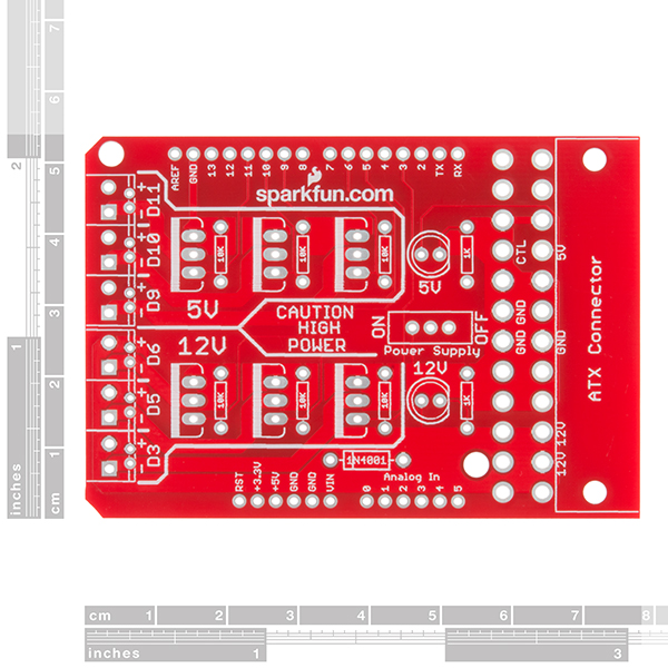
For the most part the silk screen on the PCB should tell you where everything goes. Between that and the picture of the finished product you should be able to put it together. If you have any other questions please email techsupport@sparkfun.com
Alright, this is going to seem like a weird question, but the package that had this kit in it went through a snowblower. Fell out of a jacket pocket into a snow birm, and well you can figure out the rest. Luckily i found the board unscathed, but not much else lol.
Anyway, i have a bunch of these lying around-
http://www.irf.com/product-info/datasheets/data/irfz46n.pdf
I know they lack the internal diodes compared to the rfp30n06l's, but is there any way to use them, along with external diodes as replacements?
I have everything else, the resistors, led's, 1n4001, just wondering if i can use the mosfets i have, along with some external diodes (any idea what rating if so?) in lieu of ordering replacement mosfets.
Or should i just spend the few bucks to get new replacement mosfets?
Can i get beefier mosfets of the same internal diode configuration to switch higher currents/voltages if so? Does that require different rated resistors, and a different diode than the 1n4001 if so?
I see there is no back EMF diodes across the mosfet control pins, meaning this wouldn't be able to be used (without adding our own diode) to control coil type applications, such as solenoids and relay coils, correct?
The back EMF diodes should be as close to the relay coil as possible. Although it is always a pain to have to add diodes at the relay, that is the best way. Even if the relay is only 6 inches away from the mosfet driver, it is still better to have the diode at the relay.
Take a look at the datasheet: diodes are in the MOSFETs, just inside.
Those diodes are not Back EMF diodes. Those diodes protect the FETs. machadolab is asking about back EMF diodes, to dissipate the Back EMF that relays and solenoids produce. This board does not have those.
Quick question, would this work similarly to a power FET switch that's optically isolated? this might be a stupid question but I'm new to circuitry
Can I switch multiple LED strings, that each has its own constant current source?
Is it possible to bridge two or more FETS together to increase the handled switching power?
I want to control the brightness of a LED strip approx. 100Watt (12V) with an Arduino using PWM.
Thanks!
I'm a little confused. All of the literature says the driver itself goes up to 60 volts, it the board's schematic only shows 5 and 12.
Can it go higher?
EDIT: spelling
What gauge (American Wire Gauge, AWG) of wire are the screw connectors rated for? I'm looking for the largest gauge, but I've noticed that screw connectors are rated for a range. Awesome products! Thank you!
I'm sure this board is useful to many however it defies me that no one - including Spark Fun - makes a shield using P channel MOSFETs in a high-side switch configuration. That would be SOOOOO useful for so many projects. I find myself having to always build a temporary breadboard whenever I need a high-side switch which seems like most of the time - especially for implementing dimmers for lighting that already exists in a device (like an automobile or other vehicle).
Can you guys please do a high-side version of this? That would be awesome!
i concur!! wtf is with the dearth of real high-side, high power (>> 1A) drivers? it's weird. not just sparkfun.
my favorite power driver chip is the STelectronics VN series (VN02, VN920, etc), 5 - 30 amp, CMOS logic in, 30+V, high side, inductive back EMF-eating, current-monitoring, reverse-battery protection, milliohm output, etc etc. alas, as the auto industry mutates to higher voltages and lower currents for things even these grow scarce. they drive the nastiest loads without a complaint. short-circuit proof too. i've been using the 5-pin "TO-220" packages but there's SM parts too. i keep thinking i should lay out a board for them myself. i may have to.
a board with 8 of these (on a SR or not) would be great.
Thanks!
I have a question, if I were to use all six of the outputs, how many power will i get? Or, how many volts and current? sorry i am very very new to MOSFETS.
Could I use this to power some motors? I have 4 two-phase stepper motors which I would want to run, and this is way cheaper than buying a hulking motor driver...
Am I just messed up, or is there a reason why no one has commented that this board switches the ground connections, not the power connections... or did everyone else already know that? At least that's certainly how I read the schematic and my voltmeter is telling me that ground on my "load" is way above what it should be...
Since 3 mosfets are controlled by 12v and the other 3 are controlled by 5v per the atx connector. Would it be ok to jumper the 5v line to the 12v so that all 6 mosfets run off a common 12v supply? Yes i will not be using a PC power supply just an atx connector to break the wires out.
To the question about having +12vdc on all outputs. Instead of placing the ATX power supply connector, I ordered hard disk power cable connectors. I cut the +5vdc wire, leaving the pin in place for stability, added a wire to the +12vdc pin on the connector. The other end of the +12vdc wires I soldered to the driver board, on the +5v and +12v dc holes. I still utilized the enable switch for the ATX supply, convenient. Works great. Might want to change the +5vdc LED to Yellow.
Where can we get heatsinks for the mosfets on this board?
I have that same question. I'l like to use a pair of these shields linked together to drive a single serious motor (3hp). But that means I'm going to have to dump more than 7amps through each one.
If I wanted to redesign this board using pins 6,7, and 8 instead of 3,5, and 6 would this cause any issues? I'm assuming that there wouldn't be any issues but I just wanted to double-check with the community here. I'm asking because I want to use this shield with the Mux Shield but the Mux Shield uses pins 2,3,4, and 5 and as you can see there is an overlap with pins 3 and 5. Any help would be much appreciated!
I've done this, not a problem. I would cut the traces at the connector end and at the RESISTOR end, but not between the resistor and the gate. I've bridged wire wrap wire from the Arduino connector to the resistor and to the Gate pin on the FET as well with success. Just don't forget which pins control which FET. Good luck!
Is there any way to convert it to output 12V on all 6 terminals whitout frying my Arduino? I bought it thinking that it was sending 12V out on all 6 terminals and only using 5V to power the Arduino :(
I found out that frying your Arduino won't be an issue, since the shields sends no power to the 5V pin. Instead it feeds 12V to the VIN pin. So to get 12V on all the outputs, you just have to send 12V to the ATX pin marked 5V also.
The board only uses one of the 5V pins, so that will limit the maximum current on the "5v" side
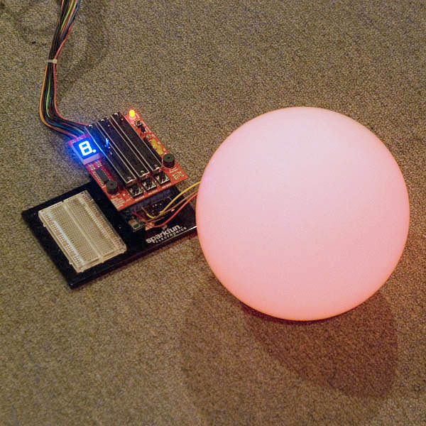
Any reason why there's a picture of the Danger Shield being used in the product pictures area? :P
Because the Danger Shield is placed on top of the Power Driver Shield.
"Check the datasheet for the MOSFET below for full specifications on how much current this board can handle."
Really? The datasheet says each transistor can support continuous load of 30 A. However, the previous version of this product was (according to its comment log) limitted to ~8 A per transistor by the board traces. Have they been massively increased in cross-section in this revision?
Also, the best guess I can make for the screw terminals (link from a related item that has a part list) is that the terminals are rated for 6 A.
It's the lowest component current rating of the entire circuit that sets the circuit's rating. If my inferences are correct, the instruction to get the current rating from the datasheet gives one a factor of five error.
Eric
what about the standby power pin and control pins?
can the Arduino run off the supply when its off, and start the PSU up on-demand?
hmm, from looking at the schematic, the standby power doesnt go anywhere
and its using a mechanical switch to turn the PSU on, so the Arduino cant control that
Powering the Arduino from ATX standby power is a definite maybe. The ATX standby power is specified at 10 mA, but that's a minimum value and many ATX power supplies provide considerably more current. So it depends on what your ATX power supply provides and how much power your Arduino application needs.
The ATX power supply control pin is specified as an open collector input. You should be able to use one of the power MOSFETs to connect to the ATX control pin to ground it on command from the Arduino. This could be done in parallel with the mechanical switch.
Any quick info to add to the description as far as max dissipation/max current? Min/max voltage?
Might be a good idea to put a heatsink in the related products, for those interested in a little more power.
Without a heat sink and at 24C ambient temperature, the maximum current through each MOSFET would be about 6.3A at a junction temperature of 175C (ouch!). It'd be a good idea to stay well below this limit. Keeping the current below about 3A would be reasonable because the MOSFET will remain cool enough that you won't get burned if you touch it.