- Home
- Product Categories
- Audio Boards
- SparkFun FM Tuner Evaluation Board - Si4703

SparkFun FM Tuner Evaluation Board - Si4703
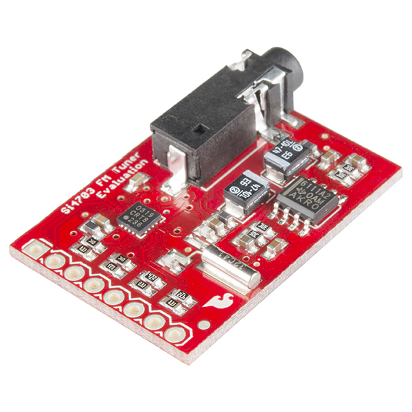
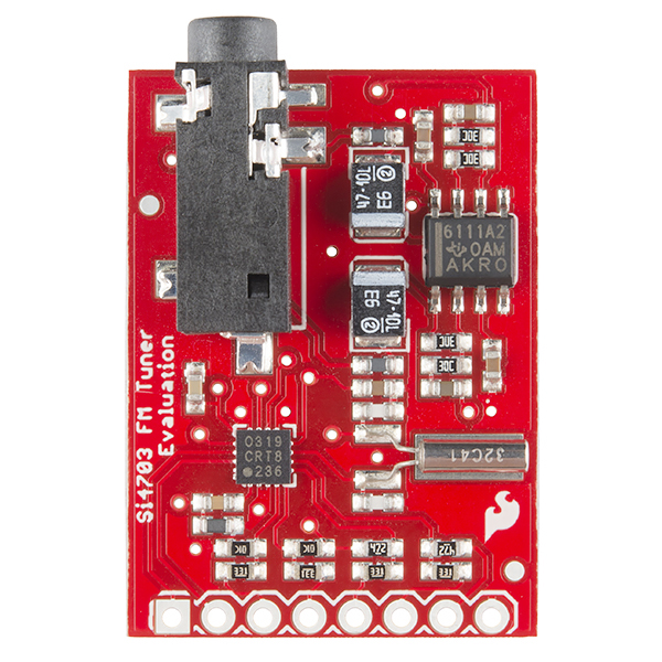
This is an evaluation board for the Silicon Laboratories Si4703 FM tuner chip. Beyond enabling you to tune in to FM radio stations, the Si4703 is also capable of detecting and processing both Radio Data Service (RDS) and Radio Broadcast Data Service (RBDS) information. The Si4703 even does a very good job of filtering and carrier detection. It also enables data such as the station ID and song name to be displayed to the user.
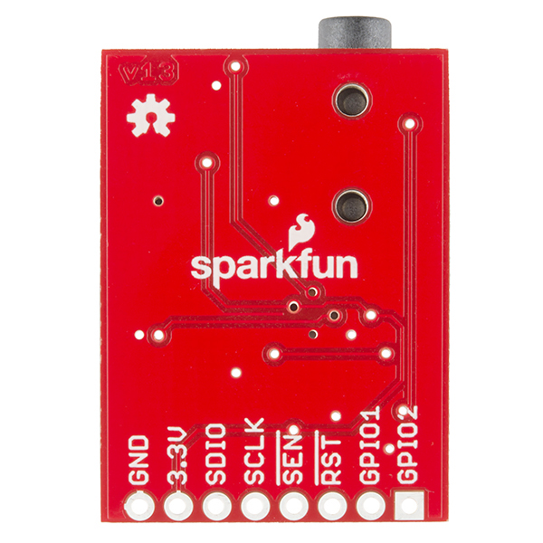
Using this board, you will be able to pick up multiple stations just as well as with a standard FM radio. The board breaks out all major pins and makes it easy to incorporate this great chip into your next radio project. The power bus, the 3.3V and GND pins are broken out For communication. The breakout provides access to SDIO and SCLK for I2C communication while RST can be used for easy resetting. The SEN pin enables the user to change the mode of functionality of the IC. The last two pins broken out are GPIO1 and GPIO2 which can be used as general input/output pins, but also can be used for things like the RDS ready, seeking or tuning functions.
Keep in mind, by plugging headphones into the 3.5mm audio jack, you effectively use the cable in your headphones as an antenna! Therefore, this board does not require an external antenna if using headphones or a 3.5mm audio cable longer than 3 feet.
- Schematic
- Eagle Files
- Datasheet (Si4703)
- Datasheet (AN243)
- Hookup Guide
- GitHub (Library, Example Code, & Design Files)
- Product Video
SparkFun FM Tuner Evaluation Board - Si4703 Product Help and Resources
Si4703 FM Radio Receiver Hookup Guide
August 13, 2015
Add some tunes to your project with the Si4703 FM Radio Receiver Breakout.
Core Skill: Soldering
This skill defines how difficult the soldering is on a particular product. It might be a couple simple solder joints, or require special reflow tools.
Skill Level: Noob - Some basic soldering is required, but it is limited to a just a few pins, basic through-hole soldering, and couple (if any) polarized components. A basic soldering iron is all you should need.
See all skill levels
Core Skill: Programming
If a board needs code or communicates somehow, you're going to need to know how to program or interface with it. The programming skill is all about communication and code.
Skill Level: Competent - The toolchain for programming is a bit more complex and will examples may not be explicitly provided for you. You will be required to have a fundamental knowledge of programming and be required to provide your own code. You may need to modify existing libraries or code to work with your specific hardware. Sensor and hardware interfaces will be SPI or I2C.
See all skill levels
Core Skill: Electrical Prototyping
If it requires power, you need to know how much, what all the pins do, and how to hook it up. You may need to reference datasheets, schematics, and know the ins and outs of electronics.
Skill Level: Rookie - You may be required to know a bit more about the component, such as orientation, or how to hook it up, in addition to power requirements. You will need to understand polarized components.
See all skill levels
Comments
Looking for answers to technical questions?
We welcome your comments and suggestions below. However, if you are looking for solutions to technical questions please see our Technical Assistance page.
Customer Reviews
4.7 out of 5
Based on 6 ratings:
1 of 1 found this helpful:
Si4703 FM with Micro OLED Display Review
I've been looking at this FM tuner board for a while and considering its use for adding FM capability to an old automotive AM tube radio (long story). One of the things I was looking into was how to display the frequency information without detracting from the look of the AM radio when the FM tuner is turned off. Shawn's post using the Fio v3 and micro OLED display inspired me to recreate his project using an Arduino Pro 3.3V, 8 MHz (since I didn't need the battery capability).
I integrated the SparkFun FM Tuner Evaluation Board and Micro OLED Breakout v1.0 with the Arduino Pro using the hookup guides for the 4703 and OLED display from the SparkFun site. I added a SPDT, center-off toggle switch to handle up/down inputs, and a SPST momentary pushbutton used to select the different control modes.
I placed the Arduino code for this in GitHub, with the Required library - Si4703_Breakout_Modified. From Shawn's video, I think I have all of the functionality covered for the Fio device he demonstrated (minus the battery, of course). I also added a couple of modes of RDS display to the code as this was something I wanted for my car radio application.
To make the RDS work the way I wanted it to, I chose to modify the Si4703_Breakout Arduino library that the SparkFun hookup guide uses. I included the modified library, Si4703_Breakout_Modified, on GitHub as well. The changes are mostly around the readRDS routine, but I also made one of the private functions from the library into a public function so I could call it directly from my code.
I'll post some pictures and possibly a video demonstrating how this thing works when I can get around to uploading them. The UI is different from Shawn's demo, but again I was tailoring it to what I want in the car radio.
The Si4703 Board and the Micro OLED display Boards work beautifully! I plan to integrate the OLED display into all kinds of projects now that I've been able to play with one. As an aside, since I hooked up both boards in this project per the SparkFun online hookup guides, all of the demo code for each board will run on the combined assembly. This means that the Arduino code for this project can be easily modified to display an analog clock, mini-pong game, or rotating cube as a screensaver display instead of the RDS and frequency information I am currently displaying. Just a thought...
1 of 1 found this helpful:
Works great!
This looked like a fun gadget to hook up to a raspberry pi. Was able to find example code online to get it started up quickly and now I just have to fine tune how I want it to work.
1 of 1 found this helpful:
Works well
To use an antenna, solder the last pin on the edge facing side. I wish there were an FM/AM version available for this.
Best Find
I'm designing a Tophat for Halloween and I wanted a radio to play out it. This does the job. Next time I'll make sure to buy a logic level converter so I don't destroy the IC.
Works well!
It worked great on headphones, the only thing I would have liked is a tutorial on how to add your own antenna to this board. I'm using it on a Raspberry Pi and won't be using headphones. I wrote a Node JS wrapper library to control it through i2c on a Raspberry Pi: https://www.npmjs.com/package/node-rpi-si4703
Surprisingly good tiny receiver
Delivers excellent reception and solid audio output. Worked right away with RPi (after I remembered to drive the RST input--this is not optional!) It would be great to see the simpler version, "SparkFun FM Tuner Basic Breakout", back in stock, which would fit my use case a little better: yes: antenna terminal, no: headphone amplifier.
Does anyone know if the Arduino library has been ported to Python? Thanks in advance.
a question, I have to extract the TA AF PTY signals from to RDS ... The used library is this: 1-6-2011 Spark Fun Electronics 2011 Nathan Seidle, the names of all the registers in #define are visible, how can I do ??
Any suggestions on how to determine the current power state?
The enabled bit resets to 0 after power up, and the disabled bit resets to 0 after power down.
My apologies, I was looking at the wrong bit. Turns out the enable bit is a perfectly good bit to use to determine whether the Si4703 is powered up or down.
Can you run this off of 5V instead of 3.3v? The specs for the FM receiver and the audio amp say that 5V is OK. Adding 3.3v logic level converter is a bit of a hassle when everything else in the system in 5V and the parts are 5v capable. I'm going to be connecting it to a SparkFun RedBoard which is 5V.
Per my understanding, no, you should not connect it to 5V.
rereading the specs again - Interface voltage Vio is 3.3v. Yep, that would be the problem.
What can be done to eliminate the popping sound when enabled?
.
Can someone confirm that FM frequency is set as a three-digit integer (ie 99.5FM would be 995)? In the Hookup Guide it shows channels like 996, or is that for non-US radio frequencies?
Yes, 995 would be used to tun to 99.5.
Is there any chance we can get the Si4777 on a board? I want HD radio and don't have the equipment to solder SMDs (so far I can only find the bare SMD chips for HD).
We don't have plans for a Si4777 breakout board unfortunately. Even if we did, the licensing costs associated with HD radio would probably make a breakout cost somewhere north of $100. Until the company that owns the patents on HD radio releases details on how to decode their CODEC without paying a fee, you're never going to see a HD radio receiver in the hobby electronics world.
Isn't the decoding done on the chip itself? Wouldn't the licensing then be handled by the chip manufacturer?
No, the decoding is done by a HD radio processor chip that has a CODEC for decrypting the HD stream you're receiving. They have to pay a license fee to iBiquity (the folks that own the HD radio CODEC) to make the chip, and chip manufacturer then pass that fee onto anyone that buys the decoder chip. You end up paying the fee when you buy the chip.
My embedded programming is pretty bad – would it be possible to adapt the library for an ATtiny 85?
In theory yes. I would start by looking for an addin to allow the Arduino IDE to compile for the ATtiny85. The IDE already lets you program using an AVR programmer so you would just need to hook that up. The only other issue is memory. Make sure the code will actually fit on the ATtiny85. Basically though once you get the IDE to compile for the ATtiny85 you should be good to go.
Thanks M-Short! I've compiled lots of things for ATtiny chips in the past, but I think the interrupts etc are different. The library wouldn't compile for me for ATtiny, but not because of memory I don't think.
Yeah, two months of (sporadic) work later and it doesn't look easily possible. It would take some doing, but could be achieved with the TinyWireM library + some mods on the Sparkfun lib.
Could the board be powered by a lithium polymer battery by any chance? The datasheet for the chip itself says the max voltage is 5.5 volts for digital and analog supply, however the max for interface supply indicates 3.6 volts. That max is 0.1 volts under what a li-po battery provides. So will it fry the ic?
It's not recommended. A better set up for you would be to use a 3.3V Pro Mini as the communication and power interface with this board, and then hook the lipo up to the Pro Mini, which will regulate the power properly.
Is it possible to bypass the amplifier? I have this board but want to integrate it with a bluetooth audio board so I'll need to use a separate amp. I'd prefer to make use of this breakout board, since I have it lying around. Thanks!
You certainly could bypass the amp, but you'll probably need to cut the traces to the amp and solder jumper wires onto the break out board. I'd recommend taking a look at the Eagle files to see where the best bet would be for cutting those traces. Keep in mind you'll need to scrap away the solder mask on the traces to solder additional wires on there.
While not exactly the details of Shawn's hack, I posted a link to some code with (I think) the same functionality that Shawn demonstrates in his video in a review I just posted.
The chip keeps getting struck in radio.init(). In example, it prints "init" in "setup()" function but does not go to "void loop ()" main program. Any suggestions to diagnose or known issue?
Make sure you have the board hooked up correctly, specifically the I2C lines as the pins change depending on the microcontroller. If you are still having problems try emailing techsupport@sparkfun.com.
Which Li-Po battery does Shawn recommend for the FM Stick?
That's a really cool little portable FM radio that I will be looking into building if my old house ever sells and I can spend money at Sparkfun again. After I get back from two weeks in Scotland with my wife, that is.
Where can I get that small rocker switch you use in the video?
This guy should work.
No, I meant the rocker/pushbutton switch used for display selections.
Looks like this.
Yep, that's the one. Also available on a breakout board
that's it. Thanks.
OK, I'm guessing Shawn was listening to "Light my Fire" by the Doors.
OH and PLEASE put the details of Shawn's hack on line including the hookup with the two or three other boards he used and the source code.
Is the code for the FM Stick available?
Apparently not here.
Has anyone used this to decode time from a RDS signal?
I read that it's actually quite rare for stations to transmit RDS time. Obviously, YMMV based on your location and your radio stations.
What if I wanted to use an external antenna?
If you wanted to do that you should look at https://www.sparkfun.com/products/11083 it breaks out the antenna pin. Based on the schimatic, I assume this board expects the headphone wire to be the antenna.
Yep. This one uses the headphones as an antenna, for better or worse.
sorta off-topic, but whoa, that is one small LCD from that example video! Do you guys carry that LCD?
Heck yeah! This is the breakout that Shawn used in the video. It is the same OLED that goes into our MicroView module.