- Home
- Product Categories
- Stepper Motor Driver
- Big Easy Driver

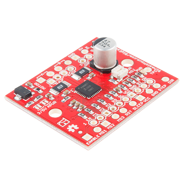
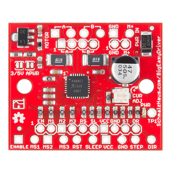
The Big Easy Driver, designed by Brian Schmalz, is a stepper motor driver board for bi-polar stepper motors up to a max 2A/phase. It is based on the Allegro A4988 stepper driver chip. It's the next version of the popular Easy Driver board.
Each Big Easy Driver can drive up to a max of 2A per phase of a bi-polar stepper motor. It is a chopper microstepping driver which defaults to 16 step microstepping mode. It can take a maximum motor drive voltage of around 30V, and includes on-board 5V/3.3V regulation, so only one supply is necessary. Although this board should be able to run most systems without active cooling while operating at 1.4-1.7A/phase, a heatsink is required for loads approaching 2A/phase. You can find the recommended heatsink in the related items below.
Note: This product is a collaboration with Brian Schmalz. A portion of each sales goes back to him for product support and continued development.
- Bi-polar Microstepping Driver
- 2A/Phase Max
- 1.4-1.7A/Phase w/o Heatsink
- Max Motor Drive Voltage: 30V
- On-board 5V/3.3V Regulation
Big Easy Driver Product Help and Resources
Big Easy Driver Hookup Guide
February 13, 2015
How to get started with the SparkFun Big Easy Driver.
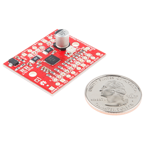
Board Dimensions
Measuring with a caliper, the board dimensions are approximately:
Width = 30.94mm
Length = 37.34mm
Height = 1.71mm (bottom of the PCB to the top of the capacitor 9.7mm)
Damaged Driver?
The development/breakout boards that are produced by SparkFun are usually tested on a pogobed https://learn.sparkfun.com/tutorials/constant-innovation-in-quality-control and inspected by a technician for quality control before they are packaged and sent out. This reduces the chance that a bad board was sent out.
If you had a loose connection or a bad power supply and the stepper motor is not running (after checking the power supply, potentiometer, example code, and connections to your microcontroller), it's possible that the driver was damaged. If you are able to move the stepper motor's shaft and the board's IC or GND plane gets extremely hot to the touch, the board might have been damaged. In extreme cases, the IC blows out from having a loose connection.
Solder Joints
Make sure that you have good solder joints. Any loose connections between your stepper motor and the channels of the stepper motor driver can damage the IC. In general, if there is a loose connection when the coils of the stepper motor are energized and connected to the channels, there will be feedback that will fry the stepper motor's IC.
Heat Sink Recommendations
You do not need a heat sink to get the board working with the 68 oz.in or 125oz.in stepper motor. We have been able to get it working without the need to add a heat sink. The ground plane on the back of the board is sufficient to get it working. The board would get hot to the touch but it was able to run without any issues. It might be recommended for long-term use so that the IC will not be damaged from the excessive heat and have it run more efficiently.
Humming/Buzzing Noises and Stepper Motor Not Moving?
You might need to adjust the potentiometer to provide more power to the stepper motor. There is a current adjustment potentiometer that would be the best to allow more current to the stepper motor. The stepper motor should be able to run more smoothly (assuming you have enough power from your power supply) after adjusting the potentiometer. You would need a precision, flat head screwdriver. Make sure to adjust the potentiometer slowly. Applying too much force and turning it too much can damage the component. It does not take much to damage the potentiometer.
Power Supply Suggestion
Make sure that your power supply is stable. Unstable power supplies will cause the stepper motor driver to blow out. The ripple and spikes in voltage can cause the IC to work harder and will blow out from the feedback.
Compatible Stepper Motors with Example Code
The Big Easy Driver was able to work with the 68 oz.in and 125oz.in stepper motor. Testing it with a variable benchtop power supply at 9V/2A, I was able to get it working with both the old bildr turorial's example one_stepper_example.ino provided in one of the old bildr tutorials http://bildr.org/2012/11/big-easy-driver-arduino/ and the example code that was provided in the SparkFun hookup guide => https://github.com/sparkfun/Big_Easy_Driver/blob/Hw-v1.6_Fw-v1.0/Firmware/SparkFun_Big_Easy_Driver_Basic_Demo/SparkFun_Big_Easy_Driver_Basic_Demo.ino . The maximum that we saw the power supply pull was around 1.9A briefly when the potentiometer was adjusted to the maximum current.
Note: You must send numbers through the serial terminal in order to move the stepper motor with the SparkFun example code. Also, both example codes use different pin connections so make sure you are connecting the board to your Arduino correctly.
Core Skill: Soldering
This skill defines how difficult the soldering is on a particular product. It might be a couple simple solder joints, or require special reflow tools.
Skill Level: Competent - You will encounter surface mount components and basic SMD soldering techniques are required.
See all skill levels
Core Skill: Robotics
This skill concerns mechanical and robotics knowledge. You may need to know how mechanical parts interact, how motors work, or how to use motor drivers and controllers.
Skill Level: Competent - You may need an understanding of servo motors and how to drive them. Additionally, you may need some fundamental understanding of motor controllers.
See all skill levels
Core Skill: Programming
If a board needs code or communicates somehow, you're going to need to know how to program or interface with it. The programming skill is all about communication and code.
Skill Level: Rookie - You will need a better fundamental understand of what code is, and how it works. You will be using beginner-level software and development tools like Arduino. You will be dealing directly with code, but numerous examples and libraries are available. Sensors or shields will communicate with serial or TTL.
See all skill levels
Core Skill: Electrical Prototyping
If it requires power, you need to know how much, what all the pins do, and how to hook it up. You may need to reference datasheets, schematics, and know the ins and outs of electronics.
Skill Level: Competent - You will be required to reference a datasheet or schematic to know how to use a component. Your knowledge of a datasheet will only require basic features like power requirements, pinouts, or communications type. Also, you may need a power supply that?s greater than 12V or more than 1A worth of current.
See all skill levels
Comments
Looking for answers to technical questions?
We welcome your comments and suggestions below. However, if you are looking for solutions to technical questions please see our Technical Assistance page.
Customer Reviews
4.4 out of 5
Based on 41 ratings:
1 of 1 found this helpful:
The Big Easy Review
Very easy to use. All pins are clearly labeled. Set the voltage to 3.3V... connected a microprocessor and wrote a quick control routine. Powered up the unit and adjusted the current up until the motor was stepping. I was able to prototype a project in short order. Thanks.
4 of 4 found this helpful:
Worked well
It worked fine on first try. It does get very warm when using it with the 57BYGH420 (125 oz-in 2 amps per phase) stepper motor - even with the added heatsink.
There is an error in the sparkfun Big Easy Driver Hookup Guide. On page three the MS1 through MS3 pins are specified as having 100K pull down resistors. In fact it has pull up resistors. Thus if these lines are left unconnected the default step mode would be sixteenth step - not Full step (as it would be if the resistors really were pull down instead of up).
5 of 5 found this helpful:
Beware the heatsink!
The product itself seems to work great, but be very careful about placing the recommended heatsink should you need it!
I had the heatsink square on the IC, but being a little larger than it probably should be this places it overhanging the (relatively) high voltage resistors near the coil hookups. It ran fine like this at 12V, but as soon as I took it to 24V I got a nice lightshow as it arced through the heatsink and into the IC.
Sparkfun was great about it and offered to replace it for me, so all is well, but I wanted to make sure that people are aware that this can happen. When the replacement comes I'll make sure to bias it towards the low voltage resistors.
1 of 1 found this helpful:
Big Easy Driver - yes it is
The Big Easy Driver (v1.2) is exactly that. Use the sketch from GitHub, or from the original site. Used 12vDC source (wall-wart style) and coaxial-M jack to provide power for the driver. Works well with even a smaller stepper that is/was included in the RadioShack Motor Pack for Arduino. This stepper (2730767, 5VDC, 1:64) is a bit non-standard, but is a bipolar configuration with the two coil-centers joined as pin 5. Color coding seems non standard, but resistance testing verifies the proper set of 4 pins for attachment to Coil-A and Coil-B on the Big Easy. Adjusted drive current to minimum, anticlockwise rotation to reduce heating of the stepper motor. The Big Easy is, and runs COOL.
1 of 2 found this helpful:
Worked really well for a little bit
I had the exact same experience as Member #408477 below, I just wish i had read his/her review first.
Got it up and working with a knock off Arduino Leonardo in short order, and ran it off a computer power supply at 12v to test with a small nema17 motor. I but the heat sink on, connected to my larger Nema 23 Motor and connected a 24V power supply. using the test sketch, Motor ran one direction and then right as it started to run the other way, I got a nice bright flash and smoke. It appears it shorted out to the high voltage side nearest the large capacitor. That was a short lived $20...
BEWARE - If you use the recommended heat-sink, PLEASE keep it away from the output side of the IC.
0 of 2 found this helpful:
Junk
Did not work.
I'm sorry your device didn't work for you. We would love to get more information on your case and help you if we can. Please contact our support team for further assistance.
Pretty Amazing Little Guy!
This is my third BED and I am just as impressed as always! Easy to use, very handy indeed. I love the potentiometer so i can use it with a variety of steppers. I'm sure I'll be buying a few more in the future. I would recommend this to anyone looking to drive a stepper motor for your project.
Works well
I ordered this to replace one that I had ordered last Fall, but had been damaged.
Great Driver; Works Well for Stepper-Controlled Needle Valves
We are using a these to control a stepper motor attached to a needle valve. The drivers work great and are exactly the same design & components as another (branded) driver. The jumper vias are super-useful when you want to stack and mount the boards (as we did).
Fantastic board!
I'm able to use the driver in a 33C environment without having to worry about it overheating.
0 of 1 found this helpful:
not working
I have not been able to get it to work
Sorry to hear that. These are usually rock-solid. If you contact our tech support team, they should be able to help you get it straightened out.
No problems! Works perfectly as described. Would be nice to add a heat sink easier though.
works great and sparkfun is awesome
i bought these for my first robotics project ever. i was able to get them up and running fairly easily with all of the resources available on sparkfun and elsewhere online. sparkfun customer service has also been awesome for me.
Worked great right off the bat
I'm using this with the 125 oz/in stepper that is available on Sparkfun and while the driver worked great from the start it does get quite hot. I got the heat sink for it and I highly recommend that if you're using a bigger motor.
Also, do yourself a favor and get the screw terminals. I just soldered some pins in and started experimenting with my motor. That worked just fine until the whole contraption was dragged off the table by the motor that had vibrated to the edge. In the process some of the wires may have gotten pulled a little loose, the end result being that it looks like I killed the driver.
Addendum: As it turns out I didn't kill the driver but I would still recommend getting the screw terminals. At the very least, don't solder your pins on in the downward position thinking that you'll be able to plug it into a breadboard. The overhang needed for the screw terminals causes at least one side to cover all the remaining holes on a standard 5-hole row.
Another Addendum: Be very careful about back driving current. I have a stepper hooked up to a 45:1 gear box that is driving a collet holder. When I attempted to tighten down the collet I didn't think about the fact that the motor might be driven and when it spun fast for a moment I instantly heard a pop and saw smoke coming out of the driver.
Easy to use and works great!
Wiring two of these up to an xy table (WaveDynamics from eBay), controlling with Arduino at the moment but may switch to a faster system (MicroMite or CUI32Stem) if I need to. These driver boards are elegantly simple to use - well done Brian Schmalz!
Great little board!
We're developing a stepper motor driven valve positioner. Our first scan for available driver boards located ones way too big and way too expensive. Then we found the Big Easy board. Perfect size and cost. We popped two of them on our breadboard until we finally wired it correctly - our fault but it didn't cost an arm and a leg and now we have it running smoothly. This will definitely be in the BOM for our new product.
some day I may love this driver
I'm still trying to make it work with the Parallax BS2
Hello!
Have you contacted our technical support department @ techsupport@sparkfun.com - they're usually pretty good at figuring out compatibility issues and getthing things to work.
Only worked for a few seconds.
I wired 12V to the board when I first got it to see if it worked and the light came on for a short amount of time and then turned off. I then connected my stepper motor (https://www.sparkfun.com/products/10846) to see if it was just the light that was broken, but even with the sparkfun arduino example the servo did not spin. This leads me to believe that the board is broken. If anyone has a fix or an idea of what component is bad please let me know.
Sorry to hear about the issues with the Big Easy Driver.
Contacting our technical support department at techsupport@sparkfun.com is the best way to get help with troubleshooting your device. They're really good at helping figure out what's going on.
It's a beautiful thing
worked perfectly, well documented, and it has effective current control. beats the pants off the (several) L298 based drivers i have tried. I will definitely be buying more of these
Very smart controller!
The A4988 chip is a very smart stepper driver where you only need to set the DIR pin and STEP it. The driver board I had been using was just a dual H-bridge, requiring the MCU to manage all the stepping phases with two pins plus a current-controlling PWM pin for each coil. And the available libraries aren't nearly as competent at current control as the A4988 chip. This driver also eliminates the hum/noise that can occur from the Arduino PWM frequency controlling the H-bridge current!
The hookup guide over-complicates things by connecting 6 control lines and then virtually ignoring all but DIR & STEP. (The others can remain unconnected!) You'll really want to look at the schematic, data sheet and designer's site to fully understand and appreciate the board. For example, the low/high pulse width for STEP only requires 1µs, not the 1ms in the sample code. (Off by x1000!)
Ultimately the Big Easy Driver is actually quite simple to use and drives a stepper with a very efficient and effective waveform!
I would like to see the layout tightened up a bit (e.g. eliminate the doubled connection pads) and the board size reduced. But it's an excellent product!
very good
good quality, good operation, good examples
Great product!
The Hookup Guide associated with the Big Easy Driver was incredibly helpful and made it very easy to get up and running with my bipolar stepper motor. I added a heat sink because I am pulling close to 2 amps per phase as per the documentation. Very pleased so far!
lives up to its name (the easy part, not so much the big part)
Very simple to use, and good documentation.
Worked perfectly
When I started to lay out a stepper board I chose the A4988 for its ease of use, however I found that it was only offered in the dreaded "Q" package. Then I found the Big Easy. Great form factor and I can lay out four on my driver board and they are still small enough to fit nicely. Good documentation and all the right pins brought out. Great job! Fritz
Works great
I have yet to put it through all it's paces but my initial impressions of the driver is very positive.
Good Product
After much research, I decided on the Big Easy Driver. The one thing that I didn't like about the board is the A+, A-, B+, B- isn't clearly marked on the board, (Just the two holes grouped together as A and the other two holes grouped together as B.) if you carefully read through the technical page, it was easy enough to figure out. The potentiometer comes pre-adjusted to the middle range, but most people probably will need a magnifying glass and a really small screwdriver to adjust. There are also too many connections between the Big Easy Driver and Arduino, it would be nice if they could figure out a way to streamline the connections. (Adafruit offers a board that where the board with top pins plugs into a header on the Arduino board, The step resolution 1/4, 1/2 step etc. appears to be worked out with more streamlined code.) The reason I bought this is because the board can take a higher voltage and amperage for the motor than its competitor. When I first got the board, I'm a beginner and overlooked the terminal blocks and had to go back and order them. It would be nice if SparkFun would sell the boards complete or at least offer a kit with the heat sink and terminal blocks. I'm not an electrical engineer, so if you're an average Joe and you don't know what you're doing read through the web site very carefully more than once and make sure you buy all the recommended upgrades like the heatsink.
Yes
Very straightforward. I love the fact that it just takes a rising edge and does all the fancy microstepping in the background, meaning you can now drive a stepper with just a resonator and Divide-By-N counter, or even a 555.
Mine works well, but my main complaint is this: Not all microsteps are created equal. I'm giving it pulses at a few hundred hertz, but I can clearly feel jerks at regular intervals corresponding each non-micro step.
Great product though!
This driver + Nano 33 IOT + 17HM08 = Success
Using this for a grand father clock project. Worked nicey!
Issues encountered:
-I got some very weird jumping around (like, moving a full 90 degrees unpredictably) when unloaded and using full-steps. Adding some weight and micro-stepping at a quarter fixed that.
-The stepper and the driver will get hot if you are using them continuously! Added a chip heatsink, dropped the amperage from 1.2A (rated current) to 0.9A, and programmed in a duty cycle. Fixed it, mostly.
Nice units for my project
Easy to use. Fitmy needs perfectrly.
Could not be simpler to use
I am very impressed with this driver. It could not have been easier to hook up, and write code for. I am particularly pleased with the current adjustment on the board. I was able to dial my power down to the point where the stepper motor barely runs warm, which is ideal for my project.
cannot drive full 2 amps
I tried to use it to drive a 2 A stepper motor. I installed a heat sink and used a supply with plenty of current supply. It still burned out almost immediately. Now it's just a dead short and hot to the touch when power is supplied.
It behaves
It works as designed.
works great
I am using these in a 4 axis control for a drill press in my wood shop- fence, left and right stops and elevation. I am using these with Arduino Due microcontrollers. I chose the Due because of the PWM and other features. I downloaded several libraries from GitHub and Arduino sites, modified them to better suit my needs. I am still in the development phase but the Big Easy Drivers are working very well This is my first experience with steppers motors. That said, I would recommend these for anyone wanting to use steppers.
Just works
Super simple. Using a couple to drive steppers for a white board plotter.
Works great
Using it to drive the 125oz.in SparkFun motor (https://www.sparkfun.com/products/10847) from an Arduino Uno. Easy to assemble, set up, and use. 0 problems. Note though that the driver itself does get hot, depending on the current the motor is sinking. Can still drive this motor fine (didn't measure current but had enough juice to lift a phone book off the ground, so a few pounds), but for larger motors you may want to get a heatsink.
0 of 1 found this helpful:
Easy to broken
Bought for drive a high torque stepper motor but : 1. easy to get heated but area is too small to install heat sink. 2. Pin(B-) is not functioning after turned on by several times.
If you don't have a heat sink that fits, you can cut a piece of aluminum to fit and mount it using the mounting hole on the side of the board and some thermal tape. That would be a simple diy heat sink to fit.
Great Stepper motor driver
Works great and does exactly what is says it can do. The chip does get hot, but that's expected as I'm running a motor at about 1.5A per phase. Other than that it was really easy to set up and use with my arduino. I would definitely recommend this board as a controller if you want a simple way to control your stepper motor.
In the hookup guide is specified to use a power supply in the range 8-35V. This does not influence the minimal nominal voltage of the stepper motor to be used, yes? I've ordered a NEMA11 stepper with only 3.3V as nominal voltage and 1.5A per phase: https://www.orientalmotor.de/Products/Stepper_motors/Stepper_motors/high_torque_2phase_motors_pkp/?arid=23564
Tested! It works even with stepper with low nominal voltage (i.e. 3V). I have used a cheap chinese power supply unit (WANPTEK 0-60V 0-5A DC): voltage output = 8.5V, max current limit = 1.5 A. After slowly turning the small potentiometer on the BED the required 1.3 A was reached without problems. The stepper is also working like a charm.
Hello! I noticed the hook-up guide has a Fritzing schematics with BigEasy Driver as part of schematic. But I can't find Big Easy Driver as component in Fritzing. Is there any way to get it?
Got this board for the holidays, was testing this board out with moving a stepper, and worked well. Then I was getting higher speed by using acceleration based control. this worked well, got delay down to 600uS no problem, then reduced the delay to 400uS, ran and braked with Gcode, it spun up, and as soon as the brake was applied, a large spark sound was made, and a hole was blown into the IC chip, guess the fly-back voltage was too high. And not only did this fry the BED, it also fried my Teensy3.6.... Stepper was the 125oz. in. sold by Sparkfun.
could i use this for the M49sp-2k 7.5angle/step 6.4ohms MITSUMI stepper motor?
I just noticed this board is used in the opening scene of S1:E6 of "The Blacklist". Not sure what they needed a stepper motor driver for when building a bomb, but that's Hollywood for ya.
where does the heat sink go? thank you, thomas
Hi Thomas! A heatsink can be attached to the bottom of the board between the mounting holes if you attach a insulating sil-pad between the board and heatsink. An easier option would be to attach a heatsink like one of these to the top of the square IC in the middle of the board with some thermal adhesive.
Hello,
I have a question about running a 12v stepper motor at a higher voltage like 13.5v or 14v. Will the voltage tolerance be fine or not ? (... should I use a voltage regulator for this ?)
Thanks
It depends on the max voltage rating for your specific motor. You will need to verify if your motor can handle a higher voltage in the datasheet for your particular motor.
Not sure where to report an error in documentation. Basically the schematic lists the screw terminals as 2.5 mm pin pitch. They are however, 3.5 mm pin pitch (measured based on fit of Part #: PRT-08084.)
Good catch! You do indeed need 3.5mm screw terminals. We will get the note in the schematic corrected.
Hello! A few days ago i ordered the Big easy driver - ROB-12859 for stepper motors and also the NEMA 23 stepper motor - ROB-13656. I know that the big easy driver requires a voltage supply of 8v - 35v on the M+ motor power pin. and this stepper motor is rated at 3.2v. My question is, is it safe to use a 12v power supply in order to power this stepper motor through the big easy driver using the motor power pin (M+) ? I am concerned i might damage the motor if i am supplying it with too much voltage, or does the big easy driver regulate this voltage? If i cant do this then how would i get this motor to work if the supply needs to be within 8v - 35v ? Thanks!
Please read over the hookup guide here for using the Big Easy Driver. This should answer a lot of your questions regarding functionality and wiring, but the short answer is that you will be fine using the 12V power supply on M+. The A4988 IC will supply the power to the motor (which is compatible with the Big Easy Driver).
Thanks!
Just a "Ha ... how about that!" ...was watching "The Blacklist" Season #1 Episode #6 a guy is rigging a car to blow up with remote detonator [about 34 sec in] and includes a "RED" PC board in his "rigging". Of course when I see the Sparkfun signature red board I can't help myself .... I gotta single frame it to see if I can figure out which board it is. Sadly it's this one. I say "sadly" because it should have been an XBee, or maybe a GSM. How you would use a stepper motor driver to blow up a car I have no idea!! (Homeland Security ... please carefully re-read that last sentence .. thank you).
Hah, i just watched that episode and did the same thing. You beat me to it.
Just fried a raspberry pi 2 using 4 of these guys. Could use some advice on how to fix.
So I am building a cnc machine. I've hooked up 4 BEDs as recommend in the hookup drive. I've closed the 3v/5v jumper, and had all these working individually. Then as soon as I connected power with all 4 BED's connected it fried my RPi2.
The BEDs are all connected using a 12v 5.2A power supply. The thing is, when I disconnect everything and connect a single BED to power I see the DIR and STEP pins read 3.3v. I'm not sure why these input pins are reading high. No idea how many mA they are putting out but was wondering if the cumulative current from the 8 connections (4 DIR, 4 STEP) could have fried my board. Do I need to put a resister between the RPi2 output pins and the BED input pins? Is there something else? I don't see any evidence of shorts.
Really appreciate any help.
Information and Guessing:
[APWR] Jumper is also hard wired as shipped and enables the on board (3.3v or 5v) regulator.
[VCC] - Can be an input or output based on the [APWR] Jumper. [VCC] - Does not need to be used. [VCC] - Can only supply about 100mA. Example: Powering a Photon WIFI Dev board with the BOD. It will NOT work as it requires 400mA startup but only 100mA running.
If: You connect VCC BED to your PI
Result: The BED, has a APWR jumper that is HARD+Jumper pads that would need to be CUT with a knife.
Found: If the APWR is not cut then it will output 100ma at 3.3v (or 5v) back to your PI. if you have 4 connected that's now 400ma that may now cause an issue or burnout.
Summary My Guess ... It's not exactly clear how this APRW jumper worked in the instructions but it's in there vaguely.
I'm trying to compare the Big Easy Driver vs the original Easy Driver. The features sections aren't particularly comparable. The obvious difference I see is the max current. Can somebody shed some light on the major differences that I should use to pick one over the over?
Amperage per phase is the big feature between the two. The Easy Driver is designed to work with smaller motors than the Big Easy Driver. Also, on the B.E.D., you can actually set the microstep resolution down to sixteenth steps, while the Easy Driver only goes to eighth steps. The Easy Driver also breaks out the PFD pin allowing you to control the decay mode. Check out the hookup guides for each to get more of an idea how they each work in an application.
I'm using the Big Easy Driver to run the 57BYGH420 stepper motor (cdn.sparkfun.com/datasheets/Robotics/57BYGH420.PDF). Because I'm at the maximum current rating of the Big Easy Driver, I've attached two heatsinks, one on the driver chip and another on the underside of the Big Easy Driver. I also have a fairly powerful fan blowing on the Big Easy Driver to help cool it down.
I'm powering the Big Easy Driver with a 12 Volt 3 Amp power supply. I've hooked it up as per the tutorial. I'm not using the white and yellow cables from the stepper motor, so it's being operated as a bipolar stepper motor.
Unfortunately, the stepper motor has good control and then there's a small flame and the board is fried. There's a black burn mark on the driver chip next to the white number one printed on the board. The stepper motor requires 2A/phase, but I thought that the Big Easy Driver could handle this. Should I be using a different driver?
Guessing: If you attached the heat sink to the bottom and not the driver IC ... then it is very possible that the heat was not dissipating though the board as expected. The red silkscreen of the bottem side would prevent a good contact to the VIA's and provide a poor contact aria unless modified.
If anyone can provide instruction to upgrade this to 500ma for powering a Photon Dev board please let me know!
I've used it with that motor before. Contact tech support and see what they have to say.
Whoops totally smoked a Big Easy Driver today. :P I tried out 4 different stepper drivers to see which could hold a NEMA34 strongly in one place. I started out with the EasyDriver using 12V but I could still turn the stepper with my hands. This NEMA34 is to rotate the object being machined 60 degrees at the push of a button... so each gizmo gets clamped once for every 6 holes.
So I stepped up to 24V. I've got a lab supply and a supply cannibalized from a samsung printer. My goal was to dedicate the printer's supply to this project, so once I saw I was drawing only an AMP or so from the bench unit, I went back to the printer supply, rated for 1.6A.
Anyhow, I bought a big fancy CNC driver board from Sain and even though it would get quite warm, none of its settings could hold the shaft in place firmly enough. A Rugged Circuits "Rugged Motor Driver" shield held the stepper in place the best of everything I tried, but I'm manually running the PWM and using arduino's Stepper() class, so it is noisy. I put the rotate() code in a function, so the operation of the program is similar between the EasyDriver code I have from the past and the Rugged sample code.
I hooked up the Big Easy Driver same as every other driver board I tested. Annnnnnnnnnnd sizzle then smoke came out. There's a tiny blister in the top right corner of the driver chip.
Anyhow, I'm pretty sure given how awesome the EasyStepper is to use, this one is too. Probably should do like the instructions say and use a proper power supply not like I did with the printer's supply. FWIW, the Rugged Motor Driver can sit all day with the stepper singing along powered by the printer's 24V and nothing gets beyond warm to the touch.
Hi
I bought two sets of Big Easy Driver and Stepper Motor With Cable (https://www.sparkfun.com/products/9238) form your website. According to existing sketches, I built up the circuit for one motor-driver set and it worked absolutely fine, but for the other motor-driver I couldn't get it to work with the same configuration!! The second motor only draws 0.01 A current. To solve this problem I did several things: 1. I checked whether the motor is working find by attaching it to the other driver. Two motors are OK. 2. I requested for an RMA and got a new Big Easy Driver Board. At first it worked but then stopped working again. 2. I desoldered and re-soldered the second circuit multiple times just to make sure that bad joints weren’t causing the problem. One time I go it to work (12V, 0.65 A), but the next day when I turned the power on, the current went back to 0.01 A. 3. I changed all the wires in m circuit to make sure short circuit wasn’t the reason.
Still I can’t figure out the issue. The other set, works fine with identical circuit and power supply, but this one…!!! Any ideas, pls?
Thanks.
Get back in touch with tech support. If they already received your other board back, they might have a better idea as to what went wrong with the set up and give you some pointers as to what could be the culprit.
I use BED with Nema 14 and Arduino. I have a problem. After a few seconds after start BED and stepper motor make hot and motor emits high frequency noise. After 10-15 seconds motor starts to vibrate near settling points with loosing of position and of torque. What is the reason of wrong work? .Do you have some ideas?
Any ideas on how to process GCODE to the arduino, then to The BED?
There are different interpreters out there such as this one. A quick search for "GCODE Arduino" has a lot of results (hurray for the expansion of 3D printers!).
Could I theoretically power my Arduino Uno through this board? I'm thinking about using Stepper Motor - 125 oz.in (200 steps/rev) ROB-10847 with this board. I only want to use a single power supply. I was thinking about wiring the power supply to the Big Easy Driver and using the VCC to power the Arduino. It looks like the VCC only provides 100mA though. So I'm not sure if this is practical or even suggested.
Yes you can get 100mA from the BOD,... I'm using it. However at +100mA it will cause the BOD power regulator to shutdown/restart (the LED on the BOD will flash or go off). If the power BOD flashes or go's off when powering your UNO then you're over the power limit! :)
I wouldn't recommend it. Unos without any load draw around ~50mA, so you're not providing yourself much wiggle room there. If you are set on using one power supply, I would recommend looking at splitting that between the B.E.D and the Uno (you could use a protoboard to split and regulate the power down as needed first).
My advice for those having problems with overheating and slow speeds is to make sure your using a good clean power supply , like one from an old PC , there usually around 18v / 3a , plenty for running NEMA 17 motors . Also make sure your power lines are at least a 22g or 20g , anything smaller will defiantly cause the chip to really heat up , why ??? I don't know , I just know if I use smaller lines and dirty power these chips heat up to the point you cant touch them . Iv been using 2 of these with 2 NEMA 17 2a steppers for a telescope for a few years now , I run them at 1.3/1.4 amps each . Iv run these for 5 to 6 hrs straight with a clock drive on and when Im done for the night the chips are Luke warm at best . As far as I'm concerned these chips are fantastic and Brian Schmalz was very helpful when I needed help/advice .
So I burned this chip out pretty much immediately, I followed the hookup guide and loaded the sample sketch hooked up my ROB-10847 stepper motor and gave it 12volts and the Allegro A4988 burned right up. Any ideas what I did wrong? I checked the resistance in the motor and was getting a couple ohms which seems about right. Is there something I could have hooked up wrong? or is their something wrong with the motor? I don't want to buy another board and burn it up so any info is appreciated.
Is there any chance that there was a short between any of the four motor outputs? Or, at any time that the BED was powered, were any of the four motor output lines connected or disconnected from the motor?
All motor output lines where connected. I do now I measure a short on the A output of the BED but that could be because of the burnout, I don't see any reason for a short except for the burnout.
I also am having trouble getting the motor to run as fast as I want . I'm using the sparkfun NEMA17 motors but have tried others too. My motors are rotating about 1-2 rev / sec. I'm using the accelstepper library (see below) code but have also used other code (stepper library).
I'm following the diagram for jumping the microstep pins to ground to set the resolution to FULL STEP (MS1, MS2, and MS3 jumped to Ground) assuming FULL STEP means quickest speed (right?)
However the motors run really slow (like 10 RPM) , but when MS1 is jumped to ground and MS3 and MS2 are floating it seems to run about 1-2 rev/sec but that's still too slow. I assume I can run these motors much faster and I'm not understanding something about the motor driver.
FYI using arduino w/ library accelstepper : this is what I have in the loop stepper.setMaxSpeed(20000); stepper.setSpeed(20000); stepper.runSpeed();
One thing to keep in mind is that stepper motors (at least with low end drivers) are really made for very fine position accuracy, not speed. Torque drops off with speed, so at some high speed you will get zero torque (which means your motor will stop spinning if you accelerate up to that speed). Normally with a BED at 12V and the simple NEMA17s, I can get up to about 15,000 to 20,000 microsteps/second before the motor has zero torque, which is about 10 revs/sec. Note that you HAVE to accelerate smoothly up to these speeds, you can't just start from zero and jump right to 20Ks/s. Adjusting your current set pot on the BED can make a huge difference to your max speed and torque, as can adjusting your input voltage. Also note that on a normal Arduino, Accelstepper can't go much higher than 4Ks/s. With a faster board like a chipKIT Fubarino Mini or Fubarino SD, Accelstepper can easily hit 20Ks/s or more.
sorry i realize this is probably for the forum not here. i cant figure out how to delete it.
This stepper motor driver is getting very hot. i am following the wiring exactly in the bildr article and using 30 V. However I tried with 20V, 18V, it is all making the chip pretty hot. is this normal? the amperage draw is between 0.3 and 0.7 for my motor. That is well within the big easy drivers rating. any suggestions?
The driver chip will get very hot, depending on your input voltage and current setting. At 30V input, you'll be generating more heat with the driver chip than at 12V for example. I'd try adjusting the current set pot on the BED. Turn it down some, and you will notice the driver chip doesn't get as hot. You will need to tune the current set pot for the smoothest (but still strong) stepping of your whole setup.
Are you using the Enable pin on your board at all? If you don't use that, I've noticed a huge temperature increase, whereas with the use of the Enable pin, it helps keep the motor and the BED much cooler.
Hello, I want to control 4 stepper motors of 24v and 2A and 4 of these drivers are looking the most promising option right now. My concern is what kind of power supply do I need ? Would a 24v 60W power supply with 2.5A be able to power the four drivers and motors ? Do the power supply need to have an exact amperage of 2A ?
The power supply current you'll need is not obvious, because of the way chopper drives work. For example, when I run a BED at 12V and am putting 1A through each coil of a motor, I only draw about 800mA from the power supply. This is because the current chopping action of the driver is sort of acting like a switching power supply, trading off a lower voltage to the motor for a higher current. Sort of.
So if you are running four motors through four BEDs at their maximum currents, I'd suggest you get a power supply with at least 6 or 8Amps to be safe.
You might want to check out their quad stepper driver part # ROB 10507 paired with some heat sinks. Might be better than using 4 separate drivers. Just a thought
What is the difference between the ROB-11876 and the ROB-12859? I just bought 3 of the ROB-11876 about a week ago. The specs say that the 12859 can handle up to 2A and the 11876 only could handle up to 1.4A. Is the 12859 capable of handling more Amps? If so , How can I exchange the ones I just bought for the better ones?
You are correct, the major difference between ROB-11876 and ROB-12859 is that this new version is capable of handling up to 2A (as opposed to 1.4A). There were also a few other things updated as well, but the Amp change was by far the major update. That being said, I am fairly certain our Support team can aid you with this issue. Just email returns@sparkfun.com and they will be able help you out!
SparkFun Return Policy
Both of those boards use the same driver chip, the A4988. Both drivers can (theoretically) deliver 2A (or a bit more) to a stepper motor coil, with lots of heatsinking and forced air cooling. Both can deliver about 1.4A in ambient air with no heatsink or fan (this value depends a lot on what motor you're running and what power supply voltage you are using - thus the 1.7A figure above. I normally say 1.4A to be safe and conservative.). There is no difference between the two with regards to this spec. The 11876s that you bought will work just fine. The only difference between that board and this one is that we added some pull-up and series resistors to the STEP and DIR pins.