- Home
- Product Categories
- Sensors
- Geiger Counter

Geiger Counter
Replacement:SEN-11345. We've taken your advice and revamped the power supply and also changed the signal capture from the tube. This page is for reference only.
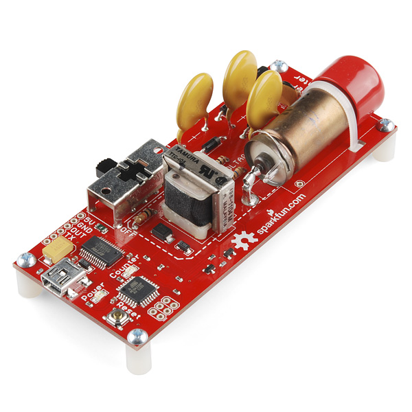
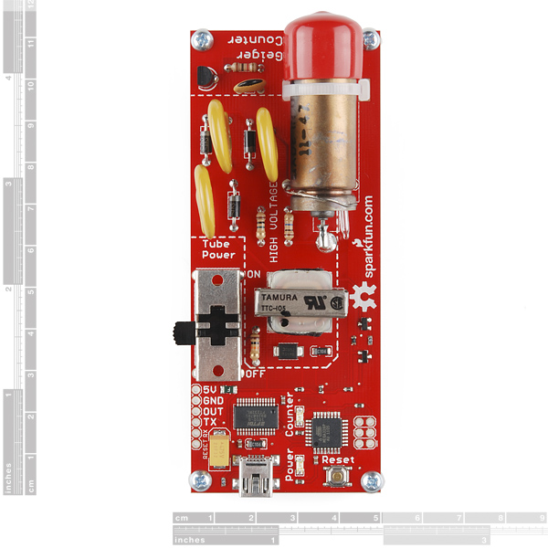
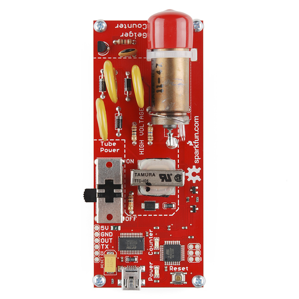
We've revised the Geiger counter once again, this time replacing the switch with a more robust right angle switch. This version also includes the necessary capacitor to support Arduino's auto-reset feature. This USB powered Geiger Counter is equipped with an ATMega328 that can be programmed in circuit using one of the programmers below. Simply plug the unit into USB (make sure you have FTDI drivers installed), open a terminal program to the correct COM port at 9600bps, and you will see random bits being generated from the random background radiation. Each bit generated (actually an ASCII byte, 0 or 1) represents an actual event in the tube in real-time, so the output can be used to deduce CPM or what ever units you need. Here at SparkFun, on average, we get about 25 counts a minute.
Check out the random number generating Geiger counter tutorial for more information.
Also, check out the live Geiger Counter feed from SparkFun headquarters.
Note: While the Geiger counter is powered and the switch is in the ON position, the board contains exposed high voltage components. In order to turn the unit off, you must flip the tube power switch to OFF while the USB cable is plugged in or while the board is still connected to your power supply. The reason being; when you move the switch into the OFF position, the high voltage lines are bled out through a resistor connected to ground, more information on this is in the tutorial.
A project box or enclosure is suggested. Do not touch the end window of the Geiger tube and do not to touch any conductive region inside the area marked HIGH VOLTAGE when the Geiger tube is powered ON. An enclosure is not absolutely necessary, but if you choose not use an enclosure, remember to be extra careful with the end window and high voltage regions.
The Geiger tube comes with a red boot to protect the end window during production, handling, and shipping. The boot should be removed if you need to detect alpha particles. However, you should still see activity from gamma and beta particles even with the boot on.
This product is controlled for export by the United States. Sending it to other countries may still be possible, but will require additional information prior to shipment.
Note: This product is for educational purposes and should not be directly relied upon for determinations regarding one's health or safety.
Features:
- 5V@30mA input
- LND712 Geiger tube
- ATMega328
- FTDI USB
- Power and status LEDs
- TTL output pin from tube
**Replaces: **SEN-09848
- 4.15"x1.75"x1" (without standoffs)
Comments
Looking for answers to technical questions?
We welcome your comments and suggestions below. However, if you are looking for solutions to technical questions please see our Technical Assistance page.
Customer Reviews
No reviews yet.
Wow, that sold out fast. Weren't there like 20-some yesterday?
yep. we've been going through these like crazy.
I sure hope the next version has a switchable piezoelectric resonator, (so it can make the classic, ultra-cool SciFi "clicks") a power switch that can properly take down both the high and low voltages correctly (DPDT switch and a bleeding resistor), a voltage regulator and a 6-9V input and an optional clear project box with provision for holding a rechargeable LiIon battery!
Or at least have the next PC board version set up to support all of those features being soldered on by the user.
Not complaining you know, just doing some fun mental engineering!
The FT232 is missing a cap on the 3.3v internal regulator pin.
From the FT232 datasheet: "+3.3V output from integrated LDO regulator. This pin should be decoupled to ground using a 100nF capacitor. "
Do you guys actually bother reading the datasheets, or have any QA? it may work without the cap, but it will likely have reliability issues. The FT232's internal regulator runs the whole usb transciever.
Ah, the infamous SparkFun Free Day Geiger Counter. Very cool
Am I the only one who wants to buy one of these, take it apart, and re assemble it in the shape of a sonic screwdriver?
Probably not.
Unfortunately, Pachube apparently requires a username and password (which I, and most other readers, do not have). When visiting , I get a dialog that says:
Cancelling this dialog results in the response:
Raw data, please?
Nice product and found out I had no difficulty in picking up K40 disintegrations which actually surprised me. The integration times are long, but putting a bottle of K-citrate capsules in front of the GM tube gave 20 counts/minute which is easily distinguishable from the 15 cpm background that exists in my Kamloops basement.
The one caution about using this unit as a source of random numbers is that it's biased. There are far too many short intervals under 100 msec and the 47 msec interval appears far more often than one would expect by chance. What I did to measure the intervals was to write a quick and dirty VB6 program which timed the occurrence of every serial byte transmitted from the Geiger counter to 1 msec precision using the windoze TimeGetTime call. Perhaps increasing the size of C9 might work, or one could "debounce" the signal in software.
That aside, the unit has exceeded my expectations and I'll likely be ordering a few more in the near future. A more detailed description of looking at K40 counts is given at: http://drgimbarzevsky.com/Electronics_Blog/blog.html
Why such an expensive tube for an "educational kit"?
At only 30mA, I assume I can power this via a digital out pin on an Arduino, since their output pins are rated at 40mA?
Eh, maybe. I wouldn't suggest it, but trying wouldn't hurt. You are getting close to the spec and the peak current draw could be slightly more than what we quote (i.e. average != peak), for example when the stat LED lights.
Hi! I need some tech support on this product! I had order one of this some time ago... After some time I get some problems with related with "low count events"(less than 10 counts per minute) I had contacted the support at that time and they said that my tube is ok! But after some time I left it off and now I turn it on and get even less counts! I had messured the H.V on the tube and discovered that the tube are getting around 1K.V (I messured directly with high impedance meter more than 100M input) Can I get a new tube? I need some assistence on this matter!
The tube contains a mixture of Neon and Helium gases at low pressure. My guess is that air is getting into your tube and blocking the radiation or throwing your counts off. Sparkfun sells replacement tubes now. https://www.sparkfun.com/products/8875
Were the previously mentioned problems with overvoltage, switching noise, interrupts missing pulses, and the capacitor on the output lengthening the pulses resolved in the last revision? I just bought one but wasn't sure if these things were fixed or if I need to hack it.
Overvoltage: The new revision will fix this and make sure the voltage is clamped at 500V. The current board might have some overvoltage on the tube, but we haven't confirmed any failures due to this.
Switching noise: If you are referring to the measurement node, the current design follows the recommended circuit given to us by the tube manufacturer and there isn't much noise from the power supply there. Taking the measurement from the other end of the tube does make things easier with cleaning the output and the polarity of the signal, but it really isn't a mandatory addition, however I have tested this and it works okay.
Interrupts missing pulses: The interrupts on the 328 will very likely not miss any pulses due to the pulse width of the signals being large enough from the output capacitor.
Output lengthing pulses: I have made a slight improvement that will give you a higher sample rate, but the current design works up to about 40 counts per second. When using any RC filter, you have to deal with the time constant of the capacitor and that will limit the sample frequency. Also, pulses can be missed if they close enough together. But this is an inexpensive (parts and labor) option to cleaning the signal, that works well enough for most applications. If you are needing more bandwidth than 40 counts per second, you should get a scientific grade instrument.
With only minor changes the current board can be adapted to accurately measure 1000 cps.
Without changing the code at all, changing C2 to 670 nF, R10 to 20K, adding a 4k resistor to the collector of Q4 (desoldering and connecting the resistor), and changing C9 to 300 nF will give a 1000 cps functionality (confirmed) with about a 1% overcount due to events that happen right before a power supply switch.
The power supply design does produce a lot of noise at the "sig" signal if the R10 and C9 values aren't huge.
This can be nearly fully corrected in software by merely ensuring the interrupt remains low for more than XX microseconds (a 100 uS pulse is generally much larger than the supply noise pulses with the smaller RC time constant and can be used to determine that the interrupt was due to an actual cascade event and not just the power supply noise).
I kinda liked this kit. It works and it's a nice tool for understanding simple boost conversion, capacitive coupling, and RC filtering. Although, would it have killed you guys to add an oscillator footprint on the board (even if you didn't include the oscillator?) ;) I soldered an 8 MHz oscillator to the 328P by hand and just reprogram the device through the Arduino IDE as a mini/micro 8mhz 5v it seems that the $1 expense to make this Arduino compatible (without messing with fuse settings) would be worth it. Also, serial communication on an internal RC oscillator is sketchy (I realize the current design just works by sending asynchronous noise over a serial connection, but modifying the device to send cpm/cps/cph is tough without an oscillator).
Awesome! Thanks for the quick reply!
It's mostly just a fun project for me, so I don't need it to be terribly accurate. Thanks for the info.
Is there a tutorial available for interfacing the geiger counter to a datalogger like the logomatic?
I built this geiger counter into a little box with a gps, arduino, and openlog.
People may be interested.
Comments are welcome.
http://wordpress.michaelgregg.com/?page_id=233
I'd like to say that working with this board was a pleasure.
Awesome your project. Where can i download gps_vars.h for your project?
Can any one tell me the frequency of the oscillator that is used for the high voltage supply?
My logger has been running for over a year now in Seattle: http://nwrs.net/radiation/
Typically, not much happens, but occasionally i get some interesting "upset events". I am not sure if it is the hardware wigging out, or if these are real. The sensor is on a table facing a corner of my house with nothing disturbing it. it is not pointing up either.
Had a burst of 1314 cpm last month with similarly high peaks for over an hour: http://nwrs.net/RadiationBurst-043012.png
also, had a similar event that only lasted about a half hour in july: http://seattlewireless.net/~casey/?p=129
Anyone have any thoughts on this?
I am trying to udgrade my firmware to V13. I got the code and created a new sketch named GeigerCounter where I've added the Main.c. The source compiles ok but I cannot complete my Upload.
I invariably get the following error: avrdude: stk500_getsync(): not in sync: resp=0x00
The latest FTDI drivers are installed, i've tried selecting all teh boards with ATMega328 but get teh same error.
I see teh green LED blink during the upload but it looks like the controller does not ack back anything.
Any ideas what can be wrong? Thank you in advance
What software are you using to program the board? I'm assuming AVRdude is being used by something else (like AVR studio or the Arduino programming environment).
One thing to note with his board is you NEED to make sure when you program the thing that your fuse settings specify the internal RC oscillator in the 328P. If you try to program this chip and you set the fuses to use an external resonator, you're in trouble.
My guess is that you accidentally programmed the thing with fuse settings that specified an external oscillator (no oscillator is connected). If this is what you did (and I suspect it's what you did, you might just want to get yourself a fine-tipped soldering iron and solder an oscillator to the chip so it has an external crystal oscillator. I really don't know why Sparkfun didn't splurge for the $1 oscillator on a $150 board. If they had, this thing could be programmed REALLY easily. It could even ship with the arduino bootloader so people could just program the thing from the serial port and not worry about the ISP programmer.
Have people been using this sensor for anything other than to showing off to their friends that they own a geiger counter? :D
Here is a very well done write up about some of the hardware bugs found in the Gegier Counter. Thanks for the feedback! We will work on some of these changes in the next revision. But for now, keep in mind the voltage on the board might degrade the life of the tube over long periods of time.
FWIW, I have been running a board for almost a year straight with no problem; background radiation counts are on par and it responds reasonably to an increase in radioactivity. However, if you are trying to measure precise counts, high emission rates, or need a counter that will last as long as any given manufacturer's warranty, we suggest using a scientific grade Geiger counter.
Could you tell me where can I download the gps_vars.h for Michael Gregg Geiger Counter project?
Thank you for the document. It looks like the new design changes are going to be good ones.
I have noticed that I am able to max out the counts per second with some sources that should be running hotter than I am measuring. This isn't a big problem as something 60 counts/second is not something that I encounter very often. I'm glad to see something about this in your write-up.
I wrote a version of the Geiger Counter firmware that uses the Arduino/Wiring libraries and the TimerOne library to create code that is more readable and easy to understand for beginners. The sketch can be found here.
Uploading it to the counter can be a bit difficult, but here is the way I recommend:
Run the following avrdude command, replacing /path/to/hex/file.hex with the location that you noted earlier, and /dev/deviceentry with whatever /dev/tty.usb* entry your programmer shows up as.
avrdude -c avrispmkii -p m328p -vvv -e -P /dev/tty.usbmodem621 \ -U flash:w:/path/to/hex/file.hex -U lock:w:0x0F:m
Hopefully that works for you. Good luck!
Are there any plans for sparkfun to offer a BlueTooth-enabled version of this?
That would be a great project, especially as it lends itself to an Android programming exercise.
There are bluetooth enabled Geiger-counters on the market (e.g. blueGeiger PG-15 and a version of the TERRA MKS 05), but it would be more fun to build one from scratch.
Just wondering I know these aren't meant for any serious measuring but about how close to being accurate are they? Has anyone taken a known calibration sample and checked to see what their ballpark is?
Actually, the older model that I've been graphing for about a year now, had a short term spike that went from my normal 24 to the 80's. It didn't occur the same time as one of the CME's hitting the earth, I suspect one of those middle of the night trains carrying special cargo's, I'm about a mile from the main line running through Eastern Washington. :)
http://www.nas-kan.org/mrtg/sparkfungeigercounter-week.png
What am I missing - no input signal on Q3 base. The schematic has the net name "osc2" but there are no other nodes on this net that I can see. The Eagle board file also shows this net as isolated. How is oscillation introduced to Q3?
It's self-oscillating. Q3 and Q1 form an astable oscillator.
Basically R2 charges C2 until the voltage at the emitter of Q3 rises above Q3's base by it's threshold voltage. At that point, the transistor begins to conduct, which turns on Q1.
Q1 turning on pulls the voltage at the R1-R2 node to ground + D1's drop. Since R3 and R4 are no longer forming a voltage divider, this pulls the base of Q3 down, turning on Q3 even more.
At this point, C2 discharges through R2 and through Q3 (into the base of Q1) until the voltage across C2 is no longer high enough to turn on Q3 (and through Q3, Q1). At this point, the collector of Q1 goes high again, and the process repeats.
It's a pretty clever oscillator, even if it is drawn in a rather confusing manner. It has the advantage that since Q1 is a high-voltage transistor, when Q1 turns off, Diode D1 is reverse biased, so effectively both windings are put in series, which allows the circuit to produce a higher voltage.
thx for your explanation. Could you also tell what the frequency is of the oscillator.
I don't know why I think this is so funny. But nearly every 'related product' was also out of stock. Guess I know how they are related.
Woo Hoo! I got an email this morning saying that ONE, count them, 1... of these was now in stock. I figured "Great, that's like throwing one Pork Chop to a pack of starving Chihuahuas..." No way will it be left by the time I log in! But lo! There were 11 of them!
This will go great with those new LiPo shields you added last friday.
is is possible to connect this board to a Mega 2560 and collet the data to an openlog ?
Sure, why not? Just connect the serial lines from the header on the Geiger Counter board to one of the serial ports on the mega. That's how I was going to connect it. (But to an Arduino Pro.)
Looks pretty cool