- Home
- Product Categories
- Sensors
- Triple Axis Accelerometer Breakout - MMA8452Q

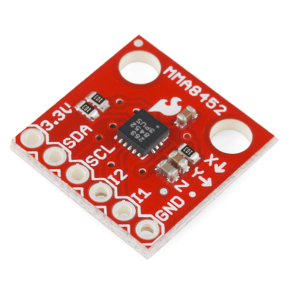
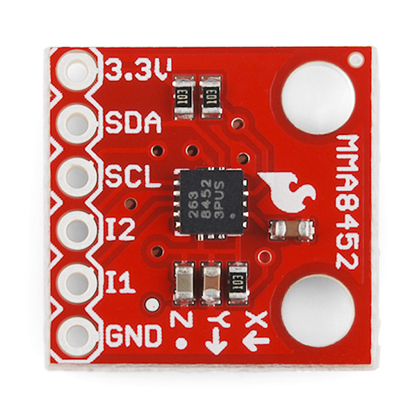
Triple Axis Accelerometer Breakout - MMA8452Q
This breakout board makes it easy to use the tiny MMA8452Q accelerometer in your project. The MMA8452Q is a smart low-power, three-axis, capacitive MEMS accelerometer with 12 bits of resolution. This accelerometer is packed with embedded functions with flexible user programmable options, configurable to two interrupt pins. Embedded interrupt functions allow for overall power savings relieving the host processor from continuously polling data.
The MMA8452Q has user selectable full scales of ±2g/±4g/±8g with high pass filtered data as well as non filtered data available real-time. The device can be configured to generate inertial wake-up interrupt signals from any combination of the configurable embedded functions allowing the MMA8452Q to monitor events and remain in a low power mode during periods of inactivity.
This board breaks out the ground, power, I2C and two external interrupt pins.
Not sure which accelerometer is right for you? Our Accelerometer and Gyro Buying Guide might help!
- 1.95 V to 3.6 V supply voltage
- 1.6 V to 3.6 V interface voltage
- ±2g/±4g/±8g dynamically selectable full-scale
- Output Data Rates (ODR) from 1.56 Hz to 800 Hz
- 12-bit and 8-bit digital output
- I2C digital output interface (operates to 2.25 MHz with 4.7 kΩ pullup)
- Two programmable interrupt pins for six interrupt sources
- Three embedded channels of motion detection
- Orientation (Portrait/Landscape) detection with set hysteresis
- High Pass Filter Data available real-time
- Current Consumption: 6 μA – 165 μA
- Schematic
- Eagle Files
- Datasheet (MMA8452Q)
- Example Code
- GitHub
Triple Axis Accelerometer Breakout - MMA8452Q Product Help and Resources
Are You Okay? Widget
May 23, 2014
Use an Electric Imp and accelerometer to create an "Are You OK" widget. A cozy piece of technology your friend or loved one can nudge to let you know they're OK from half-a-world away.
Core Skill: Soldering
This skill defines how difficult the soldering is on a particular product. It might be a couple simple solder joints, or require special reflow tools.
Skill Level: Noob - Some basic soldering is required, but it is limited to a just a few pins, basic through-hole soldering, and couple (if any) polarized components. A basic soldering iron is all you should need.
See all skill levels
Core Skill: Programming
If a board needs code or communicates somehow, you're going to need to know how to program or interface with it. The programming skill is all about communication and code.
Skill Level: Competent - The toolchain for programming is a bit more complex and will examples may not be explicitly provided for you. You will be required to have a fundamental knowledge of programming and be required to provide your own code. You may need to modify existing libraries or code to work with your specific hardware. Sensor and hardware interfaces will be SPI or I2C.
See all skill levels
Core Skill: Electrical Prototyping
If it requires power, you need to know how much, what all the pins do, and how to hook it up. You may need to reference datasheets, schematics, and know the ins and outs of electronics.
Skill Level: Rookie - You may be required to know a bit more about the component, such as orientation, or how to hook it up, in addition to power requirements. You will need to understand polarized components.
See all skill levels
Comments
Looking for answers to technical questions?
We welcome your comments and suggestions below. However, if you are looking for solutions to technical questions please see our Technical Assistance page.
Customer Reviews
No reviews yet.
Great board but it has some I2C compatibility issues. I downloaded the example code but was surprised to see it did not use the standard Wire library. I was able to rewrite the code to use Wire but learned about an issue this board has with the Wire.endTransmission() function. Unlike other devices, the MMA8452 (and some other I2C devices as well) need a flag to keep the I2C connection alive during a read sequence. The issue is described here: http://arduino.cc/en/Reference/WireEndTransmission When I used Wire.endTransmission(false), it fixed the problems I was having with the standard wire library.
However, there is still one major limitation if you plan to use this device with an ATTiny device (as I had). The TinyWireM library does not implement the false flag in its TinyWireM.endTransmission() so, until that feature is added, you can't use this board with ATTiny devices - a serious bummer. If anyone has a workaround - please let me know.
HELP ME !!! The example code is fails c (0x0D) no return 0x2A. I doing wrong?
I get something similar running the AdvancedExample from sparkfun. This is what I get Could not connect to MMA8452Q: 0x3B
I could have sworn I had this board working a year ago.
What are the pros or cons of this device relative to other digital-interface 3-axis accelerometer chips that are available?
I chose this device because
1) Price. I did not need the functions of the $30 accelerometers, so $10 is nice. 2) The 12-bit adc is better than arduino's. I'm trying to resolve single axis degree from 0-90 degrees tilt. A higher resolution adc makes it easier 3)2g range setting. I'm basically going from -1 to 1g, so I gain 23% more resolution over a 3g range item (maybe more than 20%? Am I thinking right? Utilizing 1/3 range in one condition, 1/2 range in the other condition).
Minor things: The device doesn't draw much power, but I like the from wake-up from standby. Cons: Figure out how to use I2C Figure out how to talk to this 3.3v sensor with my 5v board (D'oh! At first i thought I'd just use aref 3.3v and 3.3v rail, but then I realized after I purchased that the data connection probably won't read properly on a 5v digital pin. Still investigating at the moment).
That said, this is not really a "pros and cons" list. Rather, it's me iterating a few of the reasons why I chose this acellerometer. In reality most applications really care about drift, as well. My application does not. So you want to be thinking "Do I want digital or analog? Does this have sufficient resolution & range? Is the drift level ok for your usage? Do I want any of the digital functions of the next more expensive sensor (if applicable)?"
I'm not sure if this is the best advice, but I'm throwing my two cents out since no one else has.
I haven't figured out the I2C yet either but I just started messing with that.
I have a 5V board as well. Pick up a voltage regulator(Sparkfun sells em). You can talk to it on the 5v lines with the example code given.
I have no clue why I2C has so many libraries for arduino but I guess they are all needed. It is kind of annoying but probably necessary.
There's one official I2C library, the "wire" library, which is included with Arduino. This handles communications to any I2C device in a standardized way.
The other libraries you're referring to are probably the libraries for individual devices; these are necessary because each I2C device does something different, and thus needs different commands sent to it, results coming back, etc. The wire library handles getting the bytes back and forth, the other library will know what the bytes mean.
It may seem overwhelming if you've never used I2C before, but you'll find that Arduino makes it quite straightforward. And for any particular device, you'll only need the base wire library, and the library for that part.
Check out the guy at the bottom of this thread, he links a working library for the I2C and general operation of this device. It needs a particular start signal. ^_^
The post is 2 months old
If i supply this board with 5v and a voltage divider (R1 330ohm R2 660ohm giving 3.333v) would it work? and would the extra 0.033v be to high for it?
I never recommend powering things with a voltage divider. The resistors limit the current too much, meaning you'll have the right voltage, but not enough current to do anything. In this case it might work but no guarentees. As for voltage you should be ok, check the datasheet but they should be fine up to 3.6V
hi, i want to ask a question, for this accelerometer, 2g--1024 counts/g 4g--512 counts/g 8g--256 counts/g how can i convert counts/g unit to mV/g or V/g?, could yo help me? thank you
I can't get the basic sample to run on Teensy 2.0 Any idea on what's going on?
It chokes on the first call to the wire lib.
I was able to modify the RedBot accelerometer (MMA8462Q) CPP file to add two's complement checking and LSB shifting ala the advanced example in the Example Code above. Everything works as expected EXCEPT the g values are four times too large. I checked and double checked that the scale setting is +/- 8 g, I'm in the low res mode, the logic looks fine, and I'm dividing the count by 256 for the 8 g scale and I am getting ~+4.00 g in the z-direction, not ~+1.00 g as I expect. I'm using 8 for the scale factor in constructing the divisor for the counts (1/(1<<12)/(2*SCALE)) = 1/256 for 8 g full scale, yet I am getting an extra factor of four. I checked the raw output of the concatenated z-bytes which was ~16000 unshifted = 14-bits! What gives???
Any suggestions for what could be going wrong? Thanks.
same problem
I think this is due to the fact that the sensor is factory calibrated at 2g for Zero-g offset. If you plan to use it with a different scale you should recalibrate offsets to get 1g at z when stationary.
The value at the offset register is stored using the scale at calibration time, if at 2g then 0.25 mg/count, so if you change scale to 4g without recalibrating then at stationary will read double value (2g instead of 1g) beacuse at 4g it is 0.5 mg/count, so same number of counts in the offset register will read double g.
here some explanations: http://purposefulscience.blogspot.com.es/2014/04/balancing-multirotor-motors-with.html
I am working on my first Arduino project, and looking to interface with an Accelerometer to attach to the back of a washing machine. I want to monitor, and determine if its moving (i.e. ON). Do you think this is sensitive enough? Anyone got an suggestions? (It's not for homework, its a part of random idea process for a handicapped person in my neighborhood) Thanks.
I want to confirm what some other comments have said. I am using my MSP430G2553 launchpad, Energia and the Basic Example from Sparkfun at 3.3V.
The 10K pull ups are too large. I connected the SCL and SDA lines to an oscilloscope and they are rounded off horribly. It explains why my plotted data from the chip is incredibly "noisy."
4.7kΩ pull ups work great though. The SCL and SDA aren't exactly square, but are less rounded and the plotted data is clean.
Sparkfun, as other have suggested from years ago, please sell off the stock you have and revise these boards to R1=R2=10kΩ.
I am using an Arduino Mega. When i upload the basic code it reads out "MMA8452 Basic Example" then nothing else.
How can I use this item with the BOB-00099 RTC module? I am using Arduino mega/uno.
I noticed that you guys sell the MMA8452Q separately and also that the I2C addresses (you can choose between two by default) can be designated at the factory. I need to have up to 8 of these functioning on the same microcontroller, is there any chance you guys can request address reconfiguration on a few units so that I can order them through you? I love this little breakout board.
My guess would be no, simply because we'd have to do a custom order, and then a custom build on this (there's a lot of steps that would possibly lead to the ICs getting mixed up along the way). You may want to verify with customerservice@, but I wouldn't recommend getting your hopes up.
I have a similar requirement where I need multiple 3 axis accelerators on the same i2c bus. Is there a recommendation on how one might go about this? Is there another product that might have programmable addresses?
The easiest option would be to use something like the Analog/Digital MUX Breakout board. This would allow you to use several accelerometers with the same address on the same bus. You would need one board for the SDA lines, and one for the SCL lines.
So I've been using these, and normally they work fine, but recently, they have started shorting on me. They'll be working fine, then all of a sudden, I'll resupply power and nothing will work. If I remove the the MMA8452, everything else works. Then when I test the pins on the actual breakout using a multimeter (with it removed from the breadboard I am using), there is continuity between VCC and GND. I am running everything off of a 9v battery plugged into the RAW pin of an 3.3v Arduino Pro Mini, which properly regulates down to 3.3v as expected (verified with multimeter). I can swap in a different MMA8452 and everything works again. I have soldered standard straight pin headers to all of the breakouts, but I can't imagine that that is the issue, since it only happens after using the accelerometer for a little while, so I don't think it is a solder bridging issue, but I suppose it could be.
Any ideas as to what might be happening? Is there anything that might cause a working PCB to short, or did I just get unlucky with the manufacturing? I would like to be able to fix anything that I can, since I've already killed 2 and only have 1 left to work with, and I would rather not buy more if the issue is going to keep happening.
If anyone gets this working on a Due on either set of ports, please let me know.
Thanks.
The example code (https://github.com/sparkfun/MMA8452_Accelerometer/tree/master/Firmware/MMA8452Q_BasicExample) doesn't work with an Arduino Leonardo. The Leonardo runs okay for 15 to 30 seconds, then hangs.
hello,
i am attempting to cross-compile this example MMA8452Q aduino code for the raspberry pi:-
https://github.com/sparkfun/MMA8452_Accelerometer/tree/master/Firmware/MMA8452Q_BasicExample
i am getting all sorts of missing library and header errors (all of which i located in the "arduino-1.0.4" folder i downloaded). trouble is, every time i satisfy one library, i get a new error the next time.
1) is it possibly to compile this code without the arduino compile environment (ie just a standalone linux gcc compile) ?? 2) if so, how do i satisfy the library requirements, since the needed files are scattered all over the "arduino-1.0.4" folder ?? 3) does anyone have a simple makefile or shell that i can use to satisfy the dependencies? (better yet, anyone done this for the raspberry pi???)
sorry if this is a silly endevour-i want the code but i dont want all the arduino fluff that goes with it.
thanks!
andrew.
Hello everyone! I have read the datasheet and the AN4076. On page 5 of the AN4076 it sais that with an ODR of 800Hz every sample the time detween every sample will be 1.25ms.So if i am interested in reading only one axis its value will be refreshed every 3.75ms? can't this get faster?(for example turn off the sampling on the othr two axes?) Another confusing point is at the AN4075 where it is stated on page 6 that the internal sampling rate is 1600Hz.The max 800Hz ODR is computed with the oversampling of two samples on the internal sampling frequency?
It samples all three axes simultaneously at up to 800 Hz ODR, which is 2x oversampled internally.
I have bought this accelerometer and I am using it with arduino uno. I have used the sample code from this just to display the x y z axis.But i am getting an error in the serial port. It basically is not able to pick up the value stored in WHO_AM_I register. Can anyone please help me.
Thanks for the sample code. Would have taken me a few days to put together but I was up and running in under 5 mins!
I have the pull up resistors wired up like the schematic, and then everything hooked into the arduino from the instruction in the advanced example. I am getting could not connect to mma8452q:0x1a. Any ideas?
Hello SparkFun friends. My kids and I are new to Arduino and, in connection with work I'm doing with Sandy Hook Promise, starting to experiment with how we'd build a tampering detector for firearms.
First step, we've acquired a SparkFun Arduino kit and one of these 10955 / MMA8542Q accelerometer breakout boards. And, we quickly got stuck. Here's what we've done:
Here's how we connected things:
10955 / Arduino
3.3V => 3.3V
Gnd => Gnd
SDA => A4
SCL => A5
ID1 => 1
ID2 => 2
I haven’t added any circuitry to pull up the 3.3V logic signals to 5V — it sounded from the discussion like that shouldn't be necessary. (Am I missing something?)
We're using the code and libraries linked below, and it's hanging so long as the SCL pin is connected.
Here's the relevant code:
#include <I2C.h>
#include <MMA8453_n0m1.h>
MMA8453_n0m1 accel;
void setup()
{
Serial.begin(9600);
accel.setI2CAddr(0x1d);
I2c.begin();
accel.dataMode(true, 2);
}
In particular, the call to accel.dataMode(true, 2) doesn't return if SCL is connected. Removing SCL connection, it proceeds into loop() but there's (obviously) no meaningful data coming through.
Stuff I’ve tried that doesn’t change behavior: – adding I2c.begin() – disconnecting I1/I2 – either address 0x1c to 0x1d
Seems strange to me that the behavior is the same regardless of address.
Thanks for advice!
I'm having this same problem, did you ever get it figured out?
I bought this to use with a Raspberry Pi and unfortunately determined these two devices are incompatible. The incompatibility is a result of the RPi not sending repeated starts correctly. Basically, the RPi can write to any register but can only read the first 7 registers on this device.
Anyone having trouble setting the dynamic range to 8G? I have comms working, and can verify the device ID and read data. However, my data is always coming in with a 2G dynamic range, even when I set XYZ_DATA_CFG to FS1.
I bought this to make the classic “Oh Fudge!” Prank.
I didn’t want to spend $28 on a ADXL345 Accelerometer, when the MMA8452Q is a much cheaper. The only down side to the MMA8452Q, is the lack of a Arduino Library for it.
So, I decided to offer the Arduino Code I used to make the “Oh Fudge!” using a MMA8452Q.
Here it is: http://pastebin.com/JKPSFxAe
I hope that helps all you “Oh Fudge!” Makers!
I would like to suggest that if you are going to keep putting pull-up resistors on breakout boards (as if they were the ONLY thing on the I2C bus), that you also provide jumpers so that they can be easily removed without having to desolder 0402 smt resistors. Thanks.
Thanks for the feedback, we have started doing this on some of our boards. I'll add that if you want them gone, 402s are pretty easy to knock off with a soldering iron.
Can you Offer Variations of this with different I2C Addresses? It would be great to be able to read several of these at once. I see there are provisions for handling two variations, but I'd like a couple more.
It would be simple if you would mark them 1A,1C,1E and give a different versions. then the with the SDA line make them shift to 1B, 1D, 1F.
That would make it easy enough to chain 6 together for more complicated solutions using single I2C lines.
Thank you, -Sean Reynolds
Has anybody been using this with Netduino? I can only partly access the registers. Following are some parts of the code I wrote:
// Freescale MMA8452Q I2CDevice.Configuration Conf = new I2CDevice.Configuration(0x1D, 50); I2CDevice icD = new I2CDevice(Conf);
// Set it Active (This part works correctly) I2CDevice.I2CTransaction[] writeTransaction = new I2CDevice.I2CTransaction[] { I2CDevice.CreateWriteTransaction(new byte[] {0x2A, 0x01}) }; int bytesWritten = icD.Execute(writeTransaction, 50);
// Try to read Device ID (This part does not work correctly) I2CDevice.I2CTransaction[] rwtransaction = new I2CDevice.I2CTransaction[2] { I2CDevice.CreateWriteTransaction(new byte[1] { 0x0D }), I2CDevice.CreateReadTransaction(data)
It seems that the read register is not set to 0x0D, but that it is set to 0X00, hence the byte array "data" contains the content of the registers starting at 0X00.
Has anybody made the same experiences and found a way how to address this?
Thanks - Thomas
Are there any non-arduino code examples for how to use this?
Try a quick google search of MMA8452Q + whatever board you are looking to interface this with. You should be able to find some examples that way. Otherwise, I'd look up an example I2C interface for your particular board and work with that and the sensor datasheet to get up and running.
I have two questions:
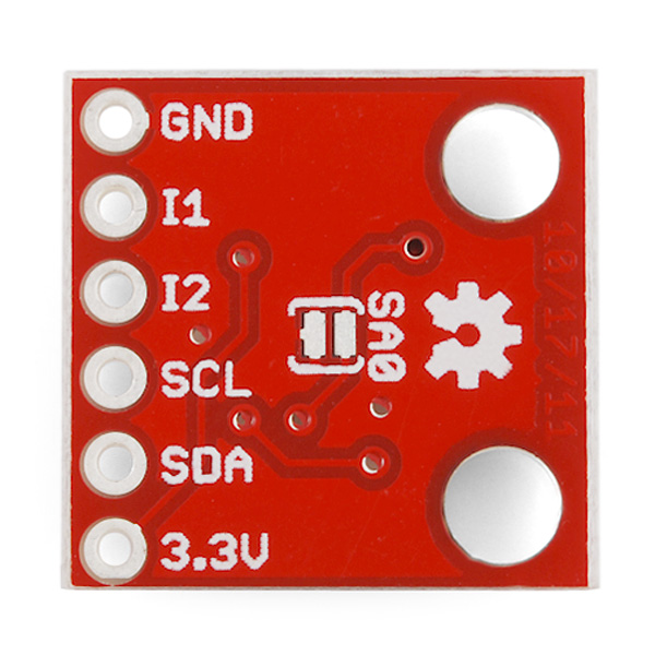
1) How/where do I complete the jumper to the SA0 pin. I plan on using four of these, in 2 groups.
2) What can I do to monitor two separate accelerometers with the same address. I need a way to combine them so I can tell when one is accelerating. Doesn't matter whether one is moving or both, just need to identify motion.
Thanks in advance.
I adapted the I2C library used in the example code to work with the new Arduino Leonardo which uses an ATMEGA32U4 instead of an ATMEGA328.
I've uploaded the changed i2c.h file to a bitbucket repository in case anyone else is interested in that: https://bitbucket.org/wizard23/arduinoleonardolibraries/src/39d52819baae/i2c.h
If you just replace the i2c.h from the above Example Code then it should work on the arduino Leonardo (or any other ATMEGA32U4 board)
The only thing I had to change was the definitions of WRITE_sda and READ_sda because that pin is on a different port on the ATMEGA32U4.
I used the sensor in my own design (thanks sparkfun for the eagle library (although I had to adapt it because the NC pins are not connected to the package and according to Freescale Application Note AN4077 you should connect dummy traces to the NC pins...)) and now I can already read the sensor values :)...thanks again to sparkfun for this awesome code example!
Will it be safe to run this straight off of a li-ion?
When I apply input voltage 3.3V to the power pin all the pins go high 3.3V with exception of ground including the Int pins. From what I read in the spec this doesn't seem right at all? They don't change no matter what I do connected or unconnected..The device reads back 0xff...Has anyone measured the voltage on the pins immediately after applying power? I wonder if I got a bad board?
I got this to work with Arduino v23 using the provided software, but can not get it to compile using Arduino V 1.0.1. Cleaned up most of the error messages (going from 23 to 1.0.1) Still no luck. Has anyone used this board and provided software with Arduino v1.0.1??
I found working library for this module: MMA8452 Library and Examples All is working fine.
Many many thanks! That helps me quite a bit.
I was connected this module to arduino uno via logical level converter but example code doest work, "could not connect to MMA8452Q: 3B" Can you help me ?
If I'm powering one of these off of the 3.3 volt pin on an arduino that is talking to other 5 volt devices, do I need a logic level converter like http://www.sparkfun.com/products/8745 to insure the signals are 3.3?
The comments in the example code seems to imply the code takes care of the issue so I would not, but I don't see how it does that.
After researching on the forums and a helpful email from sparkfun, I have concluded (and confirmed via experimentation) that you do NOT need a logic level converter. It will work just fine provided you power it via the 3.3v pin on the arduino. The key to understanding why this works is knowing that I2C uses "open drain" to send signals. That is, the valid states the I2C pins are set to will be ground for "low" and floating for "high". The pull up resistors on this board set the voltage to 3.3 whenever the pin is in the floating state. Properly set up, the arduino should never set those pins to 5 volts. As noted in the sample code, it's important in this case to disable the internal pullup resistors that set the floating state of these pins to 5 volts. You can't do that with the built in wire library, so you have to use a different one. The interrupt pins work because the arduino should only be reading from them, and 3.3 volts are enough to register as "high". So wiring these devices to an arduino directly works just fine, as long as you are very careful to NEVER let any of the pins they are connected to be set to 5 volts. Make sure you upload a sketch to set the pins BEFORE you wire them in, in case you have something already loaded on the arduino that sets one of the pins to 5 volts. If you set one of the pins as digital output, you could damage this device.
All great points! I'll add one clarification. The existing wire library does enable the Arduino's weak pullup resistors by default, which as you say isn't ideal for 3.3V I2C devices since these are connected to 5V on most Arduinos. (There is some grumbling about this on the Arduino forums, and I expect this problem to be fixed at some point in the future).
However, because this board has its own pullup resistors in addition to the internal weak pullup resistors on the Arduino, the smaller external resistors will overpower the internal ones to some extent. For this board, the combination of a 25K internal pullup to 5V, and a 10K external pullup to 3.3V, results in a top voltage of 3.79V on the line.
Now, 3.8V is still somewhat higher than the 3.3V part would like to see, but from the trenches, we've used 3.3V I2C parts on 5V Arduinos using the standard library for quite a while without problems. The main thing to keep in mind when connecting one of these to a 5V Arduino, is that you must supply the I2C part with 3.3V, and must have external pullup resistors to 3.3V.
So All of this talk has me confused. I see on the schematic 10k pullups but the sample code mentions adding even more resistors??. Do I require any additional resistors not on the breakout to get this working safely with the example code at 3.3V I2C?
If there are external pullup resistors present (usually either 10K or 4.7K), and you're careful to power the board with 3.3V, then no, you do not need additional resistors.
It arrived a few days ago managed to get it working within about 30 mins. Just some jumper wires and I was good to go. Thanks. Now to play with maths and wave it around.
I have this thing hooked up to an adruino nano 2.3. I am not receiving any error notes in the serial monitor but all I'm getting are 1s and 0s when it is moved. I see in the code it is set to show that when the orientation changes but I can't get it so show any x, y, or x values. I see the 1s and 0s when my serial monitor baud rate is 9600. When I change it to 115200 like I see in the code noting shows up. Help?
Hey guys,
I've triple checked my connections between this board and the UNO:
V3.3->3.3 GND -> GND A5 -> SCL A4 -> SDA 2 -> i1 3 -> i2
The example program fails because the WHO_AM_I register (0x0D) is returning 0x39, not 0x2A. Any idea what I could be doing wrong?
Yes. I was in '0x39 problem' too Default '#define SA0 0' setting in program is wrong. It should be 1 not 0. And the schematic is wrong too. It tells 'SA = 0' is default but it's not true.
Hey Sparkfun guys please correct it.
Sorry about that. Schematic is fixed and the code now defaults SA0 to 1.
Nevermind, I neglected to see that I needed to change #define SA to 1
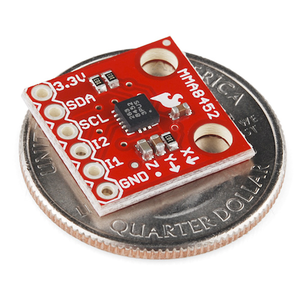
What are the dimensions of the board? .7x.7 ? It would be nice if that was part of the specs or features or something. I don't want to have to load the eagle files to figure it out.
Also, AdrianFreed has a good point and you should update the board to follow MFG guidelines.
I am putting this on my current design because our tech can't solder LCC's by hand.
Hi, Please rev. this to follow the manufacturers recommendations (i.e. 4.7k pullups, non central placement, no holes near package, traces off all pads) from AN4077.
Can you make one with the higher res. MMA8451Q too? It would be good to have the 5v regulator on there too like the competitive board from LongQi
The higher res. version is the MMA8453Q
No, that is the 10bit one. the 14-bit one is the MMA8451Q
*MMA8450Q:Xtrinsic Low-power, 3-axis Xtrinsic
*MMA8451Q:Xtrinsic 3-Axis, 14-bit
*MMA8452Q:Xtrinsic 3-Axis, 12-bit
*MMA8453Q:Xtrinsic 3-Axis, 10-bit Digital
The datasheets are remarkably similar and the core ADC is 14-bit so there must be some quality sorting going on?
Incidentally Matt your board also doesn't follow the manufacturers guidelines w.r.t. nearby holes and centrality of the package.
MattTheGeek designed a similar board.
I have sooo been waiting for this: a cheap, 3 axis accelerometer on a breakout board. Yay!
You guys have so many neat accelerometers that I imagine some people have a hard time choosing. Can you do some kind of comparison table? That would be awesome! Thanks,
There is this buying guide, though I'm not sure how up-to-date it is (and it obviously doesn't have the MMA8452Q on it yet).
Oh, cool, thanks!