- Home
- Product Categories
- Slide Potentiometers
- Slide Pot - Motorized (10k Linear Taper)

Slide Pot - Motorized (10k Linear Taper)
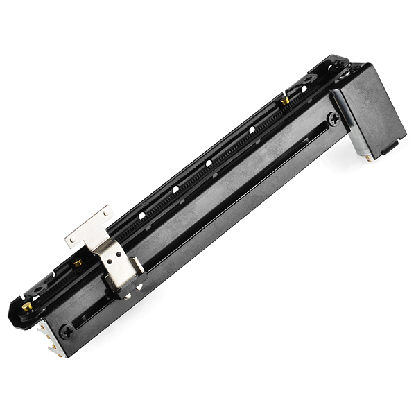
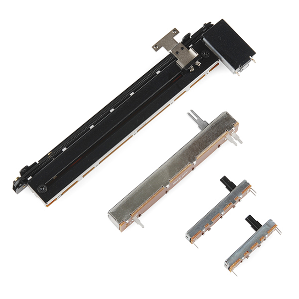
These motorized sliders are very cool. Each is essentially a standard slide pot which is belt-driven by a small motor. The slide contains two separate 10k linear taper potentiometers so that you can use one as servo-feedback in order to read the position of the slider and use the other to control whatever your target is. There is also a touch sense line which is electrically connected directly to the metal slider tab so that you can interface the slider with capacitive touch circuitry.
Motorized potentiometers are useful when you need the ability to jump to preset positions or when you want physical feedback from virtual controllers. There are also a variety of unconventional uses for these potentiometers such as pulsing the motor to provide haptic feedback or just using it as a linear actuator for super light-duty robotics.
Slide Pot - Motorized (10k Linear Taper) Product Help and Resources
Mount Screws?
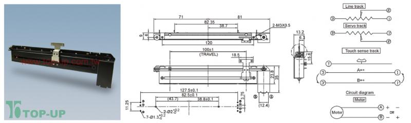
The two mounting holes that are bent to accept screws from the side look like it needs M3 screws => "2- M3x0.5" [ http://cdn.sparkfun.com/datasheets/Components/General/MD100AM2BF-D_L_MD100AM2B-D.jpg ].
1 of 1 found this helpful:
Motor Driver
In the demo video [ https://www.youtube.com/watch?v=E2Stni6W7Vc ] used a motor driver [ like the recommended motor driver TB6612FNG – https://www.sparkfun.com/products/9457 ] and Arduino microcontroller to move the motorized slide potentiometer. Unfortunately, they did not provide the demo code from the video. There should at least be an example code on using a motor driver with the TB6612FNG’s product page.
Try looking at this comment though => https://www.sparkfun.com/products/10976#comment-53d36766ce395ff8478b4568 . A customer was able to get it working similar to the demo. The code does not seem to be exactly like the demo code but it is a start.
Core Skill: Soldering
This skill defines how difficult the soldering is on a particular product. It might be a couple simple solder joints, or require special reflow tools.
Skill Level: Noob - Some basic soldering is required, but it is limited to a just a few pins, basic through-hole soldering, and couple (if any) polarized components. A basic soldering iron is all you should need.
See all skill levels
Comments
Looking for answers to technical questions?
We welcome your comments and suggestions below. However, if you are looking for solutions to technical questions please see our Technical Assistance page.
Customer Reviews
3.7 out of 5
Based on 3 ratings:
1 of 1 found this helpful:
Good quality unit, but...
You would think they would stock the slider knobs for these things. I had to print my own on a 3D printer.
Hi, You make a good point. I have passed your suggestion along to our parts hunting team for consideration. Thank you
1 of 1 found this helpful:
works ok
The rubber band was too loose and not reliable
2/5
It works! But it's definitely not evenly linear and it was a pain to figure that out. I only realized I wasn't doing something wrong when I tried a Bourns motorized slider pot and saw what a truly linear response looked like.
Great if you just need to move a slider back and forth, not great if you need accuracy.
Any chance we'll see these as a qwiic unit? With a programmable interface that will command the the slider to a set value, then leave it easy to manipulate? (Because using an h-bridge and worrying about direction, steps, jogging, stalling the motor, etc)
Hmm, these look almost exactly like Midas Pro faders used in their M32 digital mixer. You can get a set of 5 of those for $150, and they're probably much higher quality (rated at 1 million cycles instead of 30,000). Not to mention they come with cool conductive knobs and the Midas logo... these still look pretty good for the price.
I made a video about how to use this product because there seems to be a lot of confusion. https://www.youtube.com/watch?v=fEuUHqmlPD4
Can anybody please help me?
I was looking for motor-driven faders in order to implement a project. Everywhere I came across motorfaders with resistor values of 5k or 10k. Does anybody know where I can get such faders that have other resistor values, such as 20k, 100k and 500k? I would appreciate it if anybody can help me and knows where to get this stuff out there..
So it can do capacitive touch sensing? Heh heh. You guys missed a chance for a good sketch with Dave. A control that senses when someone is about to change it and dodges away from their finger.
Just created a cool audio mixing console project using this fader called the "Uni Mixer". Documentation was difficult to find. Here's a good, readable diagram I created with all of the pins, what they are used for, touch sense, etc:
https://raw.githubusercontent.com/beausilver/uni_mixer/master/Docs/DIY_Diagram.jpg
Here's a video of my project: http://youtu.be/j2H5q4l1yM4
And here's my code: https://github.com/beausilver/uni_mixer
Thanks Sparkfun, this is great fader! Cheers!
This is fantastic! Which parts did you use? any specifics please? [like: motor driver, arduino motor shield, etc.]? ...Again, KUDOS ON A GREAT PROJECT!!
After an evening of tinkering I was able to make it work akin to the example video. I don't have it set up as a pong game, but I do have it hitting programmable set points.
Hooked up with ATtiny85 (adafruit trinket) and L293D (equivalent: https://www.sparkfun.com/products/315).
I didn't have success using PWM; anything short of 255 would lock and buzz, so I changed my program around to use digitalWrite instead. Not sure if that issue was in my programming, wiring, or something else.
Here was my code. Please let me know if you have suggestions.
How much weight would this push vertically? And what part(s) would you nee to make a toggle switch move it up, and then the toggle switch pressed the other way to move it down? Would I need a circuit board or just the slide and a polarity switch
Can you publish the circuit and code for the sliders demo? Mine are moving but not very smoothly. Also, can you explain the reasoning for the dual variable resistors? Do you feed the motor power into one???
Yes this would be the best, I am trying to make an XY plotter, which would be a lot like what you have, but using a PID controller, and things are weird. Not as nice and smooth as you have.
No, you don't feed the motor power into one. They have 2 so that you can have one as a feedback loop to determine the motor position. The other one can be used for whatever you need it for. And it does not matter which one you use.
Got this working:
Photo of wiring: https://www.flickr.com/photos/lateplate/15068862612/ Arduino code: https://gist.github.com/chrisallick/49e80ea6c82eb1d9ae9d
I can post more details if anyone wants :)
Any additional discount for extra large orders (e.g. 500+)?
For anything over 250 please email sales@sparkfun.com.
no sorry this could be linear. Be carefull that another product (COM-10734) is not linear.
I have bougth it but it is not linear it is a Log fader!!!!
Any possibility of getting the 60mm version? I would order a whole bunch of them (100+). And no, I'm not kidding.
Hi Expert, I am a 15 yr-old high school student and would like to use this as a linear servo to turn 12 eggs. I bought two from your place, but I am not sure how to connect them. If you could give me some starter code/example code for me to start with, that would be great. Right now, I am using an Arduino to drive a servo to push the eggs, but I would like to use a taper. Thanks! Trevor
Annoyingly, it seems that the knobs listed as the recommended knob for this fader are not conductive at all - when trying to do touch sensing through them, there's not nearly enough sensitivity through the knob.
Found this: http://www.hazelwoodsound.com/motorized-faders-and-the-arduino/
You can find more results by searching for "motorized fader," as it seems the most popular application of this component is with audio mixers.
+1 for example wiring and code.
I just purchased 2 of these for a project, but don't know what the pins are and unfortunately don't understand the diminutional drawing. Can someone list or diagram them?
You've made a terrific project in your product video. Why not document and post that with wiring and code? I think it'd relieve a lot of frustration and eliminate many of the questions.
I'd buy this if there was any indication of how to connect it. Even just pin descriptions would be useful. The data sheet doesn't really provide much data!
Apparently the information you'd want would be in the dimensional drawing. Here's one in PDF format so you can zoom in: http://www.top-up.com.tw/ezfiles/top-up/download/attach/5/MR100RF2B-D-9-2M8.2-%20%20%20%20%20%20%20-6H.pdf
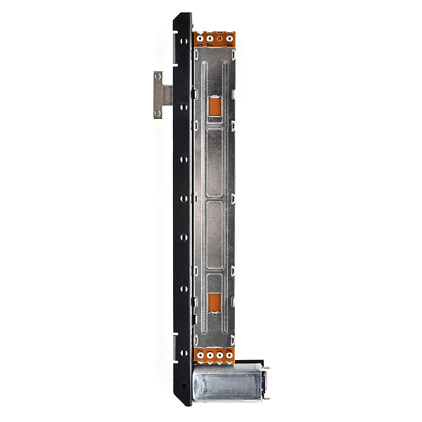
The photo of the bottom (brownish board shown) may help relate things a bit as well as those drawings aren't the clearest and the other photos are disorientating.
Is there a smaller version of this? One that would fit in a standard Single Gang wall box?
I'm surprised that there is no tutorial or schematic for how to hook it up
How fast do you think I could actuate this repeatedly back and forth at a constant rate? (Doesn't have to be full length)
I've been a happy customer of sparkfun for years, but this thing really annoyed me. There is no details in the datasheet as to how to connect this thing. So i had to try every combination. POFF... smoke. Awesome. Now I have a non working slider !!!!
I'm sorry to hear that happened. Not trying to be rude here, but why did you run a live current through the terminals without knowing what they are? There are no wires or connectors from the motor terminals to the rest of the device, so it's pretty obvious it's just a simple DC motor. You just use an H-bridge to set which of the two motor terminals is GND, and which is Vss (ie: +6V in my case).
Also, if you have a simple/cheap digital multi-meter, it is very easy to determine all 6 terminals of the two pots. If the resistance is infinite/open-circuit, it means the two terminals are not part of the same trim-pot. If the resistance is 10k-ohms, as noted in the electrical parameter datasheet provided, you know you've found the extreme connections (ie: terminals 1 and 3) for a single trimpot. If the resistance is on [0,10] k-ohms, and changes as you slide the trimmer, you know you've found the centre-tap.
Also, all may not be lost. It's possible you've only fried one of the two trimpots, not both :)
If you still have a single working trimmer, just keep this in mind: 1) You need an H-bridge to control the motor, and have it move back AND forth. The L293D (digikey part: 497-2936-5-ND) is perfect for this, and it has all the clamping diodes built into the chip, so you don't have to wire 8 external diodes. Well worth the two bucks per chip.
2) If you want to play with the speed of the motor, the easiest way would be to use a pulse width modulated (PWM) signal from your processor (eg: Arduino) to the signal being sent to the H-bridge. I use this for basic motor speed control, and it also works when using a multi-color LED to control the ratio of power for each of the red/green/blue LED components.
3) You'll need an analog-to-digital converter (ADC) to read one of the two trimpots (the center tap). I wired the extreme taps to 0V (GND) and to Vss (+6V). Since it's a 10k-ohm trimmer, not much current will flow, so this won't fry the trimmer.
I replicated their pong experiment, and the device worked like a charm with the help of some MakerBeam bearings and beams.
Hey guys! I just ordered one of these for a 9S12 project I'm working on. Does anyone have some examples of a good way to implement servo feedback? I want to use them for analog input, but recall stored positions on command like a digital sound board. The 9S12 I'll be using has 12-bit ADCs so I want to come up with a fairly precise recall algorithm, but still run it all through a single micro. If all goes well, I intend to use 12 of them side by side. Thanks!
I get an idea from the video, but are these sliders virtually silent? I have a special application where I require a linear actuator type of movement with as little sound produced as possible. Thanks!
I get an idea from the video, but are these sliders virtually silent? I have a special application where I require a linear actuator type of movement with as little sound produced as possible. Thanks!
are you acually about to sell linear actuators that can do heavier loads?
Nothing is currently in the pipe, though we already carry a stepper motor with a threaded shaft: ROB-10848