- Home
- Product Categories
- Kits
- SparkFun LogicBlocks Kit

SparkFun LogicBlocks Kit
Digital logic is the foundation of every task that a computer can do, so it's no wonder that in order to fully understand how computers and other digital electronics work, you need to be familiar with logic gates. The problem is that logic gates aren't the most "hands on" subject, until now.
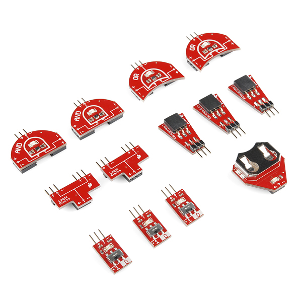
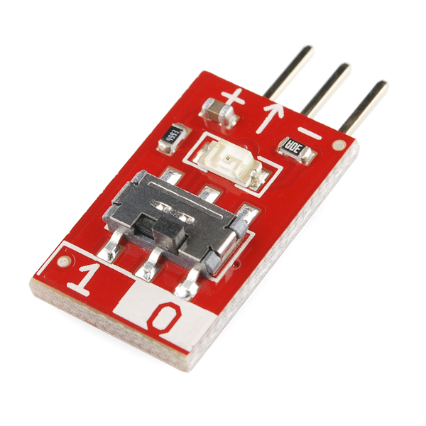
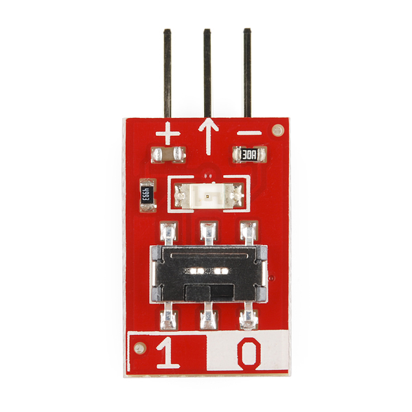
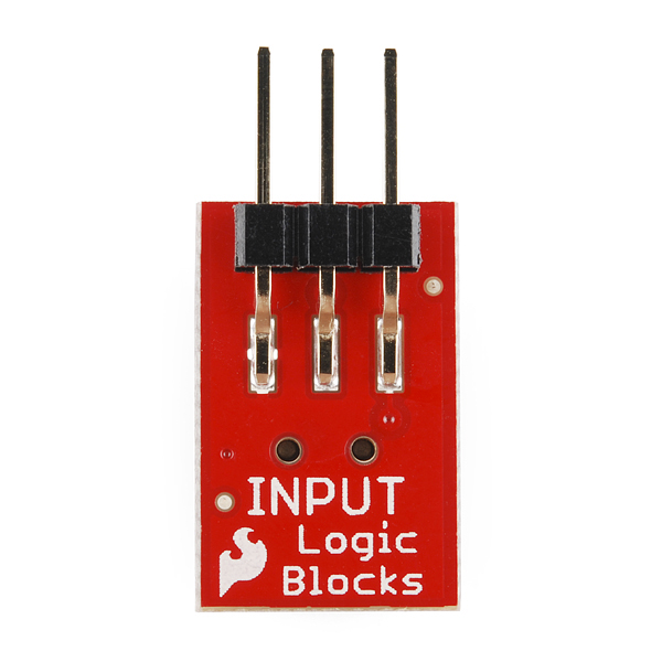
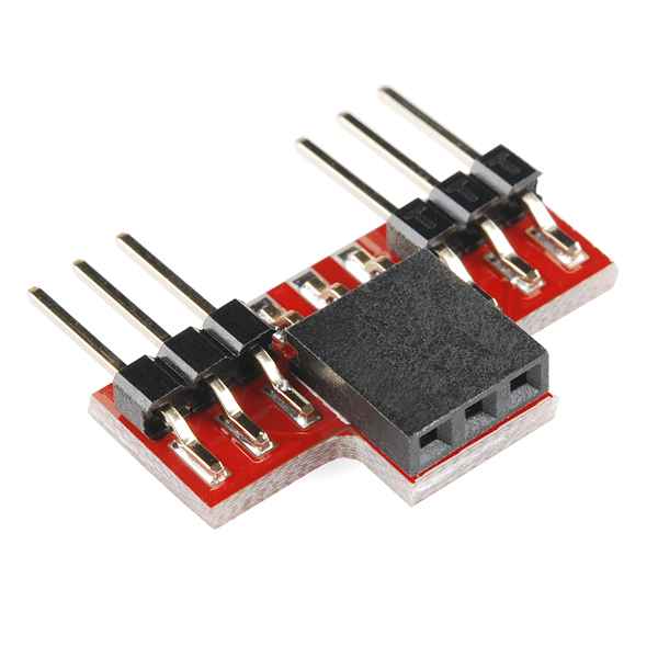
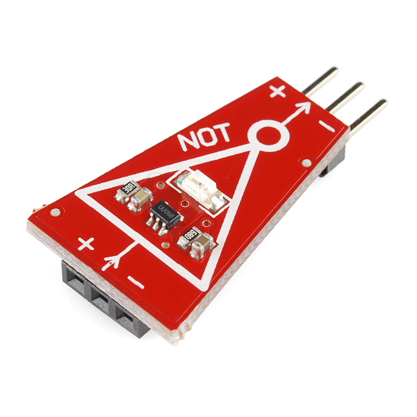
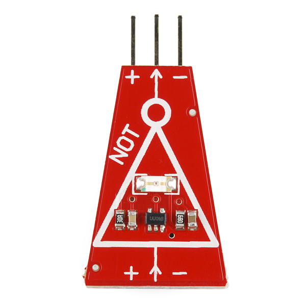
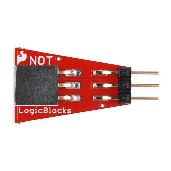
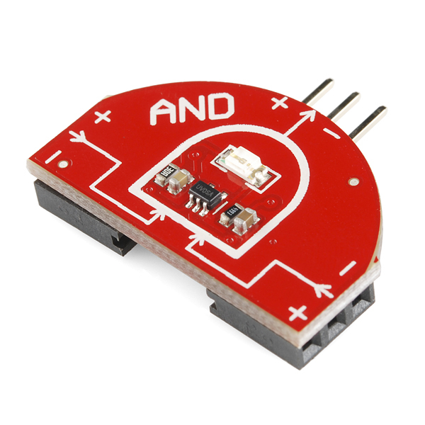
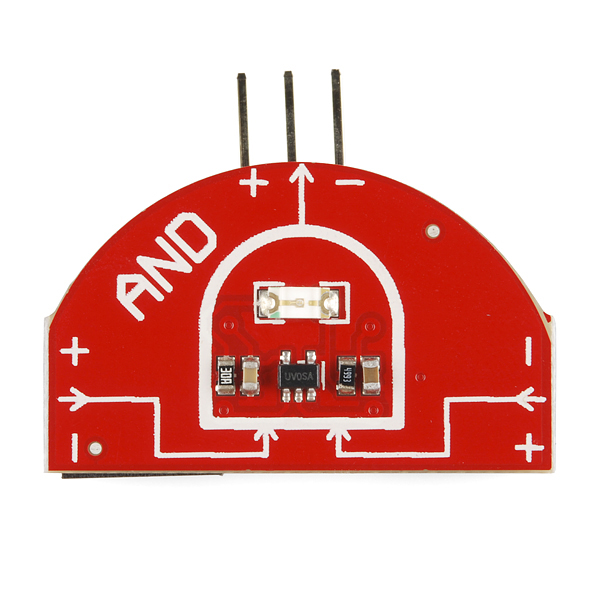
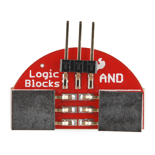
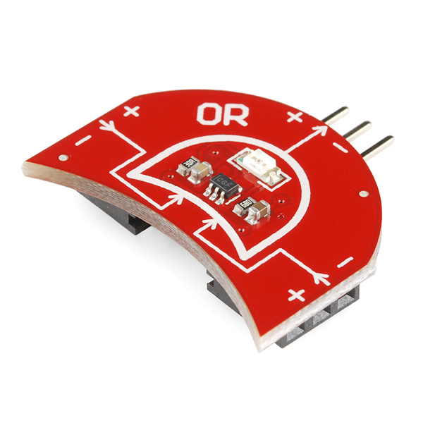
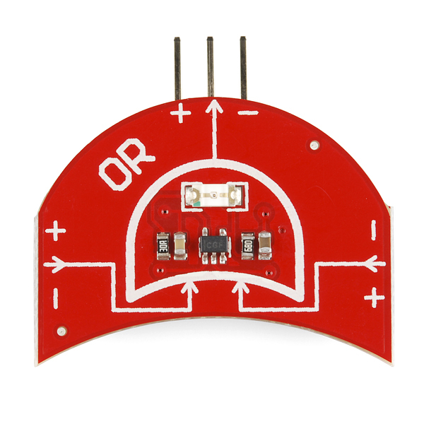
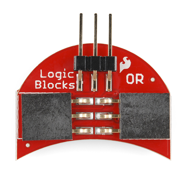
The SparkFun LogicBlocks Kit allows you to play with logic gates by literally plugging one into another and watching the progression of an input to an output! Each LogicBlock represents a different logic function: the NOT block is a simple inverter, where the output is the opposite of the input. The AND block will only output a 1 if both of the inputs are 1. The OR block will output a 1 if either of the inputs are 1. There are also input blocks and splitter blocks.
Each block has a light on board that will light up to represent the 1 or "true" state with a slight delay from the input signal. This way, you can flip the switch on an input block and follow the propagation of that signal through your logic tree. This delay also allows you to use the Feedback cable to generate new inputs based on the output of your logic circuit!
These things are seriously fun, even if you don't know anything about electronics, and playing with them is the ultimate hands-on course in logic gates. This kit also includes our LogicBlocks Experimenter's Guide which explains the basics of digital logic and the function of each block.
Note: This item may take longer to process due to battery installed in the equipment and therefore does not qualify for same-day shipping policy. Additionally, these batteries can not be shipped via Ground or Economy methods to Alaska or Hawaii. Sorry for any inconvenience this may cause.
- 3 x Input Blocks
- 2 x AND Gate Blocks
- 2 x OR Gate Blocks
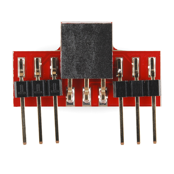
- 3 x NOT Gate Blocks
- 2 x Splitter Blocks
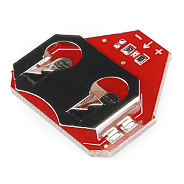
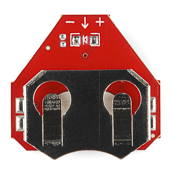
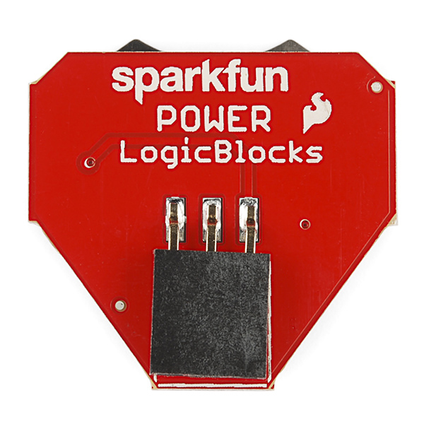
- Power Block
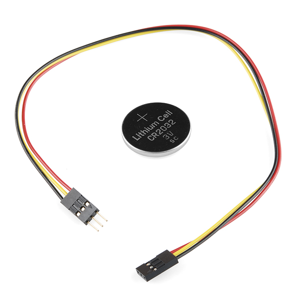
- Feedback Cable
- Coin-Cell Battery
- Schematics
- Eagle Files
- QuickStart Guide
- Experimenter's Guide
- GitHub (Design Files)
SparkFun LogicBlocks Kit Product Help and Resources
LogicBlocks Experiment Guide
March 31, 2014
Experiments guide for the LogicBlocks kit. Build oscillators, latches, multiplexers and more with the LogicBlocks.
LogicBlocks & Digital Logic Introduction
March 31, 2014
Introducing fundamental digital logic concepts and LogicBlocks
Core Skill: Electrical Prototyping
If it requires power, you need to know how much, what all the pins do, and how to hook it up. You may need to reference datasheets, schematics, and know the ins and outs of electronics.
Skill Level: Noob - You don't need to reference a datasheet, but you will need to know basic power requirements.
See all skill levels
Comments
Looking for answers to technical questions?
We welcome your comments and suggestions below. However, if you are looking for solutions to technical questions please see our Technical Assistance page.
Customer Reviews
3.3 out of 5
Based on 4 ratings:
Not exactly what I expected
I thought the blocks would be about 3-4 inches in size, they were much smaller. I had intended to use them in front of a class. They are fairly flimsy. I also wanted to make a half adder out of them, but the output is limited to one digit. Also the bracket holding the battery has come off and I do not see how to reconnect it making the whole thing useless. The idea is good, but the implementation is bad.
Hi, You're correct in that these are fairly small. They are about the size of a quarter, maybe slightly larger. As for your battery board, it sounds like the battery holder was damaged. Contact us and we can help you with this. https://www.sparkfun.com/returns
These are pretty cool and affordable!
As a techie mom, I have looked at many products that could be useful to teach programming and technology to my child and to classrooms. These blocks are a breath of fresh air in a room that only seems to blow out overpriced barely usable detritus. I will use them with my son, and I will show them to some teachers to see if there is a way to incorporate the into teaching in classrooms. They may be small, but they are great teaching tools!
A novel memory latch with SparkFun LogicBlocks
I used the LogicBlocks to demonstrate a novel memory latch (AND/OR and a>b latches). It worked great. See a clip of the (a>b) latch realized with the LogicBlocks around minute 20 of a Youtube lecture on the subject of feedback latches at https://www.youtube.com/watch?v=gRoDuz5iRys .
Especially the LEDs are very helpful to indicate the states of the circuits. The On/Off switches are a bit awkward to operate. You really cannot easily switch rapidly through many input states. The connection system works well for me in my simple designs, but I can see that one can easily lose track of a design.
I wanted blocks that demonstrated in a visual way their logic functions. That is: I did not want a breadboard with wires and chips that cannot show intuitively what the functional design is. For that purpose the SparkFun LogicBlocks work very well. The only reason that I did not give 5 stars is that I would have liked an (a>b) block instead of an AND with an inverter at an input. But non-commutative logic functions are not widely used and I cannot blame SparkFun for that. Very good product for its intended purpose.
If you just want to see how a modified AND/OR latch (yes, not your well known NAND or NOR latch) operates in SparkFun LogicBlocks, see this brief Youtube video at https://youtu.be/rPKJPfI1Euk.
I've used these kits to teach logic to small groups - they are great - it really helps when students can get their hands on things and experiment.
I have a few suggestions for improvements:
It's really easy to plug these guys in upside down, or misalign the pins. It can also be confusing for young students to have three pins at each connection. In order to be able to concentrate on the logic itself, it'd be really helpful to have a connection that can't be plugged in wrong.
Can the back be a different color? I'm considering taking a black marker to the back of my chips. This relates to #1 - I've seen many students plug these in upside down. Having an easy visual guide for which side is right side up makes a lot of sense.
XOR gates - with the addition of two XOR gates, we could build a full adder!
The LogicBlocks has indicators to where you should connect them. And the feedback cable has both a male and female connector
Just opened these up today with my 7yo daughter; she jumped right in! http://bit.ly/U3r1A3 I'll be honest, I bought them for ME initially to learn more about logic gates, but this may be another "toy" I have to yield to the little ones. I still plan to go thru the lessons on here, which are what sold me on the kit. My daughter asked, I swear, without being prompted "I wonder if a NAND is the same as an XOR..."
What I'd love to see: same product but in plastic blocks + magnets, so even littler kids could play with these things w/o them breaking.
NAND is not the same as XOR. You can create a XOR with a few NANDs though.
@Member#385408 I thought the same thing and I'm actually working on that sort of product right now. Look for it in the near future!
(member 385408 here): we put together the XOR after someone at the college EE expo explained how (spoiler alert if you want to figure it on your own): http://i.imgur.com/PE2Ecfl.jpg
I kind of wish we'd held out to figure it out on our own, but it was rewarding nonetheless!
Very cool idea. I hope it comes in a little bright red box of its own like the kits.
I will make certain to get some accompanying foam-tape weather stripping to make feet over the exposed soldering on the pin side of the boards. Or maybe some clear nail polish - nah, not obvious enough that it's there guarding the circuits. While important to learn, this kit is far too pricy to be the thing which teaches that small conductive things on the table short out and emit smoke from circuits on bare PCBs. (And being SMD, fried chip replacement would be a bit of a pain. But at least the schematics are there to tell me which part to order.)
While I'm amused by the use of a CR2032 as the size indicator, there are two things to note: Why not every picture instead of just the cable picture? And the rulers are still more helpful!
check the video today, it gives you a good idea of the size of all the parts.
This is pretty darn cool. Might just have to pick this up for the neighbor's kid who is having lots of fun with the protosnap I got him but is starting to consider additional logic components. Would be easier to experiment with these (thanks to the indicator LEDs) than with the logic ICs directly.
Yeah, I just got to play with these while I was writing the product description and I got seriously side tracked. I know my way around a logic device but these are just plain fun.
I think we need a drop test on these. I'm afraid once one falls it will go warp speed and hit the wall behind me and disappear forever...
This would be great to teach negative logic: As in making a OR gate out of an And gate.
One QUESTION: What's up with the orientation of the inputs? They are on the side. Why not line them up so it could have been bread boarded?
I was going to buy a pack of these but I can't bring myself to drop $40 on a few basic gates. But if you do buy a pack of these, I recommend checking out the following topics: Truth tables and converting to sum of products equations, DeMorgan's Theorem/basic boolean algebra, Karnaugh maps. You can actually make useful combinational circuits with those skills.
I have made a logic gate building block kit called TINION http://www.tinion.com/. I started it by 2010 and took some time to give the best. In my opinion, I refrain from giving kids a PCB to handle on their own (unless they are really really interested).
i want to see some one make a CPU out of these!
Just once i would like to get more than half way through a project before finding out you have just released the same thing as a kit.
Quick review after 2 evenings toying around with this kit with a 9-year old.
This kit is great! It is a bit pricey, but if you or somebody you know is new to digital logic and/or only has experience with software boolean logic, it's a great kit to demonstrate several principles.
The booklet is very informative, definitely a great introduction. It goes over the points of the QuickStart guide and then some with clearer graphics and more detail. I do recommend putting the Experimenter's Guide on screen (or print it out if you have a problem with trees) as it's the natural next step if you're not sure where to go from having read the booklet/QuickStart Guide.
The blocks themselves are fairly well-made, with their shapes roughly resembling their schematic equivalents and the output LEDs color-coded to the function of the block (red for NOT gates, yellow for OR gates, blue for AND gates and green for the input blocks).
The shapes' layout, disparate sizing, and inclusion of only 1 cable (3-pin jumper wire, search for SFE's offerings, not in related products list at this time - referred to as a Feedback cable in this kit) does make some layouts challenging either because you just get stuck with a port being 'blocked' by another board, or because they physically don't fit well (an OR gate next to a NOT gate on a Splitter can result in the OR and NOT crashing into each other).
Similarly, the SMD headers may be fairly far 'in' on the board, making it seem like a solid connection is not easily made between some boards. However, none have failed to make a connection and by preventing the the pins fro being inserted all the way, disconnecting the Blocks is very easy. The male headers also have tiny sleeves that can be wedged loose pretty easily; glue them down or just remove them altogether if this happens to you and bothers you. With some soldering of your own headers you might be able to make the LogicBlocks breadboard friendly, but the boards are not designed with this in mind.
The tiny switches on the Input blocks can be a pain to switch, especially if you have no nails. The tip of an old pen with the actual pen cartridge removed provided relief there.
The LEDs on the blocks are great, especially in combination with the delays, as you can easily see the signal 'propagate' throughout the circuit. The only time this is not true is when you use the Feedback cable, as its signal input may be on one side of the layout while the output is on another side. Adding an LED on each input may be a bit much (Christmas tree!), but a simple logic indicator board that could be put between a board and the cable would be a nice addition. This propagation feature alone makes it a ton of fun to play with and is essentially what sets this apart from any other logic kit I've seen in the past. You can even demonstrate how an addition of a block in place X instead of place Y can cause timing issues further down the circuit that you may not have anticipated. In actual logic components this is of course on the order of teensy fractions of a second, but if you're doing high speed signaling that just might be enough to present design decision issues.
In building some of the examples my 'apprentice' ran only into two issues, one which he later realized was what was being warned about on page 9 of the booklet (floating inputs - these Logic Blocks show the effect of that quite easily with output states switching even just by hovering a board close to a desk. That really hammered down the notion that you should not leave pins floating more than any text had so far.) and the other being with the Ring Oscillator example. It requires all 3 of the NOT gates and one of them showed the correct state on its LED, but did not seem to give the correct output state to the next block (tested using an OR block and a second Input block). I asked him to identify what the issue could be, and it took him a while but eventually he spotted one of the SMD components being only soldered on one end.
While this meant that the ring oscillator was only functional if pressing the component down (since soldered down), it did make an interesting challenge in Experiment 9 of the Experimenter's guide. In it a XOR circuit using 2 NOT gates is transformed to an XNOR using a 3rd NOT gate. Since the 3rd was having hardware issues, alternatives had to be found, and he put together a few. I have added a write-up of one of them and some of the follow-up questions, you can find the link in the Experimenter's Guide comments.
All in all this kit was well worth it. He learned several concepts and gotchas that did not necessarily apply to software boolean logic (which he was more familiar with). Hopefully LogicBlocks will be extended in the future, but he's already looking forward to day 3 with the kit so he's certainly not done playing with what's there yet!
Summary * Pro: Well-conceived kit, Easy to use boards, LED indicators with delay are brilliant, documentation * Con: Slightly limited, disparate shapes can make layouts challenging, switches can be aggravating. * Rec: Add a signal indicator block (for use with the feedback cable - perhaps include 2 of each), add PTH pads that would allow easy modification for breadboard use - provided there's enough demand, expansion kit(s).
I'm super impressed with this kit. I wouldn't buy one for myself but I would certainly buy one for beginners to help aid in teaching. I'd expect this kit to fly off the shelf if there is a high demand for teaching young students digital design. Thumbs up!
So with the next Kit(s) why not add these to your list of parts: quad 2-input AND gate (74HC08), quad 2-input NAND gate (74HC00), quad 2-input OR gate (74HC32), quad 2-input NOR gate (74HC02), hex INVETER {NOT} gate (74HC04), synchronous up/down binary counter with clear (74HC193), BCD UP_DN Counter (74192), 4-line to 16 decoder (74HC154), Dual D Flip-Flop (74HC74 or 74HC175), One of the JK Flip-Flops (74HC76), BCD(Decade counters) (74HC90), and 8-Bit Shift Registers (74HC164 or 74HC595). also some type of logic with an open collector outputs (74LS01 or 74HC33)- to drive something like a buzer, light, relay, Motor, or something else.
{Yeah I know you have the 74HC595 but you need to add LED's to the outputs and maybe to the clock and the SER IN too.}
Also you guys need to add a 555 timer to the list too- This needs to be open enough so you can make a clock but also take advantage of all the things the 555 can do too. {See Forrest MIMS' Engineer's NOTEBOOK PG112-115}.
I still like to see the LED's on the outputs on these chips. That way Kids or Adults could wire things up in the Forrest MIMS' books that SP carries, and see the output of what their making.
I still think these single logic examples are important to give an example how things may look inside the quad packages. But add these parts to your list too. Just make sure whatever you guys do, make sure you can plug them into a bread board. It makes no sense to have a rat's nest all over the place. Just Like Forrest says on page 99 of "Getting Started in Electronics" : "For Best Results, Plan the Project carefully. A neatly assembled Project will be more reliable than one hastily assembled."
This would be like what Heath Kit used to do.
By chance are you using TI's little logic? Also, Have you considered using configurable logic gates? Would cut down on the need of stocking multiple parts.
As in CPLDs or FPGAs?
As in configurable gates: NXP / TI / Diodes
I noticed you seem to have found discreet logic gates rather than quads. I tried to find the datasheets but Google just gave me results in Spanish.
Can you give us links to the datasheets?
Certainly, here's the part numbers for ya:
If you're just looking to source single-gate tiny packages, then judging by one of the Eagle files, at least one supply might be the NXP PicoGate logic gates series. No idea if those are actually what are on these boards :)
It is just handy to know. There is nothing worse than needing a single logic gate and having to use 4 or 6.
No love for the XOR? Would there be flip-flop bits in the future?
I secretly hoped the kit would be nothing but a big sack of nothing but NAND gates. I wouldn't be surprised to see XOR show up in the future.
You guys should make supplemental kits of gates. For example separate packs of 10 of each gate (including XOR, NAND, splitters, etc.)
Pulse generator (clocked no faster than the propagation delay, of course), shift register (parallel outputs), counters... might get a little beyond the scope of what this kit is for, but would be so much fun. Plain square boards would be more economical there, though :)
I bet you guys have already figured this out, but why not do a proto-snap of this? Doesn't look like you're doing a lot of interconnectivity.
Also, I had an idea and started doing a board layout for a breadboard to act as inputs (5 discrete) and 1 clock and 1 reset signal, 5 LEDs for outputs, with an optional buzzer for noise. With the clock, it had two modes a free-running clock, and one where you control it with a switch. Not sure if I will continue the layout/design of this, but just gives you all an idea of what I was trying to do to teach logic.
I know you said this was for beginners, but the thought that immediately occurred to me was that a tutorial on the use of Karnaugh maps would also be helpful. I've also used logic algebra, but mostly thought K-maps were easier to understand in the long run.
It's just that it's relatively easy to piece together logic blocks and make very complex designs. The truly difficult part is figuring out which parts of the design you can throw away to simplify the outcome. Just a thought...
I am thoroughly impressed. This is a good idea for beginners to understand things like simple logic cells. A little expensive but its not like I could design anything cheaper and maintain the value of a kit like this.
PS:(May be removed at anytime) Some picture links are broken, latest version of Chrome if that helps you.
Thanks for the heads up on the broken images! I also have some broken image links. We'll fix it as quick as we can.
Thanks also for the feedback on the price. While the ICs are relatively cheap, the number of parts, the odd-shapes PCBs, cable, and included materials all drive up the price ever so slightly. We hope this kit is a valuable tool for beginners to learn digital logic. All in all, we're pretty proud of it. I certainly could have used it when I was learning what a NOR meant in the real world.
Yeah, NO idea why the images are doing that... They look fine in our system. I'll check into it.
Can your new Pick-and-place automatically work with both sides of the PCBs, or do you need to flip them over to do the other side?
Both our old and our new P&P work the same way: We stencil solder paste to the PCB, apply components and reflow the boards in our oven to solder the components down. For double sided designs, we then repeat for the 2nd side - stencil, place, reflow. The pick and place machine doesn't place both sides at the same time.
Neat. Doesn't that mean you'll end up cooking the boards (the second time) with components face down on the oven? I guess the components are heat-resistant enough to survive that (not the headers of course, I'd guess the headers are reflowed on during the second reflow).
Yep - one side gets cooked twice. The headers are actually very heat resistant (if they survive the first trip they certainly survive the second trip through the oven.
The surface tension of the solder is actually quite large and holds the components on the underside in place. On more complex 2-sided designs, we will reflow the side that has the small components first, and then mount the larger components for the second run through. Here's a decent example.
Wow; I learn something new every day. http://www.youtube.com/watch?v=rNlSv4SUYWo