- Home
- Product Categories
- Development Tools
- ProtoSnap - MiniBot Kit

ProtoSnap - MiniBot Kit
Replacement: None. We are no longer carrying the MiniBot Kit in our catalog but we have released the new RedBot Kit instead. Go check that out if you are looking to start experimenting with robotics! This page is for reference only.
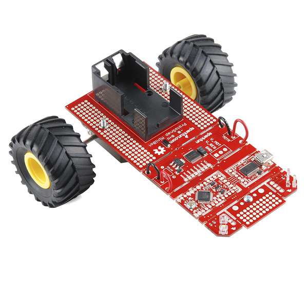
Do you want to explore the field of robotics but don't know where to start? The ProtoSnap MiniBot is a low-cost introduction to robotics for hobbyists, students and educators. The MiniBot is an Arduino-compatible platform which makes it ideal for people just learning to program as well as experienced Arduino users. And since it's built on the ProtoSnap architecture, once you've exhausted the potential of the kit as-is, you can break it apart and use the components to make other robots.
The ProtoSnap MiniBot is designed to act as a versatile platform for teaching and learning robotics by providing an Arduino-compatible controller, motor controller board, IR proximity sensors and lots of prototyping space all on one simple board. It even comes pre-programmed with a simple obstacle-avoidance sketch which calibrates the IR sensors to the ambient light then rolls forward until it detects a wall, then turns and keeps on going.
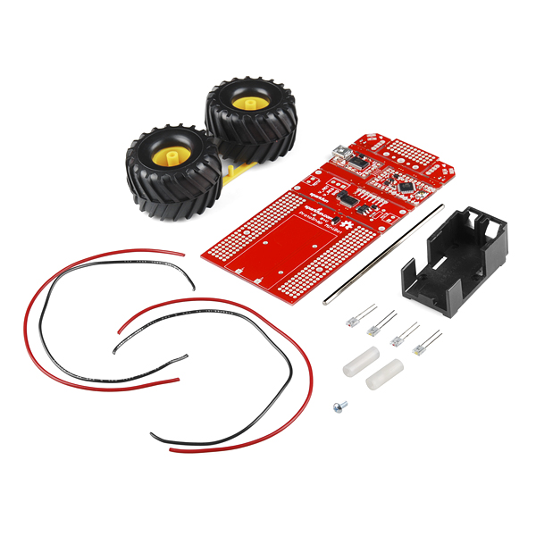
This kit comes with everything you need to get your MiniBot up and running, including an assembly guide with step-by-step instructions. You can also check out the tutorial below!
Note: Remember, MiniBot is Arduino-compatible! Download the Arduino IDE to get started programming. Also, you'll need to download the FTDI drivers before you can connect it to your computer, you can find that download link in the documents below.
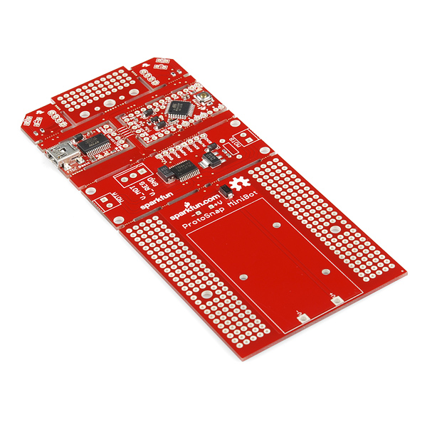
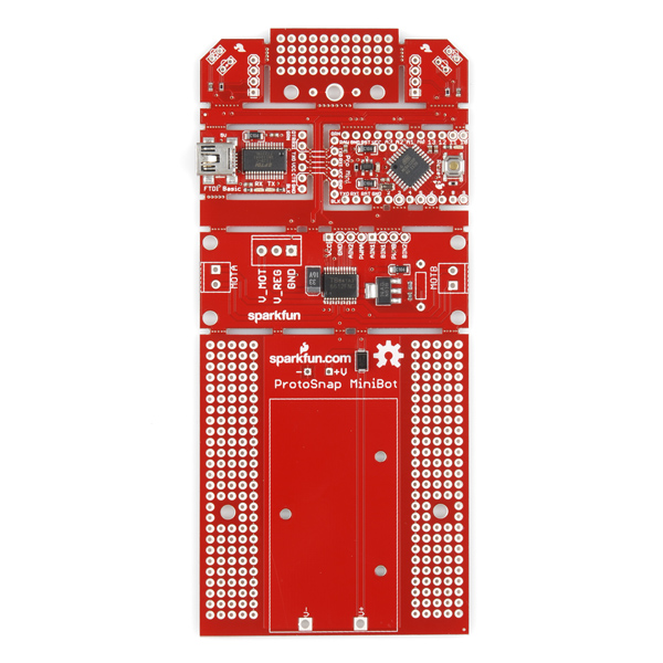
On the Board:
- 5V Uno-compatible Pro Mini microcontroller
- FTDI Basic Breakout
- 2 x IR Sensor Breakout
- TB6612FNG Motor Driver Board
- Prototyping Area
- Mounting Holes!
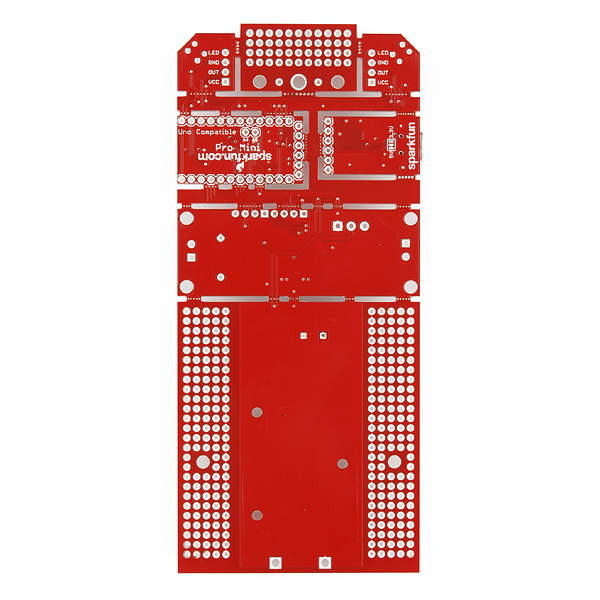
- ProtoSnap MiniBot PCB
- 9V Battery Holder
- 2 x IR sensor pairs
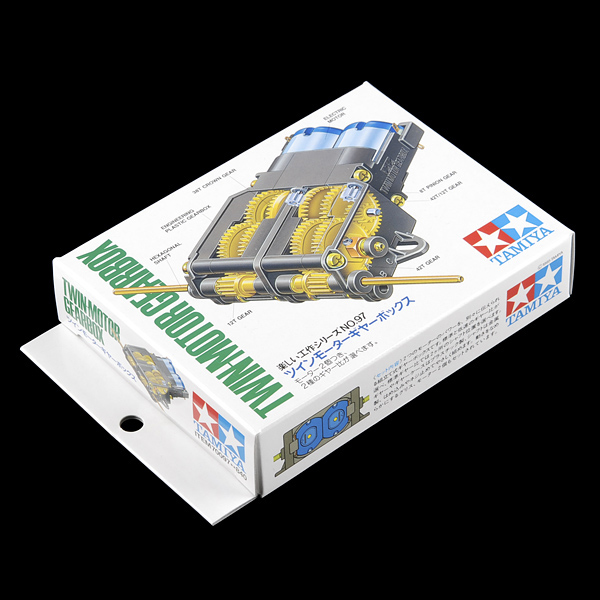
- Tamiya Twin Motor Gearbox
- Tamiya Toy Tires
- Motor Wires
- Front Standoff
- Assembly Guide
- Schematic
- Eagle Files
- Datasheet (TB6612FNG)
- FTDI Drivers
- Arduino Software
- [Assembly Guide](http://cdn.sparkfun.com/datasheets/Kits/SFE.03.0010. Kiitcard.ProtoSnapMiniBot-WebVersion-01.pdf)
- Tutorial
- Remote Control Tutorial
ProtoSnap - MiniBot Kit Product Help and Resources
Core Skill: Robotics
This skill concerns mechanical and robotics knowledge. You may need to know how mechanical parts interact, how motors work, or how to use motor drivers and controllers.
Skill Level: Noob - You will be required to put together a robotics kit. Necessary parts are included and steps will be easy to follow. You also might encounter basic robotics components like bearings, mounts, or other hardware and need a general idea of how it goes together.
See all skill levels
Core Skill: DIY
Whether it's for assembling a kit, hacking an enclosure, or creating your own parts; the DIY skill is all about knowing how to use tools and the techniques associated with them.
Skill Level: Noob - Basic assembly is required. You may need to provide your own basic tools like a screwdriver, hammer or scissors. Power tools or custom parts are not required. Instructions will be included and easy to follow. Sewing may be required, but only with included patterns.
See all skill levels
Core Skill: Programming
If a board needs code or communicates somehow, you're going to need to know how to program or interface with it. The programming skill is all about communication and code.
Skill Level: Rookie - You will need a better fundamental understand of what code is, and how it works. You will be using beginner-level software and development tools like Arduino. You will be dealing directly with code, but numerous examples and libraries are available. Sensors or shields will communicate with serial or TTL.
See all skill levels
Core Skill: Electrical Prototyping
If it requires power, you need to know how much, what all the pins do, and how to hook it up. You may need to reference datasheets, schematics, and know the ins and outs of electronics.
Skill Level: Competent - You will be required to reference a datasheet or schematic to know how to use a component. Your knowledge of a datasheet will only require basic features like power requirements, pinouts, or communications type. Also, you may need a power supply that?s greater than 12V or more than 1A worth of current.
See all skill levels
Comments
Looking for answers to technical questions?
We welcome your comments and suggestions below. However, if you are looking for solutions to technical questions please see our Technical Assistance page.
Customer Reviews
No reviews yet.
I got seven of these PCBs/panels from the Scrap Boards, and I want to break a few of them apart to solder up the Arduinos as AVR boards (practice never hurts). Where would you guys (Sparkfun or anyone else knowledgeable) recommend looking for the parts, especially the SMD crystal/caps package? Same type of question for the FTDI basic included.
Digikey, Mouser, and Future Electronics can be good starting points. You may want to check the forums as well- other folks on there may have additional suggestions for you.
You guys rock, being open source and open in general, yours and Allison's responses help a lot. I went wrong assuming these were crystal oscillators, when in fact they're ceramic resonators, which more commonly have included caps. Thanks so much!
Glad we could help you out!
someone (sparkfun gurus) could add code to show how this robot could follow lines too, please, with the sensors https://www.sparkfun.com/products/9453
For anyone who's used this, or even just the wheels/gearbox...how's the balance? Just, seeing as it has two wheels...I'm curious how it may work as a starting point for a simple-ish "Segue-like" standing robot. Anyone? Any thoughts? Thanks!
Works great! For the next iteration, though, you may want to consider a power switch — removing the battery every time you want to revise something is somewhat inconvenient.
Any tips on hacking a power switch into the existing board? It looks like the power comes straight off the battery holder into the PCB, which forwards it onto the rest of the unit. Maybe bend the battery holder connectors outward, and then wire from there to the open holes, and wire in a switch back to the Vin/out holes on the in front of the battery? Or perhaps wire a switch into the Arduino and check for state in software before going into drive mode?
I'm surprised you didn't use ATmega32U4 for the uC. It seems more compact and cost efficient. Maybe a future version with this chip? It just seems odd to me.
We may consider that for future versions; however, at the time this board was developed, 32u4 support was not native in the Arduino IDE and we wanted things to be as simple as possible, since this board is aimed at beginners and educational settings.
I agree, plus this would allow more room for other extras, such as an xbee breakout
It looks like you should try not to let this get near a stall for too long. The stock Tamiya motors have a stall current around 1.8A, and the motor driver is rated for 1.2A continuous (per channel). The driver is spec'd to a peak current of 3.2A, and has thermal shutdown, so it should recover just fine. But if you have a "heavy" load or run into a wall, it might not respond in the expected way.
Shouldn't this sucker also have some sort of flyback diode just for good measure? Tell me if I'm wrong, but motors have inductive tendencies, and therefore are risk to flyback. This is designed for education, and a simple thing like this could mess up the unit.
You're right, and the board is right too. The driver IC has integral flyback diodes.
Question: am I reading the circuit right that the motor voltage is being adjusted to about 1.6 Volts?
It's more like about 4.5V. The problem was quite simply one of balancing the low voltage rating of the motor with the power dissipation of the regulator.
There is a spot for a through hole resistor on there if you want to alter the voltage to the battery, but be aware that the motor driver has a lower bound to the drive voltage.
Hmm.... Drop, snap, break? No more robot?
While I wouldn't be too rough with it on purpose, the ProtoSnap perforations are actually pretty sturdy, it takes a good amount of effort to get a break. It's just a few close drill hits, but PCBs are a composite material so there's still a lot of structure in between.
Good to know.
Finally, weeks after the class was announced and held, the ProtoSnap MiniBot is available to the world beyond convenient driving distance of Boulder, CO!:)