- Home
- Product Categories
- Audio Boards
- SparkFun Mono Audio Amp Breakout - TPA2005D1

SparkFun Mono Audio Amp Breakout - TPA2005D1
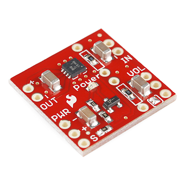
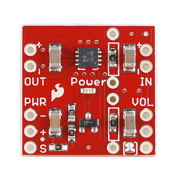
This tiny audio amplifier is based on the Texas Instruments TPA2005D1. Its efficient class-D operation means low heat and long battery life. It can drive an 8-Ohm speaker at up to 1.4 Watts; it won't shake a stadium, but it will provide plenty of volume for your audio projects.
The fully-differential inputs are safe for floating audio signals such as from our MP3 Shield, and can also be connected to ground-referenced signals as well. A shutdown input is provided to save power when the amplifier is not being used, and a solder jumper and header are provided to connect a volume-control potentiometer (not included).
Note: The amplifier's class-D design outputs a 250kHz PWM-like signal that is restored to an analog voltage in the speaker's coil. This is what makes the amplifier so efficient, but because of the switching frequency, you should keep the amplifier as close to the speaker as possible to minimize possible interference.
- Extremely efficient class-D amplifier
- 1.4W into 8 Ohms
- 2.5V to 5.5V supply
- Fully differential audio inputs, can be ground-referenced as well
- Shutdown input with pullup and LED-follows-shutdown circuitry
- PTH pads provided to change gain resistors if desired (see datasheet for details)
- Solder jumper and header allow addition of a 10k volume control potentiometer (not included)
- Schematic
- Eagle files
- Datasheet (TPA2005D1)
- Quickstart Guide
- GitHub
SparkFun Mono Audio Amp Breakout - TPA2005D1 Product Help and Resources
MP3 Player Shield Hookup Guide V15
April 6, 2015
How to get your Arduino groovin' using the MP3 Player Shield.
Making Music with the FreeSoC2
August 14, 2015
Create a synth keyboard with the FreeSoC2 from SparkFun.
TSH82 Configurable OpAmp Hookup Guide
November 2, 2018
The TSH82 Configurable OpAmp board offers the designer a great balance of performance and flexibility. We'll show you how to get the very best out of your board!
The Uncertain 7-Cube
March 8, 2013
The Uncertain 7-Cube is a non-committal, less-than-helpful, but also entirely honest fortune teller. Simply ask it a yes or no question, give it a nudge, and the 7-Cube will dutifully inform you that it doesn’t have all the facts and doesn’t feel comfortable making a guess.
Core Skill: Soldering
This skill defines how difficult the soldering is on a particular product. It might be a couple simple solder joints, or require special reflow tools.
Skill Level: Rookie - The number of pins increases, and you will have to determine polarity of components and some of the components might be a bit trickier or close together. You might need solder wick or flux.
See all skill levels
Core Skill: Programming
If a board needs code or communicates somehow, you're going to need to know how to program or interface with it. The programming skill is all about communication and code.
Skill Level: Rookie - You will need a better fundamental understand of what code is, and how it works. You will be using beginner-level software and development tools like Arduino. You will be dealing directly with code, but numerous examples and libraries are available. Sensors or shields will communicate with serial or TTL.
See all skill levels
Core Skill: Electrical Prototyping
If it requires power, you need to know how much, what all the pins do, and how to hook it up. You may need to reference datasheets, schematics, and know the ins and outs of electronics.
Skill Level: Rookie - You may be required to know a bit more about the component, such as orientation, or how to hook it up, in addition to power requirements. You will need to understand polarized components.
See all skill levels
Comments
Looking for answers to technical questions?
We welcome your comments and suggestions below. However, if you are looking for solutions to technical questions please see our Technical Assistance page.
Customer Reviews
4.4 out of 5
Based on 16 ratings:
1 of 1 found this helpful:
good power from a small package
I bought this tiny breakout board to add a little power to a surface transducer (https://www.sparkfun.com/products/10917). Its easy to solder. Remove the tiny solder jumper and add a potentiometer to regulate the volume. Works really nice.
Excellent amplfier
Works great. It would be good to have in the description the need to use resistors of about 5K ohm when shunting the board resistors for powering the 2" speaker you sell. Then everything works like a system.
good audio for arduino
It is small but gives a good loud tone. I needed to add the volume control to lower the volume. This is my audio circuit of choice for Arduino for tones and simple songs.
0 of 1 found this helpful:
Great product
Just as described, prompt delivery and professional service.
Superb fidelity from such a tiny device.
I.m just starting some projects with Audio and the TPA2006D1 is a good first step.
( How do I purchase a Dumpster Box ?) thanks GPS
Dumpster dives are a exciting phenomenon. They are randomly released, so the only way to know when they are coming is to watch the home page. Glad the board worked so well for you. Cheers!
Superb fidelity from such a tiny device.
I.m just starting some projects with Audio and the TPA2006D1 is a good first step.
( How do I purchase a Dumpster Box ?) thanks GPS
Perfect tiny amp
This is the best little breakout for a tiny project, or even a large one. Used it for a jewelry/music box with an Uno and one of your little speakers and it works just great. Totally surprised by how well it does for its size.
Works Great!
This little amp works GREAT! The only thing I did was to add the extra resistors to increase the gain to 6X. Very clear and quite loud! Love it!
Like it a lot
I use this in my Introduction to Engineering Design class, ME2300. It is taught in the Mechanical Engineering department at Worcester Polytechnic Institute so the documentation helps those who are not EE majors. We use it for a cell phone speaker attachment design project. Works great. How about adding a bluetooth chip to the board?
It was easy to work with it. I am satisfied.
Little amp works like a charm!
I've been testing a lot of Arduino based sound sources (a DAC, an FM radio breakout board, a DDS breakout board, multiple interrupt driven tone sources, etc..) and I needed a little speaker and amp to be able to hear the results. I took the little Sparkfun TPA2005D1 breakout board and built a test amplifier with a 5 volt regulator, a speaker, a toggle switch to jumper (or not) the gain option pads and, or course, an input port and potentiometer. As the product description states, 1.4 watts won't "shake the house", but it's way more than enough for my purposes, and it's very stable too. No nasty feedback or squeals at any gain setting. And, at full volume, the chip doesn't even get warm (a testament to Class D designs). Both thumbs up!
Good Amp
Tested it out in a single channel amplifer with one of the speaker on here, it had a nice volume. only bad thing is its only monochanel, you have to use it in pairs to get a stero amp. i wish there was a on board voltage regultor, had to have an eternal one.
Excellent!
Easy to set up and use. Fast shipping
0 of 4 found this helpful:
helped me add voice to my RoboGuts robot controller board ...
The audio amplifier board is the first piggyback board on my own designed µController board ... too bad it's not 5W of power and 3V-12V ...
RoboGuts
You choose the µController chip or module you want to use, then add mostly standard 3-wire hobby cables to attach to your peripherals and jumper the circuit you want, including adding a voice to your robot projects ...
This circuit board and my books make beginning home hobby robotics so much easier to learn and create/innovate ...
http://brainless.org/MultiMedia/Robotics/RoboGuts/RoboGuts+Chips&Modules.jpg
https://youtu.be/rFc5olFjio8
Excellent & Easy to use Product
I used it to build a stereo FM Receiver and it works from first try :)
See this video: https://youtu.be/a82DHU4T_aY
Circuit is using:
1 x SparkFun Breadboard Power Supply Stick - 5V/3.3V (https://www.sparkfun.com/products/13032)
2 x SparkFun Mono Audio Amp Breakout - TPA2005D1 (https://www.sparkfun.com/products/11044)
1 x SparkFun FM Tuner Basic Breakout - Si4703 (https://www.sparkfun.com/products/11083)
1 x Arduino Pro Mini 328 - 3.3V/8MHz (https://www.sparkfun.com/products/11114)
Connections and firmware are here: https://github.com/mkhuthir/repo_SDR/tree/master/Si4703
At first I had no problem prototyping with this board. However, once I soldered everything up, I started running into a strange problem: the board appears to shut down (though the power light is still on) if I turn my 10k volume pot up at all. I can only use the bottom 10% or so of the range before the sound cuts off. I'm assuming this is a thermal shutdown issue, because I can wait 30 seconds, turn down the pot a bit, and the sound will play again (though the chip is always cool to the touch). I'm powering the setup directly from a regulated 5V source and receiving an audio signal via TRRS pigtail from my laptop. Any thoughts about what I'm doing wrong?
I used this with the SpeakJet chip to make a cool R2-D2 widget. It's loud enough even with a tiny speaker. Check it out
I've found that if you grossly overdrive the board, it shuts down (requiring a power cycle). It also has an output short circuit detection circuit (which shuts it down as well), I'm sure it's not a "thermal issue", since the chip runs cool even at full power.
I would really like a stereo one for L and R speakers.
Does it fit in a breadboard?
Yes! All the headers are on a 0.1" grid. One wouldn't normally break out the PTH gain resistor replacement holes, but if you need to, they are on-grid as well.
This board is impressively well thought-out.
Why won't this amp drive the 0.5W (8 Ohm) speaker you guys sell? For me it only can drive the flat little low power speaker. It drives earphones fine and the fidelity is very good but I wanted a speaker output that sounded good not the flat little thing with low fidelity.
This drives the "thin speaker" very well but I can't get it to drive your .5W 2" 8 ohm speaker.
This amp shouldn't have a problem driving either speaker (or even much larger ones). Is it very quiet or is there no sound at all? In case your 2" speaker is defective, can you try a different one or measure any resistance across it? Contact our tech support department, they'll be happy to help you out.
Could this be used to replace a comtactmic preamp circuitry that I made in order to amplify an analog signal coming from a piezo? Also, I would like to connect the amp signal to bluetooth and have a wireless connection with a recording device... The idea is to mount it to a musical instrument and not worry about cables. What do you guys think?
Could you drive two SparkFun Mono Audio Amp Breakout - TPA2005D1 with the MP3 Player shield and the Arduino Uno to get stereo?
Is all capacitor 10uf & 1uf electrolytcapacitor???
How close does the amplifier need to be to the speaker? I want to make a multi-channel amplifier so that speakers could be placed all around a gallery, but the cable runs would probably be between 10 and 50 feet long...
I've found that any reasonable amp-to-speaker wire length radiates a ton of RF noise, detectable on AM and SW radio receivers. I made a little filter board using two 68uH series inductors and a parallel 1.0 uF capacitor on a tiny board, mounted directly to the amp board. This allows the use of longer speaker wires without spraying the whole room with RFI... and it doesn't effect the audio quality one bit.
It should work at "any" distance, but because the speaker signal is a high-power medium-frequency signal, longer runs could cause interference in nearby sensitive devices (radios, etc.). In an ideal world each speaker would have an amp close to it, and the input side would be the long one. For whichever side is the long one, do try to use shielded or twisted wire (CAT5 is cheap and pretty good for this) to minimize transmitted or received interference. Let us know how it works!
I was wondering if this would work with the large surface transducers that you guys sell. Im trying to make some awesome pranks.
Yes, it works great with the big transducer!
Hey, eagle Files are not avaible :-( please correct the Link.
Thanks
Working on getting that fixed now! Sorry about that.
This worked perfectly to boost my pwm speaker output to an acceptable level. Only problem is i get a high pitched whine. It doesnt exist in the source in, so i guess i need a low pass filter on the speaker output.
I'm using a sparkfun NCP1402-3.3V Step-Up Breakout to power everything. Can anyone give me a clue as to what value capacitor and resistor i might need to build a simple low pass filter?
Whine is sometimes a ground loop problem. You could try connecting the "-" input to ground and see if that helps.
Other than that, if your input is a PWM signal, it may be interfering with the amplifier's own PWM frequency, in which case you should try low-pass filtering the input. There are filter calculators out there that could give you a better answer, but you can start with 100 ohms and 0.1uF, which will pass everything below 10kHz. Low-pass filtering the output is harder because it is a high-power signal and needs high-power filtering components. Good luck!
I have excessive noise distortion w/ a 100 ohm resistor which I needed to boost volume. I'm thinking this might help. What is the simple schematic for this low-pass filter (not an EE)? Thanks...
Where is your 100 ohm resistor? If you're using it as a gain resistor (a pair of them soldered to the board), 100 ohms is too small. The datasheet recommends 15K (gain = 20) as the smallest but we've gone down to 3K (gain = 100) with decent results.
The low-pass filter Wikipedia page has schematic examples for a simple passive first-order RC filter.
Thanks for the tip! The low pass filter seems to be working (just need to tweak it).
Also, I wanted to drive an LED off of the speaker output and have it blink with the sound, but because the output is PWM, there isnt much blinking going on as it would had the output been analog. The LED is on and bright. Any ideas on how i might get it to blink? I read that I could use a low pass filter to convert PWM to voltage, but as you said its a high-power signal....
Do you want a simple on-off light from the LED when audio is present? Or do you want the LED intensity to vary with the sound level? Many solutions are possible, not just one. We need a bit more input form your concept to determine the next step.
Hi. I think I want to do the same thing as Mike416. Ideally, I want the intensity to vary with the audio, but I would also like the LED not to be on if no audio is played. There seems to be a ~2.5v floating voltage (ref to gnd) on the outputs which causes the LED to stay lit (I was feeding the output into a simple NPN transistor controlled LED circuit). I presume this because it is a differential output? I'm guessing I may need to convert the output into a ground reference one?
Can you suggest a solution?
Thanks.
As you've seen, because of the way the Class-D output works, this board really isn't suited for that application. I highly recommend you check out the new Sound Detector board though; it's designed to do exactly what you're looking for.
It would be nice to have a SPARKFUN data sheet with board dimensions and pin locations for those who DO NOT have software to open an Eagle file. I don't even know the size of this board.
The board is 0.8" x 0.8". The holes are on 0.1" centers; the two input/output rows are 0.7" apart. We highly recommend that you install Eagle if you're working with our boards. The free version will open all of our files and answer questions like this and many more.
How can I figure out how long I could run 15Ω headphones at a reasonable volume through this off of a 50mA coin cell? In other words, how to I calculate music-listening-level source current dissipation? It's hard for me to interpret the data sheet. Thank you!
Any answers would be rough because it depends on the specific audio and what constitutes a reasonable volume. For a worst-case analysis you could use Ohm's law: 3 volts into 15 ohms will be 200mA (ouch), which would drain your battery very quickly (15 minutes). In practice you should get more time than that because you'd never be driving the speaker all the way, but I doubt you'll get more than an hour out of the coin cell.
Is it possible to use this to amplify an arduino tone() being output to 2 separate 8-ohm/1w speakers with one volume potentiometer? Would I need a resistor between the board and the arduino to subdue its output first?
I have a surface transducer (COM-10975) that I'd like to use as a speaker for a Nintendo DSi. On it's own, the transducer is just too quiet. I've been told this mono amp would do the trick for making it louder. Do I need anything else? e.g. is the 2.5 - 5.5v power supply mentioned above an optional item or do I need to supply that? from what?
This amplifier will work well for that transducer. But it can't make audio louder without a source of power, so you'll need to supply one. You might be able to tap off the batteries or wall wart in the DSi. Or you could use a separate battery holder like this one.
Thanks Mike. :) Are there other form factors / battery types? (rechargeable) I'm thinking it would be hard to attach the battery holder to the transducer.
Sure, there are a lot of battery types, and you could also use rechargeable AA batteries in the above case. You don't need to attach the battery to the transducer, but it does need to go somewhere, perhaps in-line between your Nintendo and the transducer.
hi i am wondering if this would drive the sparkfun surface transducer (COM-10975) directly when powered via the 5V from a standard Arduino Uno. I'd like to use the Mozzi library on the Arduino to generate audio, which is output directly from one of the PWM pins on the UNO... just dont' want to have another power supply to deal with. The Uno would be powered using a standrd wall-wart kinda thing.
You should be OK at lower volume levels, but you won't be able to crank it up all the way without overloading the 5V regulator on the Uno.
The longer answer is that the Uno regulator can supply about 500mA max, and can thermally support 1W before it gets too hot and shuts down (it will turn on again when it cools off, so you won't hurt it). Ohm's law says that 5V into a 4 ohm coil will draw 1.25A = 6.25W, which is a bit much for the Uno. However that's for a constant load; audio tends to be more bursty, so you should still be able to get things working. If you run into serious problems, an external 5V regulator like the 7805 will give you 1.5A if it's heatsinked. Have fun!
What the mechanics layout ? dxf ? sizes ?
It's 0.84 x 0.84 inches for the board size. You can also find the exact measurements of all the components in the Eagle files.
I'm trying to change the TPA2005D1 package on the Eagle part to MSOP8 but I get an error that "TPA2005D1DGN has unconnected pin (G$1/GND@3)". I wanted to open the part in the Eagle library to change it but it's not in the SparkFun library. The part says it's in library "mike-temp". Does anyone know where I can the footprint for this?
Oops, sorry about that! Here at SFE we will sometimes design footprints in our own libraries, and only make them public after they're proven. I'll move it to the big repo today. Also note that there's a ULP (User Language Program) called "exp-project-lbr.ulp" or "exp-lbrs.ulp" depending on the Eagle version, that will create a new library from all the parts in a project. You can then edit parts or copy them to other libraries as you wish. This is very handy if you can't access the library that was used to make the project.
The SparkFun-Eagle-Libraries repository has been updated with the TPA2005D1 in both DRB (QFN) and DGN (MSOP) packages. The QFN package is constructed a little oddly to work around some Eagle quirks; I modified it so that both packages should work correctly now. Please let me know if you have any issues.
How much current does this board draw when playing a steady tone (without volume pot attached)? When the board is powered through the arduino 5V pin it will run for ~30s then the Arduino will reset again. I think too much current is being drawn through the arduino regulator.
Have other people successfully powered this from the arduino 5V pin?
Can you recommend a speaker to use with this? Right now, I'm using the one of these (https://www.sparkfun.com/products/9151) for my project, but it's not nearly loud enough. I'm building a prop for a costume, and I want it to be heard in a noisy convention hall. I'm afraid if I use that smaller, 0.5W speaker, I'll blow it out with this amplifier. However, my space is severely limited in my enclosure, and I am having a hell of a time trying to find a 2" or smaller speaker at 8Ohm and 1.5W. Closest I found was this, on Amazon: http://amzn.to/ZbbCmA
Will that one work, or am I safe using the smaller, sparkfun speaker I originally purchased for this project?
You're not likely to burn out our 0.5W speaker with this amplifier and "normal" audio duty cycles (the effective wattage is going to be quite a bit lower than the maximum). But you're right that it's not going to be terribly loud by itself. Some ideas for increasing the volume: Using larger speakers is the most effective solution (we've had a lot of fun with used automotive speakers), though this can be hard if space is limited. You can increase the number of speakers as long as the total resistance is between 4 and 16 ohms. And small speakers will sound much better if you can add some sort of enclosed cavity behind the speaker(s). I hope this helps, good luck and send us pictures!
Any idea why mine would mix a lot of white noisey static into the signal when it's plugged into the 1/8" output of my Macbook Pro? It works fine from my iPhone's headphone port...
You've got me... I know that apple equipment uses four-conductor jacks, which might interfere with a normal stereo plug, but the iPhone has the same jack and you say it's working fine... Could it be a ground-loop problem, since the iPhone is battery powered and isolated?
why are there 3 little holes/vias above and below the TPA2005D1? i noticed the datasheet of the evaluation board for TPA2005D1 has them too. probably has something to do with heat transfer?
Exactly right, those vias help heat get from the top of the board where the amplifier chip is, to the bottom of the board for extra heat-radiating surface area, as well as making sure the ground plane is solid as this chip can use quite a bit of power. It's so efficient it typically doesn't even run warm, much less hot.
i downloaded your eagle files but get a error message "Invalid data in file". i'm on osx. usually your eagle files work great
They worked for me just now; these were made with Eagle 6 (earlier versions won't open the new format). If that's not the problem try downloading them again, it may have just been a glitch in the Matrix.
EDIT: Kamiquasi beat me to it. ;)
true. turns out i am still using v5.11. upgrading did the trick. thanks.
Could it be that you're using an older version of Eagle? I get that error in Eagle 5.11.0, but 6.1.0, 6.2.0 and 6.4.0 all load it fine. If this does appear to be the issue and you're not able to upgrade, I could give making a 5.11 version a shot. I really recommend upgrading, though.
Does the voltage of the power supply affect the loudness of the output?
Yes, it can push more power at 5V than 3.3V. (Ohms Law is a harsh mistress.)
It looks like I've hooked this up as instructed but the sound that comes out is extremely faint (I have to put the speaker up to my ear to hear it.) I attached the R Speaker output from my Musical Instrument Shield to the input + on the Amp and the - Speaker output from the shield to the input - on the Amp. I also attached an 8 Ohm 0.5 watt speaker to the Amp's + and - output and connected the 5v pin on the shield to the power + on the Amp and connected power - to ground.
All of these connections are headers and jumper wires and I think they're all pretty secure and I've set the midi volume of the song I'm playing to almost as high as it goes. I haven't touched the volume pins on the Amp and I haven't soldered in new resistors or used the shutdown pin at all.
Do you have any idea what's going wrong here?
It sounds like you have everything hooked up correctly. At this point you have two options; make your source louder, or increase the gain on the amplifier.
The VS1053 used in the Music Instrument Shield does have a volume control register that can make it louder, but unfortunately you can't access that register from the Music Instrument Shield (the MP3 Player Shield, based on the same chip, has a more complex interface that does allow this). So you're correct, in your case changing the MIDI volume is about all you can do to make the source louder.
If that's not enough, you can increase the gain on the amplifier board by adding your own gain resistors. The Quickstart Guide at the top of this page has instructions. This will make the amplifier considerably louder and I think will solve your problem. Let us know if you have further questions!
Thanks for your help. Right now the sound is so faint that it can't be heard at all unless the speaker is pressed against your ear. Do you think changing the resistors will be enough to really make it loud or do I need a different, more powerful kind of amp? If you do think it would increase the volume that much, what resistors would you recommend?
Oh and I should add that it sounds perfectly fine when I listen to it with headphones through the headphone jack instead, in case that affects anything.
It's possible there's a problem with the board, in which case you should contact our customer service department, but if you have any 10K to 100K resistors sitting around it's worth trying first. Something in the middle of that range would be best, but anything in that range will make it louder, and you need two of the same value resistors. The factory-set gain of this amp is fairly low (2X) so this should help.
Ok I changed the resistors and also increased the velocity of the noteOn command I was using and it has improved some but is still too weak for me. I'm looking for about five times the volume I'm getting now. In your opinion, would a DIY amp with an LM386 be significantly more powerful? That's what I'm looking at now.
Thanks for all your help, I really appreciate it.
I'm pretty sure now that this breakout board is working fine, the problem is with the output from my Musical Instrument Shield.
What are some options for overdriving this?
I have a mono version of that jack. There are just 3 pins. Would you mind giving me the same instructions for the 3 pins? Sorry, I am just starting out using your products. I have not used the breakout board before.
The best thing to do is to find a pinout diagram for your jack (is it a Sparkfun part?). You could also test it with a multimeter to figure out which pins are which:
Without anything plugged in, two pins will be connected (0 Ohms). Those are the switched pins. The other pin will be your ground.
Now plug in headphones and measure between ground and each of the other two pins. One pair should read 50-ish Ohms; that pin will be your audio input. The other pair should read as disconnected, that will be the pin that goes to the amplifier input.
It's exactly like the sparfun jack you referenced, it just has 3 pins instead of 5. So I assume the ground is the same and the other two pins are switched.
I have it hooked up, but I am just getting sound on the headphones only. Sorry, I'll just ask one more time. Could you go over the connections one more time, including the grounds?
OK ;). The ground pin goes to BOTH your audio source ground, and the - input on the amplifier.
That leaves two pins. One will go to the + side of your audio source, the other will go to the + input on the amplifier.
Since you can hear the signal through the headphones, you have the connection between the jack and your audio source correct.
If nothing's getting through to the amplifier, my guess is that you don't have a ground connection, or the second pin isn't really a switchover pin. (A stereo jack without switchover will also have only three pins. Without anything plugged into it, are the two non-ground pins shorted together?)
Success! Thank you so much for your patience. Today I bought a mono jack that is transparent so I could see exactly what was going on inside. With your excellent instructions, I was finally able to make it work. And the board is still amplifying perfectly :)
I would like to include a headphone jack in my project but I am not sure how to combine the jack and this board. Obliviously, I don't want to amplify the headphones, just the speaker.
Many headphone jacks have internal switches that are connected when nothing is plugged into the jack, and disconnect when you plug in headphones. This lets you cut off the amplifier when you plug in headphones.
If you look at the datasheet for the above jack, pin 1 is the ground, and pins 2 and 5 are the L and R inputs. It doesn't explain this very well, but pins 3 and 4 are the switched outputs to your amplifier (2 and 3 are paired, as are 4 and 5). Connect your mono audio signal between 1 (GND) and 2 (signal), then connect 1 (GND) and 3 (switched signal) to your amp input.
Does this board need a resistor between it and the Arduino pin?
You should be able to connect either the shutdown or the input (ground the second input) directly to an Arduino, no series resistor needed.
This is probably a stupid question, but could I take the PWM output of this amp (with suitably reduced gain, as needed) and feed it directly to an XBee >> XBee >> Speaker type setup, or (ignoring other probable issues) are the XBee data rates too slow?
Interesting question, and not stupid at all. According to the datasheet, the switching frequency of the amplifier is 250kHz, which I suspect (but I could be wrong) is too high for an XBee (I believe the max serial rate of an XBee is 115200bps, and the maximum virtual wire rate is 1kHz). And as you suspected there are other devils in the details, such as the fact that this chip sends out slightly different waveforms to the + and - outputs to improve efficiency; ideally you'd want to send both signals, which would double the required bandwidth.
A more efficient wireless system might use an ADC on the input side to rapidly sample the audio waveform, send the binary data across the wireless link, and use a DAC to restore it on the other end. You'd want to sample at twice the highest audio frequency (20kHz x 2 = 40kHz), which the XBee can theoretically handle.
If you try any of this, best of luck and let us know how it goes!
Thanks Mike! I should learn by now not to underestimate the peculiarities of working with class D amps. But the ADC option sounds promising - I'm not looking for super high fidelity, so maybe even a µC ADC would do the trick! And don't worry, I haven't forgotten my Nyquist theorem! I'd just have to figure out how to get a reasonably fast sampling rate out of an Arduino or something...I'm hoping to avoid a standalone ADC.
Fantastic board! One question, can this board work with other speakers besides 8ohm? I have a 6ohm speaker and I was wondering if I could use it with this board.
Sorry for the late reply. We've successfully tested this board with 4 Ohm and 8 Ohm speakers (and various combinations in series and parallel), so it should work fine with a 6 Ohm speaker.
Hi, I had a few questions: 1) Would be able to cater towards a large bulk order? (between 10,000 and 50,000) 2) Can this be used in conjunction with your thin flat mini green speakers? (COM-10722)? If so, would you be able to supply a similar bulk order? 3) Can this be powered from 3.3v with around 20ma? I say this because if this can be attached to the 3.3v pin 8 from an iphone socket than i wont need an external battery. 4) Would sparkfun be able to build a custom enclosure with audio in/out so that i can sell it to my end clients as plug and play without soldering etc. Thanks
Can this power a 2 watt 8 ohm speaker? Also I'm wondering what the shutdown input is? Does it turn of the power?
Yes, and yes!
The world is saved! This saved me a good chunk of money, space in my project, and the hassle modifying my enclosure requirements. Thank you so much.
Could this amplify an electric guitar?
I guitar is about -20 dB, which is not line level (0 dB), you'd need a pre-amp stage.
If the guitar output is line-level audio, and you want to drive a speaker, then yes it should work well.
Hi - I was wondering if this would be sufficient volume to create a custom bicycle horn? A friend of mine wants a horn on her bike that can Moo like a cow - I was thinking of pairing it with https://www.sparkfun.com/products/11125 and a suitable splashproof speaker (or housing) obviously with the emphasis being on small enough to fit on a set of bicycle handlebars!
There are two things that affect how loud your project will be; the power of the amp, and the size of the speaker. If you hook up a 6" or 8" speaker to this amp, it will be fairly loud (especially if you put smaller gain resistors into the amp to increase the volume), but that speaker might be larger than you want for something that goes on a handlebar. Give it a shot, and let us know how it works!
Would this be capable of driving a pair of headphones? Nothing massive, but probably in the usual 16-32 ohm range. And yes, mono is fine...
It would work, but there are headphone amplifier circuits out there that are better suited for that task. This board is primarily designed to drive larger loudspeakers.
Can I use the output of this to go into the AUX input of my car stereo? I'm pretty sure there would be a mismatched load problem, what could be done to make it work?
Unfortunately no, the output of this board is designed only to be connected to a speaker. But is there a reason you couldn't connect your line-level source directly to your AUX input?
You could filter the output with an LC filter for devices that need a real analog audio signal. (For example http://sound.westhost.com/articles/pwm.htm). You would place the filter components close to the board.
I have not tested this but I think I may get one of these to see how well it works driving a headset.
My source is a vibration sensor. Currently I use a Radio Shack mono mini-amp to amplify it and then from its headphone jack into a car stereo AUX port. I would like a less-noisy amplifier for this purpose.
Hi,
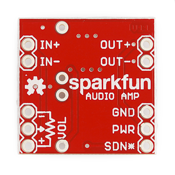
great shield, works like expected! Just a question: what's the SDN* ?
Cheers.
SDN* stands for "shutdown", if you leave it disconnected or connect it to a digital high signal, the amp will function normally. If you connect it to ground or a digital low signal, it will turn off the amplifier and LED to save power.
Thanks Mike!
Hi. I have just setup one of these amps to be used with an older version MP3 trigger. They are a great product but I had to make a breakout board for the breakout board. Would it be possible to get a new version of this which has mounting holes, like for example the way the microphone pre-amplifier board does? I know it would make it slightly bigger but it would still be a lot smaller then competing boards. If I was using an external volume control I know I could hang the board off the pot.
Thanks for making great products.
Thanks for the feedback! SFE leans towards having no mounting holes on our smallest boards, because it reduces costs (PCB real estate is surprisingly expensive), and also on the theory that most people will be plugging these into a breadboard or larger circuit board. It's also common for people to stick boards down with double-sided foam tape, hot glue, etc. That said, we're listening, and take your comments into account when designing new products. Thanks again!
how do I shutdown this amp from Arduino ? Should I simply connect the shutdown pin to a digital pin from Arduino and then set the signal to LOW ?
That's exactly how it's done. The LED will indicate whether the board is active or shut down, so you'll know if you're doing it right.
Hi, received my amp and Mp3 shield, is there a tutorial on how to attach the amp to the MP3 shield - or a quick explaination of how to do it. Thanks
Sure! The MP3 Shield has a "Speaker" header with -, R, L pins. Connect the - pin on the Shield to the - in pin on the amp. Connect either R or L on the Shield to the + in pin on the amp. That's it for the audio connections. You'll also want to run power to the amp (5V if you have it, 3.3V if you don't), and connect the amp to a speaker (at the out + and - pins). That should be all you need, ask if anything's unclear.
Hi, I have done exactly what was stated above, however the sound coming out of the (2 watt) speaker is extremely faint. I have a potentiometer attached to the amp, but does not seem to work with the mp3 shield. I have tested the amp/pot/speaker with the arduino "tone melody" example without the mp3 shield (attached to pin 8) and everything works great, very loud. But the second I hook the amp up to the mp3 shield (powered from the 5v and GND pins), I hardly hear a thing. Any thoughts? Thanks!
thanks mike, worked great. researched and connected 2 8omh speakers in series. question : mono amp is 1.4 amp and each speaker .5
how many speakers can i connect safely in series
I haven't extensively verified this, but according to the datasheet, the amplifier chip can safely handle both short-circuit and open-circuit conditions, so as far as "safely" goes, you should be able to connect as many in series (or parallel) as you wish. This won't hurt the amp, but the amp won't always be able to drive them satisfactorily.
Pete's the audio guy, but as I understand it, as you add speakers in series, the total impedance increases, so the speakers will get quieter, but the current through the amp won't increase so this is always safe. If you add speakers in parallel, you'll maintain the same loudness per speaker, but the impedance will decrease, the current will increase, and eventually the amp won't be able to handle it. I would think you could handle two (8-Ohm) in parallel, and maybe four in series? Let us know how it works!
come on Mike, just short the thing and see what happens...
you're right about putting speakers in series. impedance drops and you create a less stable load and less power to each. most amps are more efficient at a slightly higher impedance. but, if you had 2 16 ohm speakers in series, you'd have an 8 ohm load.
so, yeah, what Mike said.
You mean in Parallel? Series Increases impedance, just like with Resistors.
er, yeah. derp.
I just wanted to report that if you use this with the SOMO-14D, you can turn on and off the amp by just directly connecting the BUSY Signal from the SOMO-14D to the Shutdown on this amp... Works perfect in my testing!
What are the dimensions of the board?
0.8" (20.3mm) square. If you're ever curious, you can always get exact measurements of our boards by opening the Eagle files.
Thanks!!!!
If anybody is interested in using this to amplify the "SP" speaker port on the VEX Robotics Cortex Microcontroller, it works great! I wired it up for single-ended input (signal to - input, ground the + input).
I wanted a bit more gain so I traded the resistors for 47KΩ through-hole resistors and now my robot can get some attention!
Can the audio input to this board be modulated PWM from an arduino PWM pin?
I just tried it, it works perfectly and is VERY LOUD.
Thanks for replying Mike! When you tested, did you use a resistor to limit the voltage going into the BOB? When I test with mine I'm afraid of driving too much voltage from an arduino PWM pin to the input of this BOB.
EDIT: After looking at the datasheet, it looks like a resistor would not be needed since the input voltage is listed as being -0.3V to Vdd + 0.3V. Am I correct? Thanks again!
You're correct and beat me to it. ;) Note that for such a large input, the board will be clipping the output, but since the input was a square wave already, you don't really notice. Have fun!
Wow, sold out already!
Can you believe it?! I was just at radio shack the other day for an LM386. Seems like new product posts are always a week late!!!!
Adding a jumper to disable the LED would be a good feature to have. The LED just defeats your statement of "long battery life". (Well to those who work in the nA/uA range...)
The board could be of been made a bit smaller... but i'm not sure it matters.
The LED follows the shutdown signal, so it's off when the board is shutdown. A very small amount of power is bled through the pullup resistor, but if you're really into nA, you can remove those components.
We could have made it smaller, but thought that the PTH resistor pads were a good feature to have. And just how small do you need it? ;)
I know it's because of fab house and PnP limitations and at the same time attempting to keep all of the components on one side. I just like small devices.
Have you considered using 1206 footprint for the gain resistors? Should be easy enough to solder on.
To me, the resistor sizing is fine, just need to make it more compact. Shouldn't affect the PnP all that much (pending on Bert/Ernie's precision).
One thing that I do suggest is building some kind of enclosure for it. Since you are dealing with a wide range of frequencies, you are gonna to see noise in every spectrum, and capacitors/resistors can only do so much, and if a lot noise gets into the line you are effectively amplifying it (duh). I am not saying that the design isn't good, but for anything like this, a faraday cage would be a good product addon to have, or at least some kind of CAD design for people to use.
I know of the perfect Faraday cage that doesn't break the bank. A anti static shield bag (Not the static free blue/pink ones, a real static shield bag with metal coating).
I'm also quite surprised that SparkFun isn't listing/selling/using them. Normally less than 10 cents at quantities of 25.
Pretty cheap on Amazon: http://www.amazon.com/gp/product/B000BSHGUS/ref=oh_o05_s00_i00_details
Nice chip. Can you please rev. the layout to avoid this problem mentioned in the datasheet: "Place the input resistors close to the TPA2005D1 to limit noise injection on the high-impedance nodes."
You have the high-impedance nodes routed all over the place.
We do mess up from time to time, but contrary to popular belief, we do closely read the datasheets. This board was routed with those recommendations in mind, balanced with meeting the additional requirements of the design (supporting PTH pads for gain-resistor replacement and a header for an optional external volume control pot). The diversions are minimal, and in any case the board is less than an inch square. Finally the proof is in the pudding, as the board performs extremely well. Try it, we think you'll like it.
Thanks Mike. Indeed the proof is in the pudding so it depends where your customers install the board.
If anyone is interested in this issue for their own board designs compare Sparkfun's to this one: http://www.ti.com/lit/ug/slou134/slou134.pdf
Also if you find you want lower distortion than 10% (at 1.4W) you can get lower distortion and higher efficiency with this chip by using a higher impedance speaker: 16-32Ohms. The volume wont be as loud though.