- Home
- Product Categories
- Robotics
- Wild Thumper Controller Board

Wild Thumper Controller Board
Replacement:ROB-12075. Dagu has released a much stronger motor controller that acts as the Wild Thumper board's successor, go check it out! This page is for reference only.
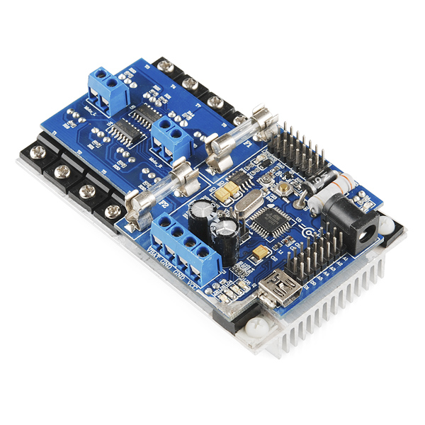
This controller board is built by Dagu specifically for their robot platforms. It essentially combines an Arduino development board with a dual H-bridge motor driver all bolted down to an aluminum heatsink. The heart of the board is an ATMega168 AVR microcontroller which comes loaded with the Arduino bootloader and some simple control code. Code can be easily accessed and changed in the Arduino IDE using the on-board FTDI chip and mini-USB connector. All of the headers on board are accompanied by ground and voltage lines to allow for easy servo connection.
The controller allows for on board charging of SLA, NiCd or NiMh battery packs and has a dedicated barrel jack socket for DC input. A 5 Amp LDO voltage regulator handles the step-down from standard 7.2 or 7.4v RC battery packs. A set of screw terminals are provided for the battery connection as well as for connecting external devices (5 volt regulated out).
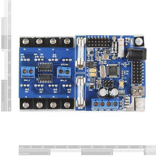
The motor controller side is made up of dual 15A FET H-bridges with fuse protection. A blown fuse is detected by the microcontroller and indicated by an on-board LED. Screw terminals are populated and clearly marked for left and right. All of the FETs are bolted down to the aluminum heatsink and electrically isolated with thermal tape.
This board is ready to go out-of-the-box! The supplied code will accept input from a standard RC vehicle receiver and handle the "mixing" for differential steering. If you would rather control it with Serial or I2C input, that can be done simply by downloading the proper Arduino sketch and changing a few constants (it's programmed in!). Also, because it is an Arduino compatible controller, feel free to write your own control scheme or even load it up with sensors and go autonomous! Seven general-use digital pins are broken out on the board as well as 5 ADC pins and the ISP header. Uploading code is as simple as selecting "Arduino Pro or Pro Mini (5V, 16MHz) w/ ATMega168" under the boards menu in the Arduino IDE.
Note: The 2 Amp on-board charging system is not capable of charging Lithium Ion or Lithium Polymer batteries. Attempting to charge LiPo batteries with this board could cause fire or injury. Lithium batteries may be used to power the board, just charge them with a dedicated LiPo charger.
- Controlled by on-board ATMega168 IC with Arduino bootloader
- Dual 15A FET H-bridges are fuse protected
- Blown fuse events are indicated by on-board LEDs
- 7 x Digital pins (D2, D4, D7, D8, D9, D10, D12)
- 5 x ADC pins (A1, A2, A3, A4, A5)
- Capable of charging SLA, NiCd and NiMh batteries
- Ready out-of-the-box for RC "servo" control on a 7.2v RC Battery (not included)
- On-board current and voltage monitoring
- Communicates via PWM "Servo" control, I2C, Serial or USB
- 4" x 2 3/8" x 1 1/4"
- Schematic
- [User Manual](http://cdn.sparkfun.com/datasheets/Robotics/Wild Thumper Controller Instructions.pdf)
- Example Code* FTDI Drivers
- Remote Control Tutorial
- Reflashing the Firmware
Wild Thumper Controller Board Product Help and Resources
Core Skill: Robotics
This skill concerns mechanical and robotics knowledge. You may need to know how mechanical parts interact, how motors work, or how to use motor drivers and controllers.
Skill Level: Competent - You may need an understanding of servo motors and how to drive them. Additionally, you may need some fundamental understanding of motor controllers.
See all skill levels
Core Skill: DIY
Whether it's for assembling a kit, hacking an enclosure, or creating your own parts; the DIY skill is all about knowing how to use tools and the techniques associated with them.
Skill Level: Noob - Basic assembly is required. You may need to provide your own basic tools like a screwdriver, hammer or scissors. Power tools or custom parts are not required. Instructions will be included and easy to follow. Sewing may be required, but only with included patterns.
See all skill levels
Core Skill: Programming
If a board needs code or communicates somehow, you're going to need to know how to program or interface with it. The programming skill is all about communication and code.
Skill Level: Rookie - You will need a better fundamental understand of what code is, and how it works. You will be using beginner-level software and development tools like Arduino. You will be dealing directly with code, but numerous examples and libraries are available. Sensors or shields will communicate with serial or TTL.
See all skill levels
Core Skill: Electrical Prototyping
If it requires power, you need to know how much, what all the pins do, and how to hook it up. You may need to reference datasheets, schematics, and know the ins and outs of electronics.
Skill Level: Competent - You will be required to reference a datasheet or schematic to know how to use a component. Your knowledge of a datasheet will only require basic features like power requirements, pinouts, or communications type. Also, you may need a power supply that?s greater than 12V or more than 1A worth of current.
See all skill levels
Comments
Looking for answers to technical questions?
We welcome your comments and suggestions below. However, if you are looking for solutions to technical questions please see our Technical Assistance page.
Customer Reviews
No reviews yet.
You don't happen to give estimates on back orders do you?
Is it ok to use the ideas in the schematic up there in a commercial purpose ?, I mean I can't find license or else ? Hope you will reply to know weather I can use that schematic and mention it in my product data-sheet as a reference or I can't do this and redesign it again with other ideas thanks :)
How many motors would I be able to control with this board?
so I just got this board and plugged in a 7.2V Ni-Mh battery. LED 2 lights up but LED 5 does not. the battery is fully charged. I dont know what to do. when i hook up the RC it does not work. Any advice? thanks
Folks, Please DO NOT buy this controller. This is not Sparkfun's fault, however this controller is JUNK.
I just got mine, initially the "battery good" light was on ALWAYS.
I uploaded the Wild thumper code and it fixed it.
It worked for 5 minutes, now the "battery good" light (led 5) ALWAYS BLINKS.
Hope someone even thinking of this controller - PLEASE save your time and go with the latest UNO and a motor shield. This controller is just headache. 5 Good minutes is how long it worked. I probably will be requesting Sparkfun to take this controller back.
Another Update:
Instead of ordering another WT controller, I found the following: http://www.atlanta-robotics.com/Dual_Hbridge_Motor_Drive.php This drives up to 30AMPS :-).
I called the number on a Sunday morning and left a message if I could get one. It just happens that the owner (Jeb) lives close to Atlanta which is not far for me. He called me back shortly and said, he could assemble it for me in about couple of hours.
So I got this and guess what? This is sooooo worth it. I went to the store and got a Mega Board and with this controller I'm back to working on my project again.
I paid $45 + $35 for the adruino mega = $80, but I think this motor driver is much awesome. I've been testing this and it works superb :-)
Couple of things to keep in mind, the Atmega chip in WD controller is old. you would need Arduinio IDE 1.02. The latest IDE will not support uploading sketch. So I'm convinced, getting this motor controller and getting the latest REV 3 is the way to go.
Update: I did find the problem with the wild thumper board - It turns out the mini USB connector is the culprit. (It came out loose). If I press really hard on it, then I could try to upload the sketch :-( (Not sure how to fix it)
If you are trying to used the Dagu motor controller with their Wild Thumper vehicle, which is great, but can't get it to respond properly to a RC transmitter, make the following changes to the software. Get off D0 and D1 and move to D9 and D10, which are PWM channels. You don't want a PWM repetitive pulses (every 22ms from a Spektrum transmitter) to clobber your serial interface when loading programs. This is why you get a sync error from the compiler if you follow the manual. Now you have to comment out the places in the code where D9 and D10 are defined as servo outputs (in variables and setup() area). Then the controller works fine. I used the aileron for L/R and elevator for F/B. This way when you let go of the control, the vehicle stops. If you're moving forward (or in reverse) an aileron right or left turns the vehicle. For a really quick reaction, just leave the elevator in neutral and kick the aileron control directly. One motor goes forward and other in reverse and you spin. A word of caution - switch off the vehicle power before turning off your recv/trans or you could send the vehicle off running out of control. Another point. If you want to see the serial monitor outputs, just change the Cmode to 0 in the "Initialize I/O pins" segment. I would also change the Brate value to 9600 in the Constants.h file so the Arduino isn't using so much horsepower just spitting out simple lines of info that you will probably want to cease once you've looked at it (go back to Cmode = 1). This info is important to see, once, because you will probably notice the motors are not balanced in power usage. Run the cal shown in the manual to get the same response from the right side motors as the left side motors and your driving experience will be greatly enhanced. [Using the serial interface to run the vehicle is insane anyway, because the slow reaction time of typing in commands - please!]
Using a Spektrum DX8, the D1 channel on the Dagu Controller runs the L and R motors forward and backward, but I can't get any direction change. The D0 channel doesn't do anything. I've used all 8 channels of the AR8000 receiver and they are all working, but only the forward and reverse work. How to I get the direction channel to work?
Can anyone help me with how to wire this with a 6 channel RC receiver? I'm a bit lost.
"The controller cannot be powered directly from the USB port. The controller must be powered from batteries or a DC supply (6-12V). If using the DC socket then current will be limited via the recharge circuit." Does that mean I can power the controller via the 2A DC recharge socket?
"This is a low voltage controller and was designed to be powered by a 7.2V sub C battery pack as commonly found in RC cars. Higher battery voltages can be used (maximum 18V DC) but will reduce the maximum current output of the 5V regulator. A small CPU fan may be mounted on the heat sink if required." If higher battery voltages can be used, why would that reduce the maximum current output of the 5V regulator?
I got stuck for a while with this board trying to power it purely from the DC socket. It sort of works but then the drivers don't install properly. Hooking the battery up while doing this solves the problem however - the DC socket seems to be for charging only
What about on board charging AGM batteries?
I'll take the no reply as a no. How come you guys aren't selling the Wild Thumper High Power Switch?
Sorry we missed your last comment! I'm not sure about the AGM batteries-my guess is this wasn't an option for us when ordering from Dagu. As far as the High Power Switch, I'll send the idea to our product sourcing guys and see what they can find out!
Just got mine but I'm seeing some strange behavior: I have two batteries. One is LiPo 7.4v 1000mAh and the other is NiCd 7.2v 1600mAh. I was using the NiCd for about 15 minutes (I have the Wild Thumper 6 wheeler) and then the "battery OK" light goes out and I'm done. Neither battery will work UNTIL I upload the demo sketch again. After that I get a few minutes of runtime (with either battery) and then again I have to upload the demo sketch to get the board to recognize that my battery is OK. My radio is a Spektrum DX6i. Also I am not using the onboard charger... I have an external iMax B6 charger.
Any ideas? Any one else seeing this? Thanks!!!
Could you make a tutorial on getting started with the wild thumper controller? I have looked on the internet and all of the demo tutorials are very vague.
Hi everybody, I bought a Wild Thumper Controller Board. After calibrating the sensor (Wild_thumper_diagnostic.pde) with the controller connected to a DC supply, and then connected the controller with the battery (12V and disconnected the DC) I got this error:
avrdude: stk500_recv(): programmer is not responding
I can't upload any program (board and port checked). My only clue is that the bootloader doesnt work anymore which I'm trying to re-install it without any success.
I appreciate any suggestion
Must install Arduino 0022 from www.arduino.cc to get the provided sketch to work Mac or PC.
On Mac OS 10.6 after you have installed the version 0022 install the provided Driver called FTDIUSBSerialDriver_10_4_10_5_10_6.mpkg it will work fine. then the newest version will see the USBserialPORT and upload sketches via arduino 1.0.3 Choose the board name "Arduino Diecimila or Duemilanove w/ATmega168"
On Window Vista install version 0022 first and send the sketch file to the board to test it. you can install the version 1.0.3 and open the sketch, it will rename the sketch to the new version called .ino and you will have to delete the older version called WILD_THUMPER_CONTROLLER.PDE then you should be able send the sketch. choose the board name "Arduino Nano w/ATmega168" have fun...
How does the board charge the SLA, NiCd or NiMh battery packs?
The controller has a current regulating circuit that limits charging current to approximately 2A. The sample code monitors the voltage across the battery terminals. If the voltage stays constant for more than 15 minutes or starts to drop then the charging circuit is switched to trickle charge (about 50mA).
The sample code was written for a 7.2V NiMh battery pack but can be adjusted to suit different batteries, for example you could change it to switch to trickle charge when the voltage reaches 13.8V if your using a 12V SLA battery.
This circuit is not suitable for LiPo batteries.
Anyone have issues with the driver output cutting out?
I'm using a 7.2v 10000mah Nihm battery, the controller, and two 7.2v gearmotors. My code is set up to run both motors at the same time at the same speed (with a modifier to make up for the slight difference in speed, simply adding 6 to one). I have additional power control as well as modified origional overcurrent protection (if one motor circut overloads, both shut down).
It was working great and I was getting the bugs worked out, and now the right motor output stalls (motor stops) intermittantly in one direction. I haven't be able to check everything yet, but I suspect on of the drivers on the H bridge. Anyone else have this problem?
My motors stall and begin to stutter as well. I figured out it was when I was trying to write from slow to fast pwm so I figured it was the over current protection. I disable the code to test and the jittering went away so I need to alter my acceleration code or adjust the current protection.
edit: actually the jittering ended up being because I didn't solder the fuses into place so an accurate current measurement wasn't happening. So solder those fuses into place!
Do you know if I could use a 6 volt SLA battery to power this?
Got a problem with this card with default firmware. I studied the code, and it seems to work properly (controller receives commands from serial port and turns on engines with functions like analogWrite(LmotorB,LeftPWM);) but nothing happens, and voltage on Moto_L and Moto_R is 0. I read, that if fuses burn, LED should light. In order to test this function I plugged off fuses, but nothing happened. Looks like ATmega works properly (serial, outputs and so on), the problem is in board. So, how can I fix it?
Sorry, at last I tried to write values to corresponding pins of H-bridge directly with my prog, and everything is fine now. So, the problem somewhere in default program.
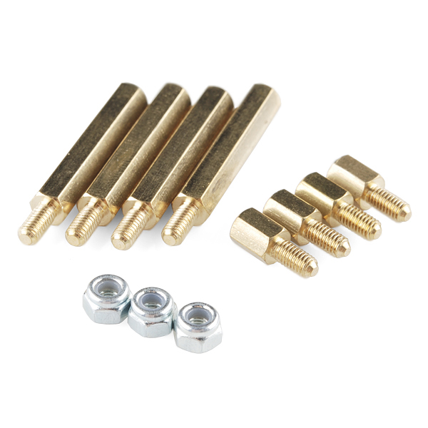
How are the included standoffs intended to be used?
any idea what 24 volts would do to this control board?
can someone please help me calibrate this thing. i dont see where the file “Wild_Thumper_Diagnostic.pde” is on the documentation. It is not very clear 4 me how to calibrate this thing. can someone help me please
Search the web for the file name and some robot sites will have it.
Could you add a video showing how to mount the Controller in one of the 2 below-deck-wells on the wild thumper?
There are no obvious places to attach aluminum stand offs to the controller. Or is there a preferred method?
2 questions: I plan to use ~6.4V to supply this board - will this cause any problems with the 5V regulator? Do I need to give it a minimum voltage to allow the linear regulator to work? Second question is how are people mounting these? I assume use the insulated screws on some of the FETs, and extend with the provided standoffs?
What bootloader are these flashed with? Because the above mentions setting arduino to "Arduino Pro", I flashed it with ATmegaBOOT_168_pro_8MHZ from the arduino bootloaders, but this changes the baud rate.
do you have a 7.4LiPo-5000 mAh for it ?or what is your recommendation?
this is intersting, but i was wondering if this controller can handle sensorless brushless motors, too? the thumper would be NUTS if each wheel was being driven a 4300kv 360 brushlees motor. or, is there a way with this board if someone wanted to do that, use a seperate motor controler for each motor, with their receiver inputs hooked into the board's outputs to the motors?
I'm getting this error when I try to upload the program to the board
avrdude: stk500_getsync(): can't communicate with device: resp=0x41
1) Arduino Diecimila or Duemilanova w/ATmega 168 selected. 2) Proper port selected. 3) LD3 & LD4 blink but then the error appears.
Any clue?
I am having the same problem, I loaded the diagnostic firmware once and the unit worked properly for sometime. When I tried to load another program arduino compiler failed reporting "avrdude: stk500_getsync(): can’t communicate with device: resp=0x41" error. and the initial program is not executing anymore.
I have tried to use ISP to load program the chip but unsucessful, I guess the Atmega168 is dead!!
Maybe I'm missing something obvious, but I'm failing to get the drivers to install for this board when connected to the USB channel. Yep, I'm going to the device manager, navigating to the adruino\drivers folder, still nothing. I've tried selecting all the various UNO, Mega and Micro versions under both the adruino IDE 1.0 and 23... still, nothing. I'm running x64 Win7. Each one will provide me with an error of: "The folder you specified doesn't contain a compatiable software driver for your device. If the folder contains a driver, make sure it is designed to work with Windows for x64-based systems."
I want to update the code because only my D0 is accepting input, and it signals both channels (both left and right side wheels spin). Which, based off my understanding and review of the code, D0 should control the right side, D1 controls the left.
I've spent more nights trying to figure this out then I should have. Any help would be greatly appreciated!
The way I read the "usermanual".... D0 is forward/reverse .. Servo output from RC controller D1 is left and right .. Servo output from RC controller.
The program has three different modes of operation, 1 - RC input, 2- Serial Input(ie. Xbee), or I2c - Insert your code here!!
If you want to drive tank style, you need to set it in the firmware to mix the channels for tank style driving.
I found that my 2 channel receiver isn't functioning on one of it's channels. If I switch the functioning channel to D0 to D1, I see a difference in direction(I swear I did this before and it didn't work, oye), (D0 controls forward and reverse, D1 reverses the direction of both drivers and powers both).
I still, however, am fighting getting the driver to load to both a Win7 x64 bit system and/or a 32bit XP system. Thanks for the help in advance.
So, I've learned a lot more about USB connections surrounding drivers and signatures in Windows. When I connect this device, it's failing enumeration, yielding an error 43 in device manager. I found a nifty tool on FTDI's website called "USB View". This let's you scan all connected devices and queries useful information from the device. When a USB device is connected to a system, that system searches the devices Product ID (PID) and Vendor ID (VID) stored on the device's EEPROM. The system then tries to match the PID and VID on the device to an *.ini driver file on the system (the driver .ini file also has these PID and VID values).
In my case, I believe the VID and PID's are not matching. In fact, using USB View, all parameters on my EEPROM on the controller come back as 0x0000. Where as, I have another device which does not have drivers installed and it has a failed enumeration, however USB View tool is still able to read the devices PID and VID.
If the USB View tool was able to read the PID and VIDs off the EEPROM on this board, I could modify the values to match within the correct driver .ini file (this is only recommended by manufactures, per FTDI).
FTDI also provides a USB tool to flash a devices EEPROM to store a VID and PID... however before I conduct a low level activity, I'm hoping for some input from some folks here.
Thanks.
From your site: This controller board is built by Dagu specifically for their robot platforms and the documentation:
This is a low voltage controller and was designed to be powered by a 7.2V sub C battery pack as commonly found in RC cars. Higher battery voltages can be used (maximum 18V DC) but will reduce the maximum current output of the 5V regulator. A small CPU fan may be mounted on the heat sink if required
Worked for 5 minutes on 12 volts and then the motors on one side went open circuit. Where can we get some new motors please?
Hey you are lucky. Mine did not detect the battery (no light on "Battery Good"). When tried to charge (12V as manual states) it started to smoke (not sure what, around the barrel connector). Then I ran the diagnostic pde - 2 motors have zero torque and they barely spin on full speed. Then 1 fuse blew for no reason (free spin 75% speed, 7.2V input). I am back to my Trex dual from pololu, waiting for new motors from pololu too.
I believe you can purchase the motors from Pololu.com If I remember right, They have two different gear ratios. I ran Mine on 12V for a while, Didnt have any issues.
Correct me if I'm wrong, but if we using this board with the 6WD model, then we are driving three motors per side, each with a stall current of 6.6A. Then won't we need at least a 19.8A motor controller to ensure that the motors will get enough current?
it works like a champ for us. we never had the slightest issue with it when driving it.
I want :)
My luck would be thou that by the time next pay comes around these ones will be sold out :(
Any idea on when more stock is coming in?
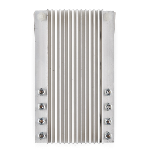
Hi guys, this heatsink just looks awesome for people needing beefy multi transistor cooling in their projects like the Ethanol fuel home made conversion kit I'm thinking of building ...
Would you by any chance have any plans / means to sell them separately ?
nope. they come attached and we're not taking them off. check ebay or aavid.
In the showcase they are using what looks like an eFlight radio system. What receiver was used? How many channels were used? Was the stun gun run through the controller board?
we just used the radio and receiver from a cheapie helicopter, not sure the model, it doesn't really matter, they all should work.
we just used 3 channels. 2 for the motion and one for the spark gap. and yes, the controller was controlling the sparker through a mosfet.
I bought the thumper combo pack, but am new with RC transmitter/receiver. Where I leave I can only find equipment for RC plane/heli. A 6-chan transmitter is somewhat pricey. Although I don't mind the additional channels, I just want to make sure I will be able to interface correctly with the motor controller. Unfortunately I cannot find any info on the receivers only (pin, protocol, etc).
That is for people like me it would be useful to have a pointer as far as the RC equipment that was used.
RC controllers are very standard. The use a standard RC protocol and pinout. Basically, you just need a radio with at least 2 channels (left and right) and that's all you need. Read up a little on RC ransmitters/receivers and you will realize it's all very easy and universal.
here is a link for a decent priced, 6 channel RC system: http://www.hobbypartz.com/79p-ct6b-r6b-radiosystem.html
it is computer prgamable.
also, i have a feeling since this board does all the mixing, a pistol grip "surface" system could be used, which would make for simple driving controls, trigger for forward/reverse and a wheel for right/left. the only downside to using a pistol grip surface radio is the number of channels. they usually only come 2-4 channel options, so any extra functions could be limited by that right there. hope this helps!
Out of stock! Bummer. SF - new product potential?
Sample receiver (with manual) found here http://www.spektrumrc.com/Products/Default.aspx?ProdID=SPMSR3520 Spektrum, JR, and a few others. 2 chan receiver prices is around $50 For info
Can the motor channels be used together to say control one bigger motor? did not find anything stating yes or no in the user manual.
Most Certainly, More than likely you would want to put them in parallel for higher current rating. theoretically you could drive up to 30A.
Yes, why it shouldn't be possible? At least when you are driving both sides the same.