- Home
- SparkFun 5-Way Tactile Switch Breakout

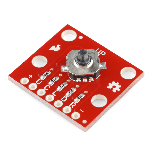
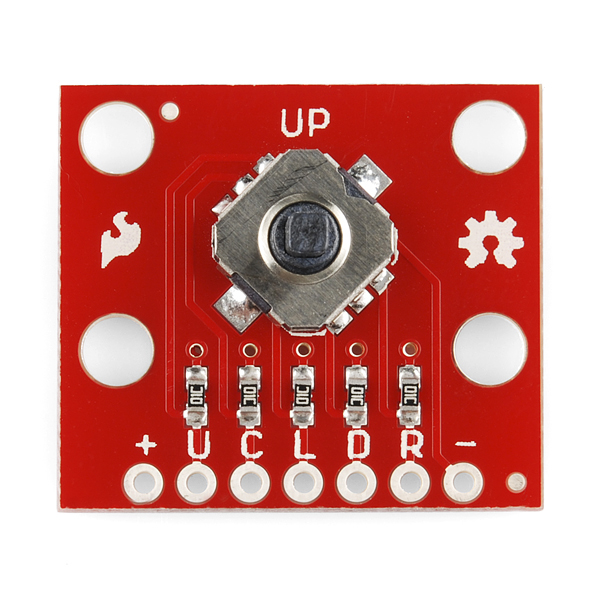
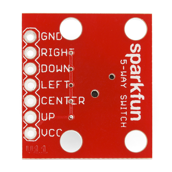
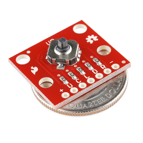
SparkFun 5-Way Tactile Switch Breakout
Sometimes you need a very small directional input device (world's smallest game controller, anyone?) This 5-way tactile switch (up, down, left, right, and center click) allows for joystick-like control in a very small package. This breadboard-friendly board breaks out all the switch signals, and includes pullup resistors configured so that the outputs read low when pressed, and high otherwise. (If you wish, you can reverse the power leads for pull-down operation.)
This version has correct labels for the headers.
SparkFun 5-Way Tactile Switch Breakout Product Help and Resources
Button and Switch Basics
May 7, 2013
A tutorial on electronics' most overlooked and underappreciated component: the switch! Here we explain the difference between momentary and maintained switches and what all those acronyms (NO, NC, SPDT, SPST, ...) stand for.
Core Skill: Soldering
This skill defines how difficult the soldering is on a particular product. It might be a couple simple solder joints, or require special reflow tools.
Skill Level: Noob - Some basic soldering is required, but it is limited to a just a few pins, basic through-hole soldering, and couple (if any) polarized components. A basic soldering iron is all you should need.
See all skill levels
Core Skill: Electrical Prototyping
If it requires power, you need to know how much, what all the pins do, and how to hook it up. You may need to reference datasheets, schematics, and know the ins and outs of electronics.
Skill Level: Rookie - You may be required to know a bit more about the component, such as orientation, or how to hook it up, in addition to power requirements. You will need to understand polarized components.
See all skill levels
Comments
Looking for answers to technical questions?
We welcome your comments and suggestions below. However, if you are looking for solutions to technical questions please see our Technical Assistance page.
Customer Reviews
4 out of 5
Based on 1 ratings:
5 switches, one package.
There is one major downfall. Where to find a button? Using analogRead(), a switch case, and different resistor values could have used one pin to read all 5 switches. Still glad to have a 5 way tactile switch on a board to tinker with on the breadboard.
Hooray for correct labels!;)
Hey, if anyone is looking for a joystick that works for this switch I actually found a really good but bizarre fix:Tiger Pops.
Tiger Pop suckers have hollow plastic sticks that fit perfectly over the nub. I stuck the Tiger Pop stick onto it and molded some Sugru around the stick for a more aesthetic joystick appearance. So far so good. It shouldn't be much longer than an inch or the torque will make the joystick pop off.
I'm looking for the 5 ways switch reference. I just want to buy the switch not the breakout board.
Does anyone where i can found it ?
COM-10063 - 5-way Tactile Switch
Hi guys, I'm so sorry for my stupid question but U, C, L, D, R are for Up, Center, Left, Down, Right, - is for GND and what is the V for +?
In the switch itself, when you perform one of the actions, that output pin is connected to ground, and is disconnected otherwise.
When you connect a microcontroller's input pin to ground, you get a good solid LOW. But when that pin is disconnected, it's hard to say what input you'll see. It will usually float HIGH but not always. It will be some voltage between power and ground, and may read as either.
For this reason, we like to add "pullup resistors" to switches like these. The resistors ensure that when the switch is disconnected, the resistor will cause the output to read HIGH. When the same output is connected to ground, the weak resistor is overpowered, and you'll get a solid LOW.
The V+ input is for the voltage connected to the pullup resistors. You'll usually connect it to the same voltage your microcontroller runs at (5V, 3.3V, etc.) See the schematic for details. And let us know if you have other questions!
Is there a button top/knob that will fit on this? It would make it much nicer when mounted in a project box.
Sadly we haven't found anything that fits the top, and we've looked. A dot of Sugru works well. If you're into 3D printing, you might be able to make something. If you find anything let us know!
Possable incressed sales with slight change...
There is a programable display device from 4D systems that suports this 5-way Sw directly by using an IO pin into it's A-D converter.
http://www.4dsystems.com.au/downloads/4DGL-Display-Modules/uLCD-144(GFX)/Docs/uLCD-144-GFX-DS-rev5.pdf (see page 6)
If you replace R1-22k, R2-1.2k, R3-10k, R4-4.7k, and R5-2.2k, It should be compatable with there unit. I do like the 4 mounting holes for support on your PCB. BTW... Would there possably be a top cap for this switch.??
In terms of those SMT resistors... is there a size code available, or are the pads large enough and the gap small enough to accommodate most 1/8-1/4W packages?
No more dead puppies!!