- Home
- Product Categories
- Arduino Boards
- Fio v3 - ATmega32U4

Fio v3 - ATmega32U4
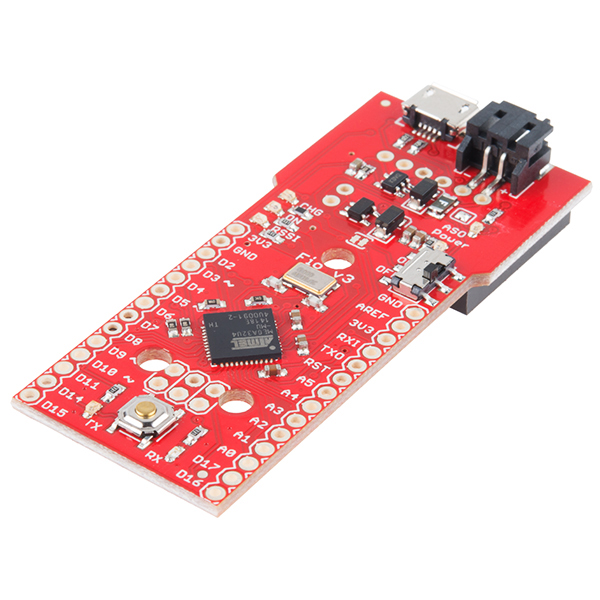
The Fio v3 is a new spin on the Arduino Fio hardware powered by the ATmega32U4.Not only is it small and LiPo-ready, it's a very capable XBee-ready development board.
The JST-connector and 3.3v system voltage make this a great development tool for portable devices, simply plug in a Li-Poly battery and you're ready to go. Wireless sensor networks and communication are made easy by the on-board XBee socket.
The ATmega32U4, running at 8MHz, makes it possible for you to use the on-board USB jack not only to charge a connected Li-Poly battery but to actually program the device! Because this board uses a similar bootloader to the one on the Pro Micro, you will need to download and install the special software driver below. There's also a board definition add-on for the Arduino IDE which will add support for this board.
We've updated this to the latest version of the 32U4 firmware, see the firmware note in the documents below!
Note: See the GitHub link below for support with the Arduino IDE.
- ATmega32U4 running at 8MHz
- Arduino-Compatible Bootloader
- XBee Socket
- Lithium Polymer Battery Compatible
- MCP73831T LiPo Charger
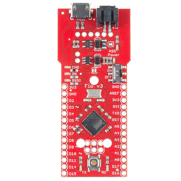
- Reset button
- On/Off Switch
- Status/Charge/RSSI LEDs
- Schematic
- Eagle Files
- Hookup Guide
- Datasheet (MCP73831T)
- Firmware Note
- Board Definition Files
- Arduino Addon Files
- Arduino Addon Files (IDE 1.5+)
- GitHub (Design Files)
Fio v3 - ATmega32U4 Product Help and Resources
Choosing an Arduino for Your Project
December 11, 2017
Examining the diverse world of Arduino boards and understanding the differences between them before choosing one for a project.
Pro Micro & Fio V3 Hookup Guide
November 8, 2013
An overview of the Atmega32U4-based Pro Micro and FioV3, how to install it, and how to use it with Arduino.
Software Reset
By connecting to the FioV3 at a baud rate of 1200 and closing the COM port, this will initiate a software reset with the Atmega32U4 just like the Arduino Leonardo (as stated in the Automatic (Software) Reset and Bootloader Initiation for a Leonardo => https://www.arduino.cc/en/Main/ArduinoBoardLeonardo ) .
Measuring Battery Voltage
The Fio V3 has the capability of measuring the battery voltage of an attached Lipo. There is a resistor divider with two 1k resistors connected to 32U4 pin PD6. PD6 is actually A11 in Arduino.
Doing an analog read on A11 will allow you to calculate the voltage remaining in the battery. The reading will be 1/2 of voltage level and you can calculate voltage with a simple equation.
Battery voltage = (analog reading * (3.3/1024)) * 2
serialEvent() and serialEventRun()
The serialEvent() function is not compatible with the Esplora, Leonardo, or Micro” that uses the Atmega32U4 https://www.arduino.cc/en/Reference/SerialEvent.
There was a customer that was able to resolve this by using the serialEventRun(). For more information, try looking through this forum that helped the customer resolve the issue => https://forum.sparkfun.com/viewtopic.php?f=14&t=41515.
Bricked Atmega32U4
Timing Issues w/ USB Communication through CDC
Interrupts Atmega32u4's built in CDC driver for USB communication can have timing issues when messing with the watchdog timer, sleep modes, and timer interrupts. I am unsure of how to fix this issue if you continue to use code that interferes with the CDC. I recommend trying a different method than using the interrupt timers.
Wrong Bootloader It's possible to brick your FioV3 if you used the wrong board selection with the wrong frequency. If you upload the wrong frequency, the IC will not be able to understand any new code that is being uploaded. It expects to have code that is compiled for another bootloader, instead of using the 8MHz frequency with the oscillator.
When either of these cases happens, the device manager is not able to recognize the device and is usually seen as an "unknown device" when the microcontroller runs the sketch. There are ways to recover the an Atmega32U4 (i.e. LilyPad Arduino USB - Atmega32U4 board, FioV3 - Atmega32U4, Pro Micro 5V/16Mhz, Pro Micro - 3.3V/8Mhz, etc) if this happens. Check below for more information:
A.) Upload when LilyPad USB with Atmega32U4/Pro Micro/FioV3 is still in Bootloader Mode
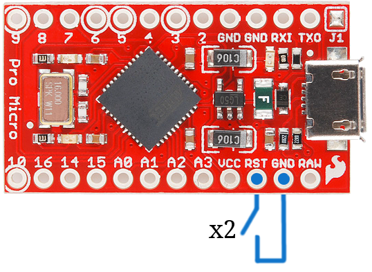
You can try the double reset method by tapping the RST pin to GND twice (since there is no reset button on the board) as explained in the Troubleshooting sections labeled as Reset to Bootloader and How to Revive a "Bricked" Pro Micro => https://learn.sparkfun.com/tutorials/pro-micro--fio-v3-hookup-guide/troubleshooting-and-faq.
1.) Open the Arduino IDE.
2.) Choose a simple code to upload on the Arduino. I used the blink test code from the hookup guide [ https://learn.sparkfun.com/tutorials/pro-micro--fio-v3-hookup-guide#example-1-blinkies ] to upload.
3.) Check your Tools>Port menu for the list of COM ports when the Arduino is connected. You will probably not see it in the list.
4.) Click somewhere else to stop viewing the list of COM ports.
5.) Ground the RST button 2x as stated in the Troubleshooting and FAQ [ https://cdn.sparkfun.com/assets/6/d/3/4/a/523c8e23757b7fbe5f8b4584.png ].
6.) Re-open the Tools>Port menu to view the list of COM ports again to see what the FioV3 enumerates to when its in its bootloader. There is an 8 second window to view the COM port when the board is in bootloader mode.
Note: Feel free to use the device manager at this step. Opening up the device manager on your operating system will help to see when the Arduino pops up and disappears.
7.) Select the COM port that the FioV3 is on before it disappears again.
8.) Hit the Upload button to compile and upload.
9.) Wait a few seconds for the Arduino IDE to compile code. The progress bar should be just over the halfway mark.
Note: On Windows, this takes about 20 seconds to compile and upload. The device will show up as "SparkFun Pro Micro (COM##)". Trying this on a Mac seemed a little faster to compile and upload.
10.) Hit the reset button twice again to place the FioV3 in bootloader mode while the Arduino IDE is uploading.
11.) If successful, you will have no error messages the Arduino IDE will tell you that it is "Done uploading."
After selecting the correct board definition and timing the double reset method correctly, I was able to upload successfully. It took me a couple of tries before I could get this right because of the timing. You should not need to go through this recovery procedure for subsequent uploads unless you brick the Atmega32U4 again.
---------------------------------------------------------------------------------------------------
B.) Outdated or Corrupt drivers
If board is showing up as Arduino Micro (COM##) or Pro Micro (COM##), try the double reset method and updating the drivers while still in bootloader mode:
1.) Use the double reset method while having the device manager open.
2.) When the board entered the bootloader mode, I right-clicked on the Arduino board in the device manager as shown in this screen shot: [ http://puu.sh/iaYYC/d45153914c.png ]
3.) I updated the driver for the board.
4.) Once the update was completed, I compiled and uploaded the code. When the uploading status bar was half-way through, I did double reset again and the problem was fixed.
---------------------------------------------------------------------------------------------------
C.) Reinstalling the Bootloader
As a last result, you can always try to reinstall the bootloader. The tutorial is designed for the Arduino Uno, but it should work for Atmega32U4's bootloaded with Arduino. The idea is the same but the specifics are different. Start by reading the tutorial => https://learn.sparkfun.com/tutorials/installing-an-arduino-bootloader. The first thing you are going to need is an AVR programmer. You can use a standard AVR programmer or any Arduino with the ISP code on it (the standard code will not work with the Leonardo). You will then need to connect it to the target device (i.e. LilyPad Arduino USB, Pro Micro, Fio V3, Makey Makey, or Leonardo) to reflash the bootloader. Don’t worry about the fuse bits or even the avrdude commands (they’re great, if you are installing third party stuff, but this will work just fine).
1.): Get a programmer
This you can do by following the directions in the tutorial.
2): Connect the programmer/Arduino as ISP to the Target Device
You will need to connect to the same pins to your target device (i.e. LilyPad Arduino - USB, Pro Micro, Fio V3, Makey Makey, or Leonardo). On the Leonardo you can connect it just like the Uno. The LilyPad Arduino - USB has small ICSP pins. I managed to solder wires directly to the pins for access. The Pro Micro does not have an ISP header and the pin numbers are different. Check the tutorial for location of the pins on the programmer. Here are the pins for the FioV3 Board:
ICSP Pins <=> Pro Micro Pin
   GND    <=>      GND
   RST    <=>      RST
   VCC    <=>      VCC
   MISO   <=>      D14
   SCK    <=>      D15
   MOSI   <=>      D16
Note: There is a silkscreen error and D17 is labeled D14 on the Pro Micro.
3.) Program Using Arduino v1.6+ go under Tools and select the correct programmer (if your programmer uses a COM port select that too), and the correct board (LilyPad Arduino - USB, Pro Micro, FioV3, Makey Makey, or Leonardo). Then select Burn Bootloader. For the Pro Micro, this will use the bootloader in the addon file, so make sure you have the correct addon file installed. You can find the latest board definitions from the SparkFun GitHub Repository [ https://github.com/sparkfun/Arduino_Boards ].
Core Skill: Soldering
This skill defines how difficult the soldering is on a particular product. It might be a couple simple solder joints, or require special reflow tools.
Skill Level: Rookie - The number of pins increases, and you will have to determine polarity of components and some of the components might be a bit trickier or close together. You might need solder wick or flux.
See all skill levels
Core Skill: Programming
If a board needs code or communicates somehow, you're going to need to know how to program or interface with it. The programming skill is all about communication and code.
Skill Level: Rookie - You will need a better fundamental understand of what code is, and how it works. You will be using beginner-level software and development tools like Arduino. You will be dealing directly with code, but numerous examples and libraries are available. Sensors or shields will communicate with serial or TTL.
See all skill levels
Core Skill: Electrical Prototyping
If it requires power, you need to know how much, what all the pins do, and how to hook it up. You may need to reference datasheets, schematics, and know the ins and outs of electronics.
Skill Level: Competent - You will be required to reference a datasheet or schematic to know how to use a component. Your knowledge of a datasheet will only require basic features like power requirements, pinouts, or communications type. Also, you may need a power supply that?s greater than 12V or more than 1A worth of current.
See all skill levels
Comments
Looking for answers to technical questions?
We welcome your comments and suggestions below. However, if you are looking for solutions to technical questions please see our Technical Assistance page.
Customer Reviews
4 out of 5
Based on 7 ratings:
2 of 2 found this helpful:
Be careful - nice but finicky
I am making a remote sensor with an XBee Pro 900 radio, and wanted 3.3V digital outputs without using level shifters. I was using the UNO, but it had 5V outputs, so I went with the Fio V3. This is definitely not as user friendly as the UNO, so I wanted to put some notes here for others and myself.
Obviously, read the hookup portion of this website. This is a different chip than the UNO, it does not use an FTDI USB connection, so you need different drivers.
As stated above, use Serial1 to talk to the XBee
With XBee Pro 900 only, you will need to remove R2 (RSSI) because it pulls this pin low making the XBee Pro 900 not work. Not an issue with other XBees (I think) but Digi decided to change around some pins for the XBee Pro 900.
The USB micro is very finicky. I found that it would re-enumerate while operating (bum-bum sound), not affecting the operation of the board, but obviously something about the communication between computer and board is not well. I also found that my computer would not recognize the device (yes, I had already installed the drivers), and I would go through a dance of resets, exiting Arduino, remove the cable to fix this. The best solution I found was that if I plugged the battery in first, and then the USB micro, the incidence of this problem decreased substantially. It also helped getting away from the "Unknown device" in Device Manager problem. I think powering up the device prior to data is necessary. A good summary of this is in https://forum.sparkfun.com/viewtopic.php?f=32&t=32342. But this leads to the next problem.
The 5V of the USB micro and the LiPo are connected together when the on-board switch is turned on, meaning the LiPo sees the 5V of the USB micro, which is bad for the LiPo. You fix this with remove of the SJ-2 jumper. This is described on this web page "http://www.forward.com.au/pfod/ArduinoProgramming/FioV3/index.html".
When it works its great because everything I need is integrated, but it doesn't "just work" like the UNO. I think bringing back the FTDI USB would make this much easier to work with. Sure, it means that this would be a little larger, but I bought this for the integration with the battery charger and the XBee, and it being a little bigger won't affect my desire for this part.
1 of 1 found this helpful:
Nice!
One little problem that Chris in Tech Support helped me solve in just a few minutes. Great tech support by the way!
The battery charge light always stays on even with the USB disconnected. The problem appears to be the boot loader is programming pin D13 as an output and leaving it that way. Pin 13 is connected to the charge LED but is designed to be an input so you can read it to determine whether the battery charger IC is charging or not.
If you put this line in your sketch setup() routine it fixes the problem.
pinMode(13,INPUT);
1 of 1 found this helpful:
Serial Communication Not Working
I can successfully upload code to the board but the Serial communication does not appear to work. I have worked with many Arduino based boards since v1 or their IDE so I am familiar with how to set the baud rate for both the board and the monitor. I tried different rates too just in case some were not supported ( for whatever reason ). Would love to know if I was just missing something.
UPDATE: Looks like this board uses Serial in a different way, so make sure to read up on Serial1 vs Serial usage as they suggested. Board works as expected using Serial1.
Thanks for your feedback. Because the ATmega32U4 has built in USB, the USB serial line is different than the hardware serial line. For the hardware serial line make sure to use Serial1. If you still have any questions feel free to email techsupport@sparkfun.com and they should be able to help you out.
5 of 5 found this helpful:
Nice board, but not for battery powered projects....
This is a nice board, easy to use and convenient to experiment with due to the USB loader.
Unfortunately, little thought was put into lowering the power consumption, so battery drain is far worse that it could/should be.
I don't feel like replacing SMT resistors, so that battery sensor alone drains the battery. Add all the bright LEDs and the board is disappointing.
I also had issues reloading the official bootloader.
Great board for working with XBee
I really like this board and I hope it keeps getting updates. I use it with an XBee radios for remote devices. I've been using the Seed LiPo Rider Pro for solar charging and it works great.
XBee Power Down issue
I can get the fio v3 to power down but the XBee leds stay lit. Can you power it down with the XBee pin 9 DTS going high???
Had to cut the charge tracer to prevent battery drain. No more battery monitoring :(
Good question. I would suggest getting in touch with our tech support team, they should be able to help you out.
Is there a way to use higher baud rates than 115200 when working with an xbee? I've been trying to jump up to 230400 but although both xbees are set up for 230400 and "Serial1" is initialized with 230400, the data received is gibberish. This doesn't happen with "Serial" though. When using the USB Serial, it can go to 230400 without a problem.
So Serial1 doesn't seem to go higher than 115200. While Serial doesn't have any problem doing so.
Is this a library issue? Maybe there's a piece of code somewhere capping the baud rate to 115200? Because the ATMega32U4 at 8 MHz should be able to handle all the way up to 1000000 baud rates. My Xbees are capable of baud rates up to 230400.
There is a voltage divider on the output battery voltage before the switch. I noticed this was a comment on the previous model as well, and I believe that means the board will always be drawing current (a bit over 1mA depending on battery level since the total resistance is only 2k!). I understand the desire to measure battery voltage, but I question putting this divider before the switch, since when the switch is off the MCU can't usefully measure the voltage. As for off-board measurement, I feel this might be better implemented with an unpopulated pad so the user can choose to add this measurement before the switch, not as the default state. Can anyone see a danger to removing these resistors/cutting the trace? That's what I plan to do to keep sleep-state current draw to a minimum.
I always desolder or cut these resistors, R6 and R7, before using a Fio v3 in a project. This reduces quiescent current to about 70µA when the power switch is off.
This mod only eliminates the ability to read the battery voltage on analog pin A10 and has no other effects.
You could also swap them for 10kΩ resistors to keep the functionality but reduce the current draw.
I have 2 fio V3 boards, current consumption is roughly 2mA when power switch is off. E.g. it is really unusable with 110mAh battery :(
With original FIO the current consumption is 0.0uA when power switch is off.
Member #401697: have you tried to cut the trace?
Sparkfun: I would like to both measure the battery when device is powered and have long battery life when not powered. I guess that it is not possible? Or can some wiring be done with board to get voltage divider after power switch?
Thanks.
The trace between pull-up resistor R14 and VBATT goes next to JP7 which is the external power switch. I think that by cutting pull-up resistor's trace between JP7 and U1 and then connecting the trace to JP7 (to hole which is closer to USB connecter) it should be possible to get both zero power consumption when Fio is switched off and battery level monitoring functionality.
As mentioned in the tutorial, the Arduino add files on do not work for Arduino V1.5. I have fixed this and put up a set of files that work with Arduino V1.5.5
These are available from http://www.forward.com.au/pfod/ArduinoProgramming/FioV3/index.html
Thanks so much for posting this! This works for me using Arduino v1.5.7beta.
It appears that the VBATT_LVL pin is not correctly marked. To monitor the voltage from the battery you will need to use A11. You can use the following formula to determine the actual input voltage.
(sampleValue * (3.3/1024)) * 2
The sample value is the value from the analogRead(A11) call
3.3/1024 obtains the number of mV/step. The DAC is 10 bit, so there are 1024 values available and the processor is operating at 3.3v.
1/2 the input voltage to the divider is sent to the pin per this wiki entry:
http://en.wikipedia.org/wiki/Voltage_divider
So in this case we multiply by 2 to reverse the division.
Thanks Logan.
I thought there was only 10 analog inputs from A0-A10. So how does analogRead(A11) work? It is working, but I never would have tried this because the A0-A10 thing.
Thanks Logan, this saved me a lot of head scratching time. :-)
to use bluetooth module you need to do Serial1.begin NOT Serial.begin this took me forever to figure out
Same holds true for the XBee (or I guess anything connected to the "integrated" radio port). Does anyone know if this is documented anywhere? I spent a long time lost because I didn't know this.
On the ATMega32U4 boards Serial is the USB port, where Serial1 is the hardware UART lines. So for anything other than USB you will want to use Serial1.
I can't stress enough how this needs to be pointed out, bolded, and highlighted. This caused me a month of debugging trying to figure out why my xbee's weren't working.
Also how do I monitor the battery status?
I plan to use a wireless charger to charge the LIPO. Is there a way to stop it from switching on while charging?
The Arduino Buying Guide says that this board can be powered from 3.3v to 12v. What pin do I wire to my 12v battery in order to power it?
Hi guys i m not english so if im speak badly so sorry for it.Im coming subject.I have fio v3 and 6 v nimh battery.Can i run it with from JST connector?
Anyone know how to reprogram these remotely using Series 2 XBee? Seen a few people say it's possible, but I can't find any examples anywhere. Any help would be appreciated.
There is a very large solder bridge between the VCC pin and the D- pin on the USB connector on one of my newly arrived Fio boards. Might want to check on quality control.
Hello. Please explain exactly where is the jumper SJ2 to be cut to this damn Fio ceased to kill the batteries from overcharging. Is the jumper near ASO LED?
Can someone update the eagles files of this product on github so they match the files posted here?
The files on GitHub were actually the correct ones. You'll find that everything has been updated to the most recent version. Thanks for the heads up! :)
Sorry if this is a repost, it didn't appear the first time.
It seem that I brick two FIos v3 only by programming them via USB. It happened to me on two occasion with two different sketch on two different computer. Once the sketch is uploaded, the Fio doesn't excute anything and it never appear to mount via USB. The first time I blame the USB connector but now it seem to be more MCU related. Beside flashing the booloader via ISCP, is there something else I could try?
Make sure you have the drivers installed correctly and are using the correct board definition in the Arduino IDE. Also keep in mind there are a few differences in the ATMega32U4 vs the ATMega328, so it might be working just not the way you want it to (one very common thing people run into is that the hardware serial line/ XBee port is on Serial1 not Serial). If you are still having problems email techsupport@sparkfun.com
Hi, I have two Fios v3 that stop mounting USB once I programmed ( flash ) them ( two different program ). It doesn't seem to be the software since uploading them on another board ( Fio ) works fine. It happened on two diffrent computers. It looks like uploading a sketch bricked them since nothing works ( not just USB). Is it something specific to the 32u4 because I never experience something like this on any other arduino board? Beside using ISCP to reflash the MCU, is there something else I could try tro revive those boards?
I love this little board and have used several of them. The only problem I have had is with the micro-USB connector. Its physical connection to the board is just too fragile. I have now had three of them rip off which pretty well ruins the board. This is a particular problem when the fit with the male USB connector seems a little tighter than normal. This has caused me grief with the Sparkfun Cerberus cable. It sure would be great if future versions of the board had a stronger physical connection for the USB. Thanks much.
A 3D Model of this board would be so helpful. The hole locations, connector locations, reset switch and clearance for the XBee board make this board non-trivial to mount/enclose. I tend to use this board for nearly all my projects and I model all my projects in Autodesk Inventor before I build. Consider this a friendly request for a 3D Model.
I have one done in Solidworks.
I dont think it has all the holes but you are welcome to a copy.
Shouldn't this be called the Fio Pro? And where is V2?
Nope, Pro is the name we use for a slightly stripped down version missing headers and other connectors (like the Arduino Pro, Arduino Pro Mini, Pro Micro and the Mega Pro). This is a new Fio with a different microcontroller. As for the V2, it is right here.
I don't know if this is anything, but I have been going through the schematics to find where VBATT and USB_VCC get connected when the power switch is turned on. There is a net named RAW on the wire just after the power switch connecting to U6. I cannot find any other instance of RAW on the schematic. Is it possible that the RAW net is connected to USB_VCC? When running of of USB, do you need to turn on the power switch to make the board run? (RAW is after the power switch and would connect to VBATT when the switch is closed). If that's true, then there is a trace conecting from the USB_VCC after S2 going to U6 that needs to be cut. At any rate, somehow USB_VCC connects to VBATT when S2 is closed. The switch connection to U6 needs to be traced back to USB conector pin 1. I'm a litle suspicious of the label CHARGE_STAT. It connects pin 1 of U6 back to PC7 on the Atmega. It's possible that charging status LED D4 is always on if pin PC7 is sinking current. The datasheet talks about the LED resistor connection, or connection to a micro pin using a pullup. They don't talk about connecting both at the same time. Also, there is a labeled wire all by itself on the schematic labeled "CHARGE_STAT" just above the voltage divider. It doesn't seem to be connected to anything. It seems strange. Just wondering if that might be causing problems in the netlist. Sorry for the long post. I have been looking at alot of schematics, checking net lists and reading too many datasheets lately...
Why not just up the resistance on R14 and R15? I've routinely used voltage dividers using 100kohm resistors with other micros. The trick is to bypass R15 with a 0.1 uF capacitor (or maybe 0.01uF) after they are replaced. It's hard to tell from the pictures but they look to be 0805 or possibly 0603 package. Removal is fairly simple. One of my favorite tools, (actually it should be upgraded to my favorite tool) is "Chipquick". It is a very low temp solder that is excellent for removing SMD components. You just melt it onto the SMD solder joints where it mixes with the existing solder to lower its melt temp. Once that is done, all of the solder joints remain liquified long enough to remove the offending component. Then, touch up with flux and desolder braid. After that, pop on the new resistors. That should drop the current consumption to 20 uA. Still not perfect, but a nice improvement.
This design has some serious problems. If a battery is connected with USB connected and the power switch is on then 5 volts is connected to the battery. BAD! The charging LED is always on. BAD! All the LEDS for power, serial in and out are always on, not good for battery power. BAD!
Yes I agree see my comments on the problems with this board and what you can do about them http://www.forward.com.au/pfod/ArduinoProgramming/FioV3/index.html
I may have found a very strange bug: printing the result of modding a large number (over 10,000,000) with 1000 concatenated with a string seems to crash the microcontroller. If the number is concatenated with a char, no problem. I don't see this error on a Leonardo, which also uses the 32u4, so it may be a problem with the board definition for the Fio v3. This one was pretty annoying for me, so I hope this helps someone in a similar situation! Here is the code I use to replicate the bug:
My CHG (charge) light is always on, even while running under battery only and when there is no battery. I thought the purpose of the light was to indicate that the battery is being charged. If not, how does it differ from the power light.
FYI: I am not using pin 13
can this fio identify as a different usb device? id like one to show up as a midi device.
Is it possible to use PS dualshock 3 battery for arduino fio v3 ?
Great board with some simple but extremely convenient differences from the original Fio. Even if you don't use XBee this is a great board for sensor networks.
I just question the decision to use a micro-B connector, especially when it's the programming interface. Extremely fragile. They will break at some point.
I have two XBees, each on Fio v3. I've checked over 10 times that I'm using CoolTerm that I've written the correct DL for each. For some reason, when I power up both boards, neither ASO light blinks. Any ideas as to what's going on?
I figured it out - I had to flash the firmware on both again and make sure that one was configured as Coordinator and one was configured as Router. Now they connect and talk!
Can I use CoolTerm directly with this board, or do I have to use something like the Explorer?
For a basic serial connection? You could use CoolTerm, TeraTerm, Hyperterminal...whatever your terminal of choice is.
I couldn't get CoolTerm to work directly with the board. I ended up using the USB Explorer...
Sorry this is a bit late, but other people may have the same question as well. You can use CoolTerm to talk to the board over the ATMega32U4s USB port. But that USB port does not connect to the XBee slot. You can write a sketch that will read the XBee port and write to the USB port and vice versa, but if you are trying to configure the XBee you will most likely want the XBee Explorer.
Can I use a 3.7v 500mAh Li-Poly battery with this?
Sure.
I have just started with the Fio v3.
I managed to load the Blink example into the board from my Mac but it now seems to "lose" the serial port. I think I could have loaded Blinky with the board set as a Fio not a Fio v3 (Sparkfun library).
I can get the connection back briefly by doing a quick double reset, connecting and uploading but this seems very wrong.
The serial monitor wont work while a program is running.
I read on the site that I might have to reinstall the Bootloader for which I need yet another connector (sigh)
Has anyone else had this happen- am I on the right track with the Bootloader?
Many thanks
What's the pin spacing if I want to solder female headers for jumper cables and breadboards?
What is the purpose of the built in jumper between USB_VCC and RAW? If you plug in a battery, then turn the power switch to on, then plug in a USB cable, 5 volts is dumped onto the battery through F1. My Lipo got to 4.5 volts and started to get warm before I noticed this.
Yes there are a number of design flaws with FIO V3, see http://www.forward.com.au/pfod/ArduinoProgramming/FioV3/index.html for details. I am currently writing up a project that overcomes most of these, cutting tracks + extra components
is there any way to turn off all the LEDs on this board? its not so much about power consumption (though i imagine they do consume a measurable amount) its more about LIGHT - i am using this on a breath sensor used in sleep apnea studies and this thing generates so much light that I have had to cover each LED with blu-tack but its hardly professional looking.
Have got two Fio v3 and both are detected by Windows as VID_1B4F&PID_0004 The drivers referenced here does not support this PID.
Could anybody help to find correct drivers?
Device does not work with Windows 7x64. Drivers are not compatible with Win7 & XP and installable as "legasy software" only.
OK, for people having issues with this board running on Windows 7 (and maybe other OS's), here is the problem I was encountering:
When downloading the IDE restarts the board and it goes into bootloader mode. It only spends 8 seconds in bootloader mode before going back to the user program, which wasn't long enough to force Windows to update the driver. The device would disappear before I got far enough to select the driver.
Step 1: Open the .SparkFun ProMicro.inf file in an editor. Add the following two lines to the DeviceList and 64 bit DeviceList:
%DESCRIPTION%=DriverInstall, USB\VID_1B4F&PID_F100
%DESCRIPTION%=DriverInstall, USB\VID_1B4F&PID_F100&MI_00
Step 2: Save the file, open a command prompt (as administrator) and type: set devmgr_show_nonpresent_devices=1
start devmgmt.msc
Step 3: In the View menu, show Hidden Devices. Find the USB IO Device, right click and update driver. Select to open a driver on your computer, then select to browse for a device. Select the driver from Step 1.
Now your device should enumerate and program correctly. Took me a full day of screwing around with it to get this right, SparkFun, please add the device id's to your GIT download.
Hi, New to the proMicro and this forum. Followed all this but I'm still having no success uploading even the blinkies" example.
I'm running XP Home, on an Atom based Acer netbook. The drivers for both the main port (COM16 in my case) and bootloader port (COM17) have been successfully loaded and the correct Addon has been installed as per Sparkfun's instructions and Arduino forum posts on this problem. (I'm running V1.0.5 IDE with the Addon dated 24/1/2012) I'm using the recommended double reset press to get 8 seconds of bootloader port access. I'm using XP's Device manager to see that the ports are switching correctly. They are (I'd estimate that COM17 is on for about 8 seconds)
However, I'm finding it impossible to time the port changeover so that I can get the sketch uploaded:
I usually time it too late & get a prompt to choose another port because port 17 doesn't exist any more. If I leave it a little longer, the IDE reports a problem opening the port. If the upload does start, I get "avrdude stk500_getsync(): not in sync resp=0x3f", which I assume means that the flash contents do not equal the program being uploaded.
I've tried using your suggestions and updated the drivers to those on the Sparkfun site. Still no joy. Have I missed a step somewhere? Any help would be much appreciated.
Update on my last comment: Still no joy with Windows but very easy with the Linux version.
Running Ubuntu 12.04 Using the standard package install doesn't work, as this installs Arduino V1.0, which doesn't recognise the PIDs for the ProMicro. However, downloading and unpacking the V1.05 gzip file to my home folder works fine. Put the Promicro specific hardware files into a hardware subfolder of the sketchbook folder and then just run Arduino from it's current location. Compiles faster and doesn't seem to need a reset to access the bootloader.
Anyone want precise details of the steps I took, please post a reply.
I used the Fio with an XBee and motor driver chip to quickly prototype a small robot. More details here: http://mechinations.wordpress.com/2013/11/10/robot-prototyping-101/
Are the Status/Charge/RSSI led's different colors? I ask as I'm probably going to light pipe them, and might use just one to cover all three if so.
Has any one successfully uploaded a sketch witlessly over xbee? If so a bit o help would be appreciated, all I get is: "avrdude: error: buffered memory access not supported. Maybe it isn't a butterfly/AVR109 but a AVR910 device?"
i can upload over usb but i would like to do it wireless.
You can not do wireless sketch uploading with these boards (well not without writing a custom bootloader). The XBees connect to the hardware serial port, but the code is uploaded over the USB port. Because those ports are different and the bootloader is looking for code on the USB line and not the serial line you can not upload code wirelessly to these boards.
I am fairly new to Arduino development, however I have been able to upload sketches to an Uno and a Micro. Unfortunately I cannot figure out how to upload to the Fio. I keep getting the following error message:
if I press the shift button while initiating upload I get: avrdude: usbdev_open(): did not find any USB device "usb"
I have Arduino IDE 1.0.5 running on Windows Vista. I have searched the web and tried a ton of things. I have the right board selected ("Arduino Fio") and I am definitely using the correct serial port.
Any ideas?
Problem solved by Sparkfun tech support!
I had to select "Sparkfun Fio V3 3.3V/8MHz"
Doh!
Warning!! DO NOT run the standard BLINK example if you have a battery connected to this board. The output of pin 13 is connected to the output of the battery charger chip STAT and THERE IS NO CURRENT LIMITING RESISTOR.
Excessive, damaging, current will flow when one output is high and the other low.
Standard Arduino boards add a current limiting resistor between the two output pins when this situation can occur, such as with the RX serial pin.
I am unable to load the "blink" example on my fio v3. There is no error message, but no blinking though! Is fio v3 compatible with ide 1.0.3? What about Due?
Also, make sure you are trying to blink the right LED. The standard Arduino blink sketch is on pin 13, but on this board there is no LED on pin 13 (its actually connected to the battery)
The Due is only supported in IDE 1.5. As far as the Fio goes, if you aren't getting any error messages, make sure you are selecting the correct board, as well as well the right pin in your code. Also make sure you've added in the board support files for the Fio (check the links above). If you are still having trouble after double checking these, please email techsupport@sparkfun.com. They'll be able to assist you further than we can in the comments.
I have put up a tutorial on setting up the RN-42XV bluetooth module and the RN-XV wifi module with this board at http://www.forward.com.au/pfod/ArduinoProgramming/FioV3/index.html
I have an XBee radio that, when plugged into an explorer, is fully functioning. However, when I plug that XBee into my FIO v3, Serial1.available() always evaluates to false. On the FIO v3 I've also soldered an accelerometer in on the GND, 3V3, A1, A2, A3 pins and am able to read those values just fine via analogRead(). Another oddity I noticed is that even when I don't do a Serial.begin() the Serial.println() commands I was using for debugging are still showing up in the IDE's Serial Monitor when the FIO is connected to my machine via USB. Any ideas welcome on where I could be going wrong!
I discovered by slowing down the Serial1.begin from 115200 (a speed suggested by the XIG example) to 9600 that Serial1 is working fine for XBee communication =)
Unfortunately to fit my enclosure I have to remove JST connector, is it easy to desolder it ?
Looks like it's a surface mount connector - shouldn't be any hassle at all if you can heat up both pins at the same time or just put a bit of force on one side while heating that pin until it lifts clear, then do the other side.
I'm installing the Fiov3 Addon to Arduino IDE 1.5.2. My sketchbook location is /Users/myName/Documents/Arduino. After I extract the zip, should the path be /Users/myName/Documents/Arduino/hardware/Fiov3/boards.txt or should it be /Users/myName/Documents/Arduino/hardware/boards.txt? I tried both but don't have Fio v3 appearing in the Tools->Boards menu. TIA!
Switching to Arduino IDE 1.0.4 did the trick with install path of /Users/myName/Documents/Arduino/hardware/Fiov3/boards.txt ... would be nice to have the add on working in the latest IDE but I'm good for now, thanks to Ragnorok/BJfreeman/TechIsCool in #arduino on freenode!
I have bought a few Fio v3's from Sparkfun now and wanted to interface it with an SD card and the Roving Network's Wifi card so that I would have a fully portable web server.
I notice that D12 and D13 aren't pinned out and those are the SPI data lines I need to talk to an SD card with Lady Ada's breakout (http://www.adafruit.com/products/254).
Any way to talk SPI off of the Fio v3? Are they exposed somewhere in the X-Bee socket?
Dave
Hi, Dave. Yes, the SPI port is brought to the pins D15, D16, D17, which are "virtual" on other Arduini but at the bottom of the two rows of headers on the Fiov3. Used them to talk to a CC1101.
I'm having great difficulties uploading a simple sketch to the Fio v3 and am getting conflicting advice which version of the IDE to use. I think I've now tried every conceivable combination of IDE, Addon etc but still have no luck. The best results seem to be with IDE 1.0.3 and the Addon installed in a directory called "hardware" in the directory of the Sketch, then selecting "Arduino Fio v3 (Leonardo)" from the Board menu. That allows me to compile the sketch without errors and start what seems an upload (observing a few blinks of the RX LED). The upload however hangs and the sketch does not start to run. I've tried pressing the reset button once and twice at various moments (before initiating the upload and after). I now have two boards, one where the ASO LED is blinking (about 3-4 times per second) and another where that is not the case.
I've spend many hours on this now and I'm getting a bit annoyed (as you probably can imagine). Is it really that complicated to program a very simple sketch (the famous LED blink sketch) into an Arduino Fio v3?
I'm using a linux workstation; the USB serial port is always recognised without fail after inserting the USB cable.
Any advice is much appreciated.
You can find interesting explanation on this page http://cholla.mmto.org/computers/arduino/promicro.html, even if it is for the pro-micro, this is the same behavior for FIOV3. I have recently bought one, running under linux also, i use eclipse + avrdude or Arduino IDE as well to program it. I have now a little experience on this board an i can try to help you if you want. For example on Fedora the modem-manager http://forums.fedoraforum.org/showthread.php?t=252054 was disturbing the soft reboot (The "trick" of setting the baud rate to 1200 and then opening and closing a connection ). The better for going on is that you open a topic on the https://forum.sparkfun.com
For some reason the IDE changed the selected board to Arduino Fio instead Fio v3 (Leonardo) when I was uploading code. Now it doesn't work, it still upload code but doesn't work correctly, plus TX/RX leds doesn't blink in the process... Any solution??
Trying to simply get a WiFly to work with this Fio (V3). It would seem simple serial communications should not be that difficult. I'm evidently making this too hard or missing something fundamental. Here's my simple sketch just to get it to join my network. Any feedback on what I'm doing wrong?
void setup() { Serial.begin(9600); delay(500); Serial.print("$$$"); delay(100); Serial.println("set wlan ssid thisismywlan"); delay(100); Serial.println("set wlan pass thisismypassword"); delay(100); Serial.println("save"); Serial.println("reboot"); }
void loop() {
}
So...it turns out there really is no problem with these two playing well together if you realize: 1) The XBee socket is accessed via Serial1, not Serial. I had tested this proposition earlier, but was fooled by the second issue. Also, it's not documented anywhere I can find above in the product description - something I've suggested Sparkfun may want to consider. Based upon reviewing these comments as well as the ones in the forum, lots of folks have stumbled on this issue when trying to talk to Xbee socket devices of various flavors. 2) When putting the WiFly RN-XV into command mode, provide sufficient time for the commands to execute and respond. Once I allowed 1 second to elapse after each sent command before reading any output from the WiFly device, I was in great shape.
I hope this feedback helps someone else facing the same apparent dilemma.
On a final note, Sparkfun Tech Support was very helpful in working through the issue with me via email. My thanks in particular to Michelle who even took time to mock up what I was attempting and came to the same conclusion, coincidentally at just about the same time.
From a quick look at the schematic, it appears that the XBee socket (WiFly) is on the second serial port not the USB port. I recall reading that there is support for the second serial port by calling Serial1.begin and Serial1.print (note the subtle numeral 1 at the end of "Serial"). I might not be remembering this right, that is, I might have the ports reversed. Double check the documents before changing your sketch. If it's not in the documents for this product, take a look at the docs for the Pro Micro (DEV-11098) they use the same microcontroller. In particular look at the "Getting Started Tutorial".
Hi,
I recently bought an Arduino Fio v3 and XBee Series 1 I'm trying to establish 2-way serial communication between the Fio/XBee and another XBee connected to USB Explorer and my MacBookPro.
However so far I'm only able to establish 1-way communication. Meaning I can send commands e.g. 1, 0 to the Fio/XBee and make it switch on/off the onboard LED. However I'm unable to receive any communication back from the Fio/XBee.
TX LED on Fio is always on RX LED on Fio is always off. ASO LED is blinking indicating established connection. RSSI LED lights up when sending commands to the Fio/XBee.
I connected the XBee to another Arduino UNO with regular XBee shield and 2-way communication is possible without any problem. Which made me exclude any setup error on the XBee side.
I configured serial communication on the Fio/Xbee to use Serial1 (which supposedly sends it directly to XBee vs USB). If I use Serial it sends communication back to my Mac via the USB cable which crashes my Mac after a short period of time. Fio is currently powered by either USB to my Mac or external USB power supply.
Any advice would be appreciated.
Best, Daniel
I'm using fio v3's and xbee series 1. I've got many of them scattered around transmitting environmental data and gps. I'm listening to the xbee comms with an xbee and xbee explorer connected to a beaglebone and one on my Mac. I have no problems with comms other than when I use xbee and USB comms at the same time. For example if I write to Serial1 while plugged into USB on my Mac I can actually reliably crash my Mac. Yup, serial driver panics and takes out the kernel. I don't transmit the other way yet though.
Hi Daniel, i am facing exactly same problem as you, only one way communication possible between FioV3/Xbee S1 and UNO/xbee . Unable to send from FIOv3 , RX led always off and ASO led blinking. i am running under linux and i can get data on Serial port. Do you have solved your problem ?
Any idea why using pins D2 and D3 for software serial rx/tx would work just fine on the UNO but aren't working on this v3 Fio? I'm trying to get the Fio to talk to the Atlas pH board. It works fine on the UNO but the pH board doesn't respond to any commands like the UNO does.
Yeah, I don't think 2&3 are software change interrupt pins on the fiov3. I'm using D9 for rx from a GPS and it's working for me at 4800 baud.
Has anybody had any luck installing the new drivers/updates on Mac OSX? I put the folder in the sketchbook folder per the readme.txt file but don't see the new FIO (leonardo) version in the board list. Any suggestions? Thanks.
turns out you have to dig deeper into the folder system and find the similar folders under the application. Add/replace the current folders into those existing ones. Also, had to append the text from the boards.txt file to the original.
Love the board. Worked perfect for an art project. This is a really great solution, particularly because of the ability to generate USB keyboard and mouse events. It would be nice to be able to use all 12 analog inputs. One is dedicated to the battery level monitoring. It would also be nice to have examples of using 2 of these and 2 x-bees for the first timers. A simple USB Serial to X-Bee echo program would be useful.
I see more pins on this Fio v3 than on the Arduino Fio. I can't find a definition of which pins are capable of PWM. Can someone help with that please? TIA.
PWM ports on the Fio v3 are marked with a ~ next to the pin number. They are pins D3&D5 on Timer0, pins D6&D9 on Timer1, and pins D10&D11 on Timer2. I have also been looking for a pin and port map of the Fio v3 without any luck. I am in the process of making my own and will post it when complete. I am using pins D9, D10, & D11 to drive 3 DC motors. I chose those pins since I could change the timer settings without interfering with the Timer0 which is used for things like the millis() function and the delay() function.
Thanks. I'm using some sample code from PulseSensor.com and it uses an Interrupt, Timer2, but they're saying it disables PWM on pins 3 and 11.
I'm considering using the TLC5940 to get 2 functioning sets of PWMs for 2 RGB strings.
The question becomes what I can do with code that uses Timer2 and can still talk to the TLC5940 on alternate pins other than 3 and 11.
The schematic shows that there is a resistor dividor circuit to monitor the battery voltage from what looks like Analog pin 10. Is this correct, do i just need to set an analog read of pin 10 (which i assume will read that pin 10 not the normal digital 10) to read this voltage?
Did you change any of the contents of the "Arduino Addon and Driver Files" recently (last week)? Magically, I can't upload anymore code to my board. It fails with the same error that's been described when the ProMicro addon stuff was broken (http://arduino.cc/forum/index.php?topic=111213.0). This happens on Windows as well as on Linux.
It's been already working however, so I would exclude the bootloader version as a reason.
I can't track it back to a change in the addon files (no backup of old stuff here). Yet I'm pretty sure I've seen that pins_arduino.h in the prior version had an error in the SPI mapping. The moment I did a fresh Arduino IDE (1.0.3) and addon code install (yesterday) matches pretty much the point where it stopped working.
I was able to upload once to this board, but now it won't even show up as a serial port. What do I do? I think may have used the Arduino Leonardo as the board type instead of the Sparkfun version. Is there a way to recover from this?
This exact same problem happened to me, I selected the wrong board and it successfully and it would detect it anymore. The way I fixed it was I used Ubunutu and managed to upload code on it again.
I am having trouble getting this to work with XBee XSC S3B on peer-to-peer (transparent mode). The x-power is set to lowest and loopback test with x-ctu showing the chips to be in working order. Any ideas on what might be wrong?
Would you clarify "Fio v3 is not yet compatible with the Arduino v1.0 IDE" I've been using the original Fio with the Arduino IDE and have not had trouble. Is this incompatibility new to this version of the Fio?
It is because it uses the ATmega32U4 which has usb support built-in. This is not supported as yet but will be in the future. It really is no big deal.
NEW FIO! Been waiting for this.