- Home
- Product Categories
- Development Tools
- Gadgeteer - Relay ISOx16 Module

Gadgeteer - Relay ISOx16 Module
Replacement: None. We are no longer carrying this product in our catalog. This page is for reference only.
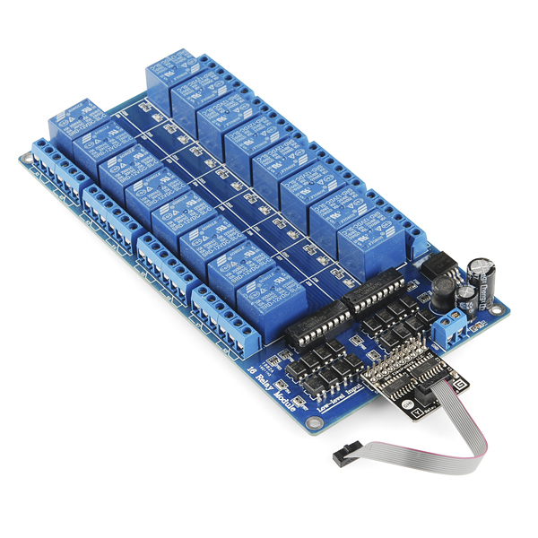
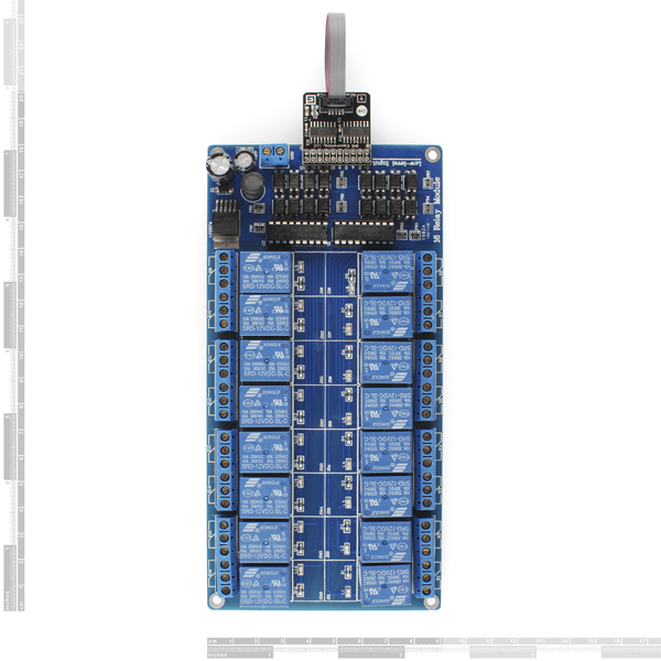
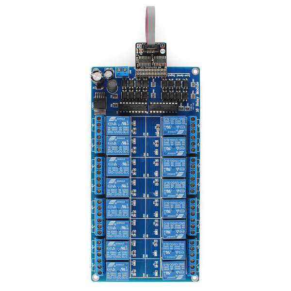
It's hard not to get excited about this many relays, especially when they're optically-isolated and individually controllable. All 16 relays are rated up to 250VAC or 30VDC and 10A, so you could do some serious (or not so serious) home or lighting automation! And if this isn't enough relays for you, multiples of this board can be added to any mainboard! Screw terminals allow for secure connection to each of the relay lines.
Microsoft .NET Gadgeteer is an open-source toolkit for building small electronic devices using the .NET Micro Framework and Visual Studio/Visual C# Express. This module is designed to quickly and easily integrate into any .NET Gadgeteer project.
- Relay ISOx16 Module
- Gadgeteer Cable
- 198mm x 90mm
Comments
Looking for answers to technical questions?
We welcome your comments and suggestions below. However, if you are looking for solutions to technical questions please see our Technical Assistance page.
Customer Reviews
No reviews yet.
I got this device running on a arduino breadboard clone running a Mega1284P chip. I am using the code from here bildr. You have to modify the clearRegisters to set all of the 74HC595 pins High so the relays are off. Then to turn on the relay set the output to LOW.
I ordered the connector that was in the "Customers also purchased" section(PRT-08506) for this with out looking at the specs, it is wrong my fault Digikey I guess.
SO I have some twisted pair wire jambed in the end of the provided cable for the time being. Here is what I came up with for pins on the cable.
I have pin3 to GND, Pin 4 to 5v, Pin5(RCLK) to D9 , Pin7(SER) to D8 , Pin9(SRCLK) to D10, and finally pin10 to GND.
Hope this will help someone else.
Glenn
What is the purpose of optically isolating a mechanical relay?
As with what bdcannon said, this means that your controller is never electrically connected to mains power, meaning that your controller is safe from being fried, and also that you are safe from being fried if you are playing with other parts of your project. It also helps prevent accidentally burning out a port on the MCU because you tried to sink/source too much current to the MCU. Definitely a big plus here. It also helps keep noise from the relays switching on and off from affecting other systems (assuming you have two supplies, one for the relays one for the rest of the system, which isn't a bad idea if you're going to do lots of fast switching).
Relays already provide galvanic isolation, so adding an optocoupler between a relay coil and an MCU is redundant in that respect--that's what I suspect tristan was getting at. There are cheaper, more compact ways of dealing with the other issues you mention, especially on an integrated PCB like this.
In this case, it looks like they've got a couple shift registers on that little black interface board driving optocouplers which in turn drive some transistor arrays that finally drive the relay coils. That should give you the ability to run several of these boards from mutually isolated DC (coil drive) supplies, which I guess could be handy in a few cases, but I'm having a hard time thinking of any.
Optically isolating your controls (like your nice MCU or raspberry pi) will protect it from surges by not actually having a conductor between the two. Let's say if you using this for your christmas lights and your christmas lights, god forbids, gets struck by lighting or something not so crazy, your controls will be safe, electrically isolated.
I can not tell you how helpful this is. I used to use Grayhill relay boards for all of my industrial automation, which was an upwards of $250 per board. Simply outrageous. Thanks for supplying this at such a low cost.
For those that were looking for the data sheet on this: http://www.ghielectronics.com/downloads/schematic/Relay_ISOx16_Module_SCH.pdf If the site doesn't work just click on the Tutorial link on this item and look for it under the "Resources" tab.
How hard would it be to wire this up to a pi or and arduino. Building a car computer and this would be great for trigger lock and lights, but I have a strong hatred for .NET. I image if you figure the pinout you could wire it up. Its all electricity :D
Looks like a great product! I would like to use this with an Arduino. Is there a schematic available?
The web links provided contain virtually no specific information, but digging through the general information on the Gadgeteer site, it seems that this uses a "Type Y" socket, which seems to be general GPIO. So I'm assuming it uses some sort of shift register arrangement?
Any extra info would be great.
This might suit your needs better: http://www.amazon.com/gp/product/B0057OC66U/
There are solid state versions and 5V versions as well. It would be cool if SparkFun carried something like this.
I can't make out the relay part number from the photos. Are they SPST, DPST or DPDT, or other? Kinda important. The Gadgeteer page doesn't say.
Great! Thanks for the help!
The company that makes the relay is Songle. (Part# SRD-12VDC-SC-L) I couldn't find a good data sheet but I found this company http://tinyurl.com/cudo36b which sells products with the same relay and they have a schematic showing that it is SPDT.
I would assume SPDT since each relay has 3 terminals (no, nc, common)
As there are three contacts per relay, I would expect it to be SPDT. But we'll check on that for you.