- Home
- Product Categories
- DC/Gearmotor Driver
- SparkFun RedBot Mainboard

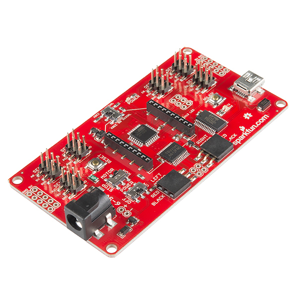
SparkFun RedBot Mainboard
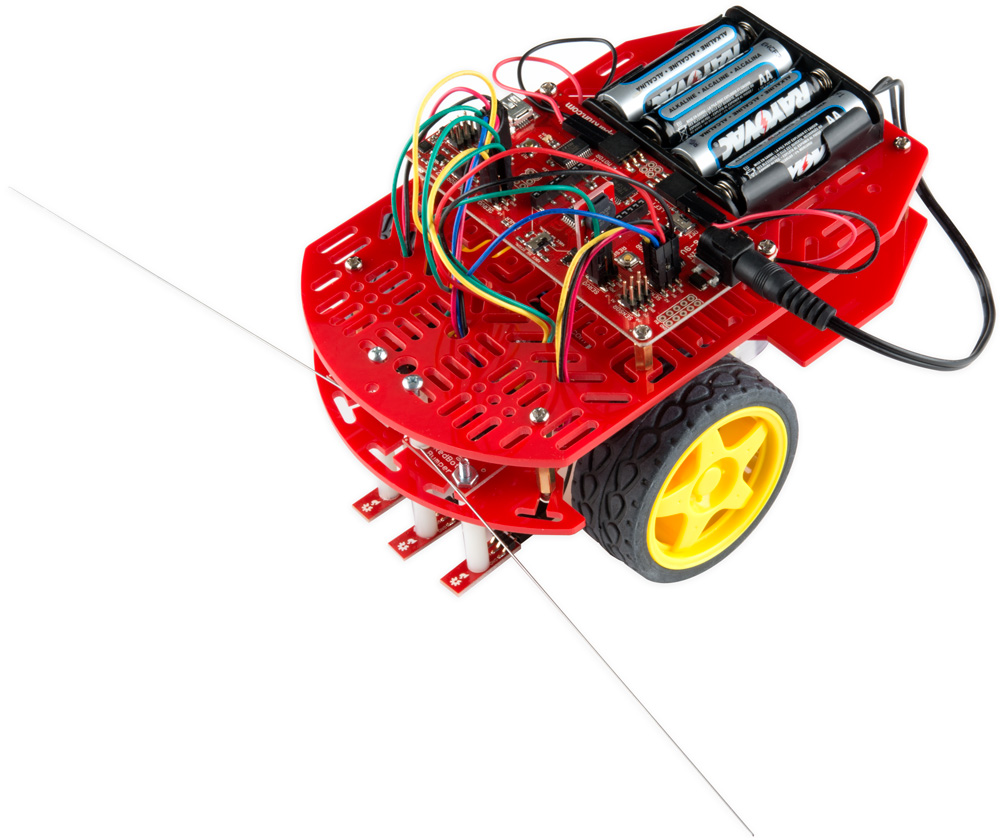
The SparkFun RedBot Mainboard is a robotic development platform that works with the Arduino IDE. The RedBot is a motor driver and Ardiuno combination with various headers and connections, eliminating the need to stack multiple shields. By using the RedBot accessory boards and your own chassis, you can design a robot to suit your needs.
The RedBot comes pre-programmed with the Optiboot (Uno) bootloader. By simply connecting a USB mini-B cable, you can program it in the Arduino IDE using our example code, or your own. The optional add-on sensors attach to the main board via 6-pin headers or jumper cables to increase capabilities.
Check out the entire RedBot family of products!
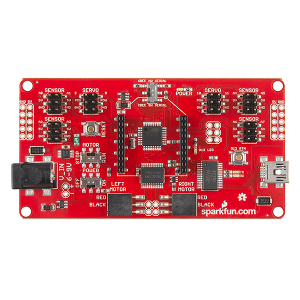
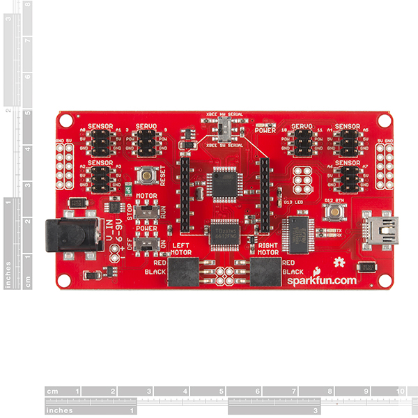
- 5V Logic
- 6-9V Input Voltage via Barrel Jack or 2-Pin Header
- ATmega328P (pre-programmed)
- TB6612FNG Dual DC Motor Driver
- USB Programmable via FTDI
- XBee Port with HW/SW Serial Switch
- 2x 3-Pin Female Motor Port
- 2x 6-Pin Male Optional Servo Header
- 4x 6-Pin Male Optional Sensor Header
- Schematic
- Eagle Files
- RedBot Experiment Guide
- RedBot Shadow Chassis Assembly Guide
- Datasheet (ATmega328P)
- Datasheet (TB6612FNG)
- Datasheet (FT232R)
- GitHub (Design Files & Example Code)
- GitHub (Library)
SparkFun RedBot Mainboard Product Help and Resources
Wireless RC Robot with Arduino and XBees
March 12, 2019
In this tutorial, we will expand on the SIK for RedBot to control the robot wirelessly with XBee radios! We'll explore a different microcontroller and wirelessly control the RedBot at a distance.
SparkFun Line Follower Array Hookup Guide
October 15, 2015
Learn how to connect the RedBot Line-Following Sensor Bar to an Arduino-type microcontroller. Use the example sketches to read data from the bar, and try out a simple line-following algorithm.
Actobotics Basic Differential Platform
December 22, 2014
Get started with Actobotics with this simple vehicle. Then expand and customize it for your own evil robot empire.
Wireless Gesture Controlled Robot
April 25, 2019
Control the RedBot wirelessly based on the movement of your hand using an accelerometer, Arduino, and XBees!
Choosing an Arduino for Your Project
December 11, 2017
Examining the diverse world of Arduino boards and understanding the differences between them before choosing one for a project.
Upload Error
If you see the below error code when uploading to the Redbot Mainboard you may want to double check your power switch.
avrdude: stk500_recv(): programmer is not responding
avrdude: stk500_getsync() attempt 1 of 10: not in sync: resp=0x98
Core Skill: Robotics
This skill concerns mechanical and robotics knowledge. You may need to know how mechanical parts interact, how motors work, or how to use motor drivers and controllers.
Skill Level: Rookie - You will be required to know some basics about motors, basic motor drivers and how simple robotic motion can be accomplished.
See all skill levels
Core Skill: Programming
If a board needs code or communicates somehow, you're going to need to know how to program or interface with it. The programming skill is all about communication and code.
Skill Level: Rookie - You will need a better fundamental understand of what code is, and how it works. You will be using beginner-level software and development tools like Arduino. You will be dealing directly with code, but numerous examples and libraries are available. Sensors or shields will communicate with serial or TTL.
See all skill levels
Core Skill: Electrical Prototyping
If it requires power, you need to know how much, what all the pins do, and how to hook it up. You may need to reference datasheets, schematics, and know the ins and outs of electronics.
Skill Level: Noob - You don't need to reference a datasheet, but you will need to know basic power requirements.
See all skill levels
Comments
Looking for answers to technical questions?
We welcome your comments and suggestions below. However, if you are looking for solutions to technical questions please see our Technical Assistance page.
Customer Reviews
4.6 out of 5
Based on 5 ratings:
1 of 1 found this helpful:
Great for a small XBee-controlled robot.
The board does it's job well if you're looking to build a small wireless robot. As a bonus it seems to run fine on 5V from a USB battery pack. 4 stars because there are minor issues with the silk screen labelling and associated Arduino library.
Delightful Robot Mainboard!
The SparkFun RedBot Mainboard is a wonderful blend of Arduino Clone and Motor Driver. The convenience of an onboard Dual Motor Driver makes development of small differential drive Robots simple and clean. I desperately like that the last two Analog pins from the ATmega328P are available for use along with an integrated user Button. Furthermore, 3-Pin Male Servo Style Headers are used at each IO. Building small Robots just got much easier!
The board is really very useful.
With lots of resources specific for robots development the boad help us to save lot of time,
BEST customer service and products ever!
Out of nowhere and much to my shock and surprise, a brand new, FREE, not-even-requested board arrives to replace the one I had purchased a very long time ago. Any other company almost certainly would have said "That's on you, buddy!", much like I said. Actually, I literally said "this one's on me" and was completely fine with it because I know SparkFun has quality stuff and I've always been satisfied and happy and know this was probably a one-off. I'm no expert (yet), but I've purchased other boards and project items from other places, and I've yet to find any other company that cares this much about quality and customer satisfaction.
Thanks guys, you rock!
Original Review: I bought this a very long time ago, then got side-tracked, and now after opening and viewing the board under the magnifier, one solder connection is broken and looks too small to try and solder. It's the very small 5-pin chip near the bottom right of the x-bee socket near the "RIGHT MOTOR" label. I should have checked it upon arrival, thoroughly, as the defect can only be seen up close, and now over a year or more later I see it will have issues, so this one is on me. I give it three stars BC it looks solid otherwise.
Will this board run properly if supplied with 5V through the DC jack? If not, can it be done via the 5V and GND solder points on the side of the board? I'd like to run the redbot SIK from a USB battery pack instead of disposable AAs. Thanks.
Running from a USB battery pack through the barrel jack should work just fine, for the most part. Because the voltage is lower than optimal, however, you're going to find that the supply voltage to the processor is going to be lower than 5V (probably around 4.3-4.5V) and may be noisier than normal, which would be reflected in noisy
analogRead()results.Thanks very much for the quick and useful reply. I'll give it a go.
It works. Excellent.
This is exactly the info I'm looking for so thanks for asking for me :) Can you share some info about your project with me? I'm trying to 5V battery pack my redbot so I can also run a Pi Zero W. I was inspired by a kickstarter mini Opportunity Rover from Plumgeek where arduino and Pi are meant to work seemlessly together. Essentially the redbot is a bit bigger and I thought I'd try to duplicate the concept on this platform.
I'm guessing the answer is no, but is there a way to drive 12V motors with this? I didn't notice the 9V input voltage limit until after I'd already ordered it. A jumper for providing separate motor power would have been nice.
You could get away with it, provided you aren't running a lot of stuff off the 5V or 3.3V supply lines.
If you're running, say, line sensors or a bunch of LEDs or something, you may have trouble. In general, though, the stuff hanging on the input is rated to well over 12V. We've derated it to 9V because the linear regulator that powers the rest of the circuitry will tend to get hot (and possibly either fail or go into overtemp protect shutdown) if you try to put too much voltage into the system.
Also, very few motors require their rated voltage to operate. You'll lose some torque but you can probably run them at lower than 12V.
Sorry, I should have been more specific, but thanks for the answer. I'm making a stationary winch which lifts a heavy load at high speed, so I need full power to the motors. I was asking because I was already having trouble with the regulators overheating and shutting down since I am running a lot of stuff. I was hoping somebody knew a trace I could cut and hotwire to run the unregulated power directly to the motor driver chip. I'll take another shot at trying to figure that out from the Eagle files, but any hints from an expert would be appreciated.
The unregulated power already runs directly from the barrel jack to the motor. The problem is, the higher the input voltage, the lower the output current that can be provided by the regulators.
If you remove the diode that's just above the barrel jack, you can then power the logic through the USB port, but power the motors through the barrel jack. As long as you're powering the entire board via the barrel jack, you're going to run into more power limit problems as your supply voltage increases. It's inescapable because of the nature of linear regulators.
Perfect work-around, thanks! That's exactly the sort of "jumper" design I was looking for to provide dual power supply inputs.
I want to move the redbot using bluetooth. What do I buy ?
https://www.sparkfun.com/products/11601
I have a question concerning the xbee and uploading code via the xbee. I have been able to to do with the Arduino Pro 328 - 5V/16MHz. I tried to do the same set up but it doesn't to work when I try it on this. Any hints?
If I want to connect an I2C LCD should it be possible to just use the Sensor 4 and Sensor 5 pins? I can't see any reason why that shouldn't work as an I2C connection so I thought I'd ask. :)
As long as you use A4 and A5 you should be fine. The Redbot accelerometer actually uses I2C and is designed for that header (which also provides power).
Thanks. Eventually I found that in the documentation too. My bad for asking. I like that the accelerometer board passes those pins through to allow for more I2C fun.
The link in the Documents section named: "Datasheet (TB6612FNG)" to https://cdn.sparkfun.com/datasheets/Robotics/B6612FNG.pdf is dead.
The correct URL seems to be https://cdn.sparkfun.com/datasheets/Robotics/TB6612FNG.pdf
Thanks, we'll get that updated post-haste.
Great bot. Though I must have missed the part where the USB will not power the motors. You need to have the power on the battery pack plugged in for this to work. Also Spark fun I will miss you I am moving to the Netherlands :(. I love the tech support, always helpful, quick delivery time and the most important thing you make any problem right with zero hassle.
Is there any way to send serial commands to this board? For example, if I were to add a second, more powerful (or at least more I/O-equipped) processor to this board, could I use that to handle higher level control and command this board serially?
Yep! The XBee header on there can be used to route serial data either to the hardware serial port or to a software serial port on pins 2 and 3. You can, of course, make a software serial port on any of the header pins on the board, but if you want hardware serial you'll have to go through the XBee header.
Great! Thanks!
What is the deal with the Xbee hardware/software serial port on this board? I seem to be able to use an Xbee in software mode ok, but when switched to hardware( as the doc. says is the best mode) it does nothing. The board cannot be programmed either in this mode, so I assume the USB serial is diasabled?
When you flip the switch over to HW mode, the XBee and the FTDI chip are contending for the pins. If you've got the board plugged in over USB, that's likely to cause problems, and it will definitely make programming impossible.
The Atmega328P on this board only has one hardware serial port, and that gets used for programming, so you have to share, and sharing is not always nice in the Arduino environment.
That's actually why we have the switch, it changes the XBee connection from the hardware serial line to D2/D3 for software serial. The ATMega328 can only do one thing at a time on the hardware line, either talk to the XBee, or talk to the computer for programming so if you have an XBee installed you must flip the switch to disconnect the XBee from the hardware line to upload code. You can use the XBee in hardware mode, just flip the switch when programming and then switch back to run (and make sure your code is using the hardware serial lines and not software serial).
Thanks for the info ... I've just left the Xbee in software serial and its fine. Programming seems ok( if its not connected to hardware serial as you state) I've also discovered that the 'power' switch does not seem to completely isolate the power in. Thats not good.
I would like to know where i can find the fritzing files for the redbot mainboard and the sensors, I already checked the fritzing app and the github page
D12 button problems: I used the “button” sketch from the Arduino examples and changed the input pin to 12 for Digital pin 12. I uploaded the sketch with no results. Does anyone know what I am doing wrong?
Try changing the following line:
pinMode(buttonPin, INPUT_PULLUP);
Thank you, it worked like a charm!
My redbot is old. If button D12 can be added, could someone please explain where/how to connect D12. rgds
What has changed in this version.
Not much; some of the labels, and the addition of a button on D12. Also, at some point since the first version, I fixed the power switching circuitry that disconnects power from the I/O headers labeled "Servo". I'm not saying that was changed in this version, just that it has changed.
I can't find a pinout anywhere for the mainboard. I'm trying to figure out which way my xbee should mount into the socket
If you look at your board from the top you'll see the silkscreen outlining the direction the XBee is supposed to go. :)
Could you tell me the diameter (or radius) of the standoff/mounting holes in the four corners? I can see in the EAGLE board file that they're positioned at X = 0.10" and 3.60" and Y = 0.10" and 1.85"; and it looks like their radius is 0.04"; but it'd be nice to confirm that before laser-cutting my own chassis (because I think I'd rather use different wheels than those that come with the Magician chassis).
No, 0.08" diameter is implausibly small. I think the holes must be based on the Dimension layer (20) rather than the Holes layer (45), which makes them about 0.065" radius, or about the right size for a #5 machine screw.
They're sized for a loose fit on a #4 machine screw, although an M3 will work just as well.