- Home
- Product Categories
- Level Shifters
- SparkFun Voltage-Level Translator Breakout - TXB0104

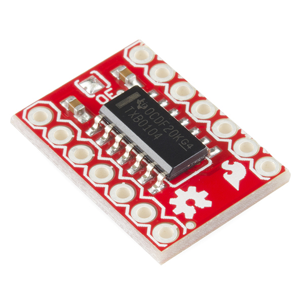
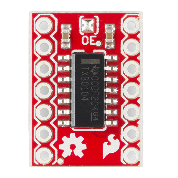
SparkFun Voltage-Level Translator Breakout - TXB0104
This is a breakout board for the Texas Instruments TXB0104 module. The TXB0104 is a 4-bit bidirectional voltage-level translator with automatic direction sensing.
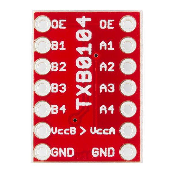
This 4-bit noninverting translator uses two separate configurable power-supply rails. The A port is designed to track VCCA. VCCA accepts any supply voltage from 1.2V to 3.6V. The B port is designed to track VCCB. VCCB accepts any supply voltage from 1.65V to 5.5V. This allows for universal low-voltage bidirectional translation between any of the 1.2-V, 1.5-V, 1.8-V, 2.5-V, 3.3-V, and 5-V voltage nodes. VCCA should not exceed VCCB. We have broken out each pin on this module for you to easily access both the A and B ports.
- 1.2V to 3.6V on A Port and 1.65V to 5.5V on B Port (VCCA ≤ VCCB)
- VCC Isolation Feature – If Either VCC Input Is at GND, All Outputs Are in the High-Impedance State
- OE Input Circuit Referenced to VCC
- Low Power Consumption, 5-μA Max ICC
SparkFun Voltage-Level Translator Breakout - TXB0104 Product Help and Resources
Core Skill: Soldering
This skill defines how difficult the soldering is on a particular product. It might be a couple simple solder joints, or require special reflow tools.
Skill Level: Noob - Some basic soldering is required, but it is limited to a just a few pins, basic through-hole soldering, and couple (if any) polarized components. A basic soldering iron is all you should need.
See all skill levels
Core Skill: Electrical Prototyping
If it requires power, you need to know how much, what all the pins do, and how to hook it up. You may need to reference datasheets, schematics, and know the ins and outs of electronics.
Skill Level: Rookie - You may be required to know a bit more about the component, such as orientation, or how to hook it up, in addition to power requirements. You will need to understand polarized components.
See all skill levels
Comments
Looking for answers to technical questions?
We welcome your comments and suggestions below. However, if you are looking for solutions to technical questions please see our Technical Assistance page.
Customer Reviews
4.1 out of 5
Based on 8 ratings:
3 of 3 found this helpful:
Good for SPI
I tried level shifting an ADXL362 breakout board with resistors and only got garbage out of the board. Then I bought the TXB0104 slapped some header pins on it and installed onto my breadboard and was up and running in minutes. I was able to run my SPI_CLOCK_DIV all the way up to 2 on a 16MHz Arduino and get data from the ADXL362. Since I am going to incorporate the actual TXB0104 chip into a custom board I like the idea of having the four lines taken care of with a minimal foot print and parts compared to using separate BSS138s.
1 of 1 found this helpful:
level shifter
while it might be good, I got confused with level shifter that probably will work for I2C bus. The data sheet of the TI device indicates that this board can not be used for I2C bus level shifting.
1 of 1 found this helpful:
Handy device
This is a handy and low-cost solution to a common problem. One problem I ran into--and it is a problem with the IC, not with SparkFun's breakout board--is that the IC will oscillate if the load on any output is too heavy. If you find that is the case, add a buffer IC downstream of the output.
5 of 5 found this helpful:
I buy these in bulk for our lab
My team is constantly building prototypes which involve combining various off the shelf eval boards with our companies technology and various single board microcontrollers, and thus seemingly always in need of shifting levels between devices. After debugging and evaluating our prototypes, we commonly bring the TXB010X family of level shifters (typically in a smaller package and available in 1,2,4,6, or 8 bit) on to our custom boards which helps maintain consistency for debugging.
This board is a simple breakout board bringing the signals to 0.1" header holes while simplifying the OE connection with a solder jumper to VCCA, eliminating extra soldering work if you simply want this device always-on. In instances where power is critical or it is beneficial to appear as though a bus has been disconnected, the OE pin can be set high by a GPIO to shut down the device and the outputs will go to a high impedance state.
As the TXB0104 is primarily intended for push-pull signals rather than open-drain it works really well for UART and SPI bus applications, whereas for open-drain signals such as I2C, the BOB-12009 is a better option (which I also typically buy in bulk and stock in our lab).
Good for prototyping
Use it with iMX8 UARTs but got some other problems.
No Working
I have not got it working
This works well, but...
This product is easy to use and straight forward; however, TI makes a 6 bit and 8 bit version that should be available. I use this for converting quadrature encoder pulses, which have three signals when also using the index signal. Two encoders are used for a differential drive, meaning I need 6 signals. With this model, I must buy one for each encoder, wasting one bit per unit.
0 of 2 found this helpful:
It didn't worked
I tested but it didn't worked well, then I bought two 74AHCT125 to create an 8 bit level shifter and worked perfectly shifting levels from 3.3 v logic to 5 v .
So sorry to hear that you had some issues with your item.
pro-tip: this might not be the best choice for driving long strands of WS2811 LEDs as the output on this bidirectional chip is not as strong as some unidirectional such as the TI: 74AHCT125
The length of the strand isn't important, as each LED has a repeater circuit built in that reshapes the output. It's the distance to the first LED that matters more.
You're right, though: this is a poor choice for applications requiring high drive strength, say, because of a large fan-out into multiple input devices.
Your explanation makes sense and accounts for the extra variable of distance to first LED that i had not properly considered. In my particular case, it did not require more than about six feet of added wire. I will try to find time to go back and experiment in a controlled fashion with various distances and gather some data.
What is the difference between this and PCA9306 (BOB-11955) apart from the number of bits? I want to use it for 5v-3.3V UART (possibly I2C), so I only need 2bits, but I prefer high speed.
I have two of these. When A and B are connected to a common ground, and the A side has 3.3V (on VccA and A1) and the B side has 4.65V on VccB, the output on B1 is always around 2.2V. What am I missing?
What are the pins connected to? This part has a fairly low DC drive current; if you're trying to drive an LED, it's probably going to pull the voltage down pretty harshly.
Is that across all pins? Does the part function in the other direction (i.e., can you put a signal in on B side and see it on A side?)? It may be that you have a bad board. E-mailing tech support is probably a good idea.
A word of caution: read the data sheet carefully. I got bit by this IC before because I was using it to level-shift JTAG signals, which are pulled up by resistors on the target device. The value of the pull-up resistors was too low, which caused the IC to be confused about the direction of the signals.
The datasheet recommends using 50k pull-up resistors if you need them. It is also incompatible with I2C, 1-Wire, and similar buses.
For I2C, I'd recommend the PCA9306 as a better solution.
https://www.sparkfun.com/products/10403
Not sure how that would work with the JTAG stuff, however.
I'm trying to use one of these to drive some of the 6.5" 7-segment digits with their drivers (5V logic) from a Raspberry Pi A+ (3.3V GPIO). Works great for four digits. When connecting the fifth digit however, the logic levels get murky on both the a and b pins for this board. On the 3.3V side (A pins) the signal gets pulled up a bit and on the 5V side (B pins) the signal floats around 2.5V. The supplies seem steady at 3.3V and 5V so I don't think it's a supply issue. Seems like this board is confused about the direction it should be shifting signals. Any ideas?
Before I connect this I was hoping to get some feedback / assurance. I intend on connecting a 5V LCD to a Mega Pro 3.3V LCD touch screen Mega Pro 3.3V The 5 V LCD screen will be on the VCCB side and the mega pro on the VCCA side Is this correct? All help is greatly appreciated
Perhaps I am doing something wrong, but I need to connect OE to the VCCa in order to get proper logic levels. I didn't remove the jumper. The hookup guide shows the OE unconnected. Please advise.
OE should be unconnected.
There may be a bad solder joint on the board. You can contact tech support and they'll help you figure it out and get a replacement if that's the case.
Hi. For 3.3 <> 5 V UART conversion do I want this or 12009? Thanks a lot.
Either will work; this part is better for higher speed applications so you could save a little money if you don't need the speed capability.
Would this still work from A1 to B1 if VccA was left disconnected? Assuming eveything else is hooked up fine .
I needed to convert from a 1.8V device to a 3.3V device. When the 1.8V was connected connected via unpaired 6" jumper wires, the result was unworkable. Shorter wires (under 1") might have helped, but I went whole hog and ended up doing a custom board with the TXB so that there was only a half inch of PCB trace (with nice ground plane) instead of wires. That seems to work like a champ.
Can this device be used for UART?
Yes, but only for low-voltage UARTs (say, 3.3V signals to 5V signals). For changing between a true RS-232 signal level UART and a low-voltage UART, check out our MAX3232 breakout board.
I tried to put this device in between an AVR mega(@5v) and an XBee module(@3.3v) with no luck. The 3.3v side that was connected to the DIN pin on the XBee was outputting garbage even though the corresponding pin on the 5v side was silent.
That should absolutely not be the case; if you're certain that you've got it hooked up right (especially with respect to the rails; VccB must be the higher voltage), you may want to contact tech support and see about getting a replacement. I've used this board to go from 3.3V to 5V regularly.
Hi Is any body know Voltage-Level Translator with very low level voltage like 0.5 v to 5 and vice versa? Thank you Iman
Can someone tell me the difference between this and the Logic Level Converter?
The Logic Level converter you've mentioned has two bidirectional, open-drain channels by FETs, and two one-way level shift channels (HIGH-In and LOW-out) by resisters doing voltage divider. Bidirectional open-drain level shifters are (by choosing appropriate FETs) compatible with I2C bus, but it has fixed High- and Low-voltage sides. Buffer-gate type bidirectional level shifters like TX010x based ones have two sides and any side of it can be assigned to High (or Low) voltage side, though lines pulled-up may confuse the chip as supersat mentioned above and not compatible with I2C.
This is a great chip - easy to hookup and it just works. No slew. No hassle. I'm really glad to see that you guys made this a breakout board. One word of caution, though. The VCC Isolation feature (which places the pins in a HighZ state) works during startup only if you tie OE to ground via a pulldown. It doesn't matter which rail powers up first, but until the VCCa rail is energized OE will continue to be held low, keeping the pins HighZ. SO - remember to connect OE to GND with a weak pulldown (10-50k), and leave the solder jumper connected.
One of these that can do 12V to 5v would be fantastic. Anyone know of such a chip?
No promises, but from quick glance it looks like Texas Instruments CD4504 might fit the bill. It really depends on what you're trying to do with it. I2C? SPI? Supply from 5-20V. Tie SELECT to GND and you'll have yourself a A-B CMOS translator. http://www.ti.com/lit/ds/symlink/cd4504b.pdf
If you don't need bidirectional, a MAX232 might work. Made for RS232.