- Home
- Product Categories
- Current
- SparkFun Current Sensor Breakout - INA169

SparkFun Current Sensor Breakout - INA169
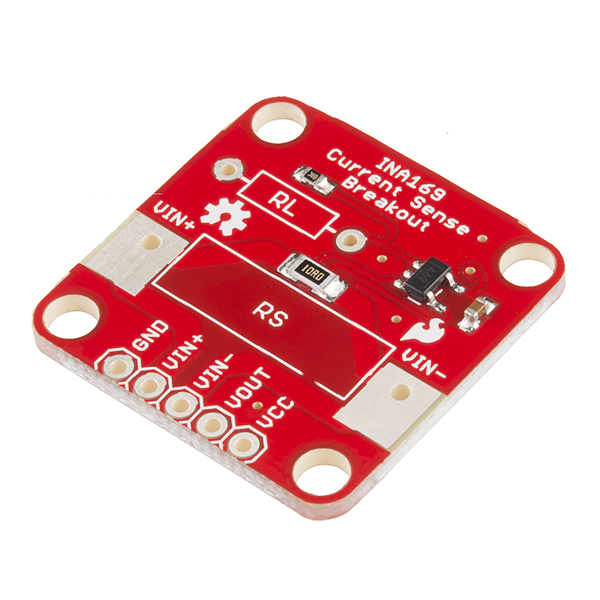
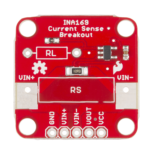
The INA169 is a “high-side current monitor,” which means that you place a resistor (a “shunt resistor”) on the positive power rail and the INA169 measures the voltage drop across that resistor. The INA169 outputs a small current based on the measured voltage drop. If you place a resistor from the output of the INA169 to ground, you can measure the voltage at the output.
Input common-mode and power supply voltages are independent and can range from 2.7V to 60V on the INA169 and quiescent (sleep) current is only 60uA.
- Schematic
- Eagle Files
- Datasheet (INA169)
- Hookup Guide
- GitHub
SparkFun Current Sensor Breakout - INA169 Product Help and Resources
INA169 Breakout Board Hookup Guide
November 20, 2013
How to interface with the INA169 Breakout Board to measure current.
Core Skill: Soldering
This skill defines how difficult the soldering is on a particular product. It might be a couple simple solder joints, or require special reflow tools.
Skill Level: Rookie - The number of pins increases, and you will have to determine polarity of components and some of the components might be a bit trickier or close together. You might need solder wick or flux.
See all skill levels
Core Skill: Electrical Prototyping
If it requires power, you need to know how much, what all the pins do, and how to hook it up. You may need to reference datasheets, schematics, and know the ins and outs of electronics.
Skill Level: Competent - You will be required to reference a datasheet or schematic to know how to use a component. Your knowledge of a datasheet will only require basic features like power requirements, pinouts, or communications type. Also, you may need a power supply that?s greater than 12V or more than 1A worth of current.
See all skill levels
Comments
Looking for answers to technical questions?
We welcome your comments and suggestions below. However, if you are looking for solutions to technical questions please see our Technical Assistance page.
Customer Reviews
4.5 out of 5
Based on 2 ratings:
A useful tool
I would have preferred the pins been wired a little differently (like VIN+ next to VCC) but this is a minor nitpick. Very handy in finding current spikes that are easily missed with a multimeter.
works as expected
was able to do exactly what I wanted to with it. Was able to measure battery current for a Solar Generator I was making. Very Satisfied!
What is the minimum current that can be measured??
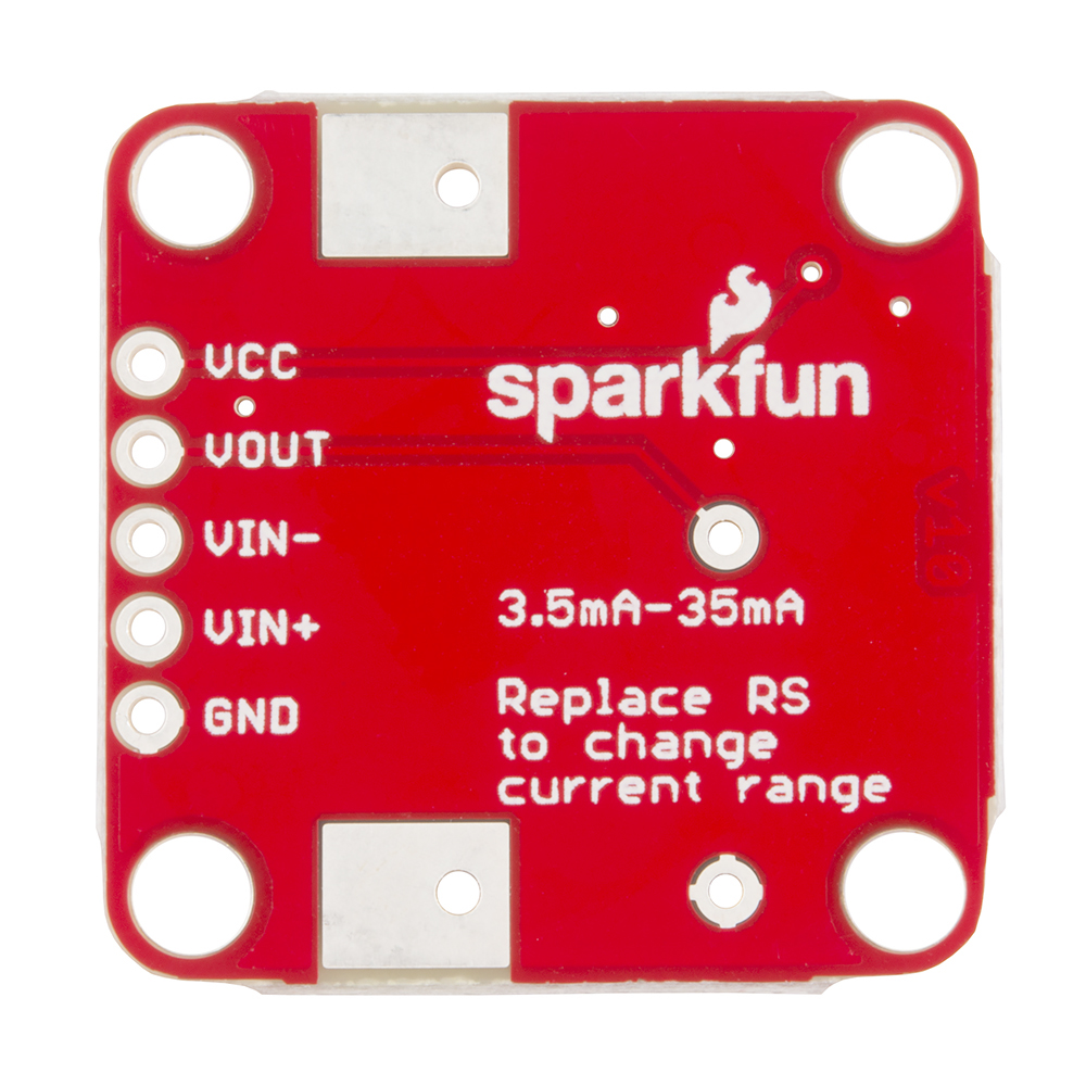
In it's default configuration, it can measure 3.5 mA - 35 mA. You can change the Rs to measure smaller currents; see the Modifying Functionality section in the hookup guide.
Works like a charm! However, just one question... Is it possible to measure from 0 to ~1.5A for example with INA169 with high precision? I saw that changing Rs to 0.1 Ohm will measure from 350mA - 3.5A but I was wondering if there's some other method to measure from 0 (or some other minimal value) up to 1.5A?
You should be able to. You'll need to adjust both Rs and Rl according to the equation Is = (Vout * 1k) / (Rs * Rl). Take a look at the "Measuring Current" section in the hookup guide.
Hi, I'd like to use this in my system, but I am not sure what value to choose for RL and RS. I want to measure max. 42VDC at max. 30A. Can you give a suggestion for resistor values and ratings? Thanks!
If you take a look at the equations in the Hookup Guide, you'll see that you can leave RL at 10k. By lowering RS to something like 0.01 Ohm, you should be able to measure between 3.5 and 35 A. However, note that with 30 A of current, your resistor will produce around 9 W of heat, so you'll need a pretty beefy power resistor.
I bought three of these and all of them were DOA. Customer support also has been unresponsive for the past three weeks.
Sorry to hear that. I will make sure someone sees your request.
I'm having difficulty calculating Rl. I have a the following: Vin+ = 12-30v Is = 0-150Amps Rs = 0.25mOhm Output voltage range needs to be 0-3.3v
I'm confused by the formulas in the datasheet, and the formula Is = (Vout * 1k) / (Rs * Rl) does not provide a value that makes any sense. Can anyone shed some light on this for me? Thanx.
First, what is the voltage of your sensing line? The max common voltage allowed (either Vin+ or Vin- compared to ground) is limited to 60 V (according to the datasheet).
To calculate the max Rs = 0.5V / 150A = 0.0033Ω . 500mV taken from the max "sensing voltage" (Vin+ - Vin-) in the datasheet.
From that, we can calculate Rl: Is = (Vout * 1k) / (Rs * Rl). 150A = (3.3V * 1k) / (0.0033Ω * Rl). Solve for Rl = 6.6kΩ (closest resistor is 6.2kΩ, which allows you to measure up to 161A).
Note that if you look at the error graph on p. 4 of the datasheet, if the differential voltage (Vin+ - Vin-) drops below 25mV, you'll start to lose accuracy. That means your measurement is really only good between (.025V / 0.0033Ω) = 7.6A and 150A.
Does that help?
Excellent. Thank you. I was getting confused by the 1000uA/V value in the calculations.
Works like a charm!
In case this saves someone some time (since I just worked this out the hard way)... you can't use a current sensor with a stepper motor. Stepper motors run at full current all the time (so they can lock their position) so you can't detect (for example) an increase in current draw with an increase in load for current-control of the motor.
OK this is great for DC. But What about low voltage AC (24V- 12V AC), is there a Current Sensor chip for that?
You can actually use this for AC if you want, it'll just read 0 during the negative portion of the waveform. You can, in fact, use TWO of these, back to back, as it were, so one of them is giving you a current reading on the positive portion of the waveform and the other one on the negative portion.
There are some useful guidelines for this in the datasheet, but it's a pretty advanced topic, which is why we left it out of the tutorial.
Also, check out the ACS712. It's Hall-effect based, so it's got less of a burden voltage, but it's sensitve to local magnetic field distortions, especially at high gains.
I am curious why this was designed around the INA169 instead of the INA219? The INA219 has an internal ADC and an I2C output that provides the current and voltage values directly. The INA219 makes dealing with current measurements in a microcontroller project very easy. The common mode range on the INA219 is a bit lower at 26 volts but this is fine for the majority of applications I would think. INA219 based breakout boards already exist from other suppliers but it would be preferable to be able to get them from Sparkfun.
The INA169 is definitely a cheaper chip, and using a microcontroller's ADC isn't all that bad (you also get to use 1 pin instead of 2). From an Arduino perspective, that's an analogRead() vs. the initialization of the Wire/I2C library. That being said, if there is enough interest for an I2C current sensor, please let us know! It would be something worth considering.
Sure, I agree it definitely can be done with a microcontroller's on-board ADC and I suppose "all that bad" is subjective. But, to do it right requires a properly designed anti-aliasing filter and accurate voltage reference. Surely everyone who is going to use this with their Arduino understands these analog design issues and properly accounts for them right? Just like SparkFun did in the tutorial, right? Sorry about the sarcasm there but, without an anti-aliasing filter and true voltage reference you have no idea how accurate the reading will be.
Your basic Arduino setup is using it's own power supply as a voltage reference for the ADC right? How accurate is that, five percent, ten percent? How much noise does it have, how much does it vary under load? In contrast, the INA219 has an internal high accuracy referencer and proper filtering built in, is listed as 0.5% max over the specified temperature range, and provides both current and voltage measurements with this accuracy.
As for the number of pins used, the INA169 requires one ADC pin for current and a second if you need voltage measurement as well. So, one or two per channel. The INA219 requires zero additional pins if you already have any other I2C peripherals or two pins if not. Each additional channel requires zero additional pins up to 16 channels when you run out of unique addresses.
The INA169 is a perfectly fine chip when properly implemented but how many people who attempt to use this product will truly understand and address all these issues. The INA219 takes care of all the messy analog details for them and will be far more accurate for your average user.
As for whether there is enough interest I cannot say. For me though, the digital output high-side current sensor is something that is worth it at two or three time its cost. To get that kind of accuracy with a microcontroller's on-board ADC is not trivial and I would not even consider attempting it for other than general order of magnitude type measurements. One can easily find a breakout board with an INA219 available online for only slightly more than this one so it just puzzled me, with something so much better already available why SparkFun would design this product around this chip.
You can limit the output bandwidth to create an anti-aliasing filter with just a slight modification. If you look at figure 3 in the datasheet they show this application. You could replace the the smt resistor with a cap and put a through hole resistor in for Rl or just stack a cap on the smt resistor. Now you have to consider the RC time constant vs settle time needed for your adc (not sure what the arduino is 12 bit maybe?) and adjust your sample rate accordingly and still meet nyquist from your stopband. Not trivial but can be done.
Your points are valid, however I am not sure how many people need the resolution you are discussing.
Add me to the I2C interest list. If you already using the I2C then adding another I2C chip to your project is not really that big of a deal. I am frustrated that SF seems to try to add to the hype of how bad I2C is to use. It's not. I rather use I2C chip if there is a version that all ready takes care of all the heavy lifting then forcing me to write all the code to do the same job and takes up another pin on my Arduino. Shawn- you got to realize taking up two pins on the Arduino is a lot less then taking up 4 or 10 to do the job of two or more I2C chips. Plus if you really don't like wire library there is an alternative to it over at http://dsscircuits.com/ for I2C.
Add me too!
I have some INA169 and INA219 boards. I think they suite different situations.
INA169 1.) You can visualize the signal on your 'scope and prototype your filter (if necessary). 2.) No separate 5/3V supply and the overhead of a microcontroller required (think motor control board). 3.) No cable length limitation. 4.) It just works.
INA219 1.) No filter design overhead. 2.) Bus voltage and power sensing for free. 3.) Easy to integrate into microcontroller project at the cost of being able to see the signal without first tracking down a micro, code to make it work, and power supply. 4.) Limited cable length. Running i2c bus at long cable lengths (say >1.5 meter or so) requires attention to bus speed, capacitance, load, and some other details that make the level of effort too high for most people.
Overall, the INA219 seems like it adds a lot of things that stand between the user and his/her information. Especially if you are doing hobby level electronics (Sparkfun's target customer).