- Home
- Product Categories
- Sound
- SparkFun Sound Detector

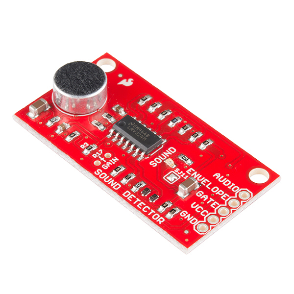
SparkFun Sound Detector
The SparkFun Sound Detector is a small and very easy to use audio sensing board with three different outputs. The Sound Detector not only provides an audio output, but also a binary indication of the presence of sound, and an analog representation of its amplitude. The 3 outputs are simultaneous and independent, so you can use as many or as few as you want at once.
The envelope output allows you to easily read amplitude of sound by simply measuring the analog voltage. Gain can be adjusted with a through-hole resistor, to change the threshold of the binary (gate) output pin as well. Check the hookup guide below for more information about setting gain.
Each of the three output signals is present on the .1" pin-out at the edge of the board. They are active simultaneously. If you aren’t using one in your particular application, simply leave that pin disconnected.
- Schematic
- Eagle Files
- Datasheet (LMV324)
- Hookup Guide
- GitHub (Design Files)
- Product Video
SparkFun Sound Detector Product Help and Resources
Sound Detector Hookup Guide
February 27, 2014
The Sound Detector is a microphone with a binary output. This guide explains how it works and how you can use it in your projects.
Hackers in Residence - Sound and Motion Reactivity for Wearables
October 3, 2014
How to consciously wear light-up and and sound reactive clothing.
Sound Reactive EL Wire Costume
December 31, 2015
Learn how to make your EL wire costumes sound reactive in this project tutorial.
Rotary Switch Potentiometer Hookup Guide
April 30, 2015
How to use the Rotary Switch Potentiometer breakout board, with some sample applications.
Hackers in Residence: The Sound Visualizer Pt. 2
May 7, 2015
An addition to a previous project, this time using a PC and a custom Java app to create your own music visualizer using a RGB LED matrix.
Interactive LED Music Visualizer
May 31, 2016
Use an Arduino and the SparkFun Sound Detector to create visualizations on Addressable RGB LED strips.
Hackers in Residence - The ElectricBone
June 25, 2014
Drum machines and keyboards have been the standard for making digital music, but how do you make electronic music if you're trained to play the trombone? One of our Hackers in Residence, Carlos Mello, took it upon himself to find a solution to that very question.
Core Skill: Soldering
This skill defines how difficult the soldering is on a particular product. It might be a couple simple solder joints, or require special reflow tools.
Skill Level: Noob - Some basic soldering is required, but it is limited to a just a few pins, basic through-hole soldering, and couple (if any) polarized components. A basic soldering iron is all you should need.
See all skill levels
Core Skill: Programming
If a board needs code or communicates somehow, you're going to need to know how to program or interface with it. The programming skill is all about communication and code.
Skill Level: Rookie - You will need a better fundamental understand of what code is, and how it works. You will be using beginner-level software and development tools like Arduino. You will be dealing directly with code, but numerous examples and libraries are available. Sensors or shields will communicate with serial or TTL.
See all skill levels
Core Skill: Electrical Prototyping
If it requires power, you need to know how much, what all the pins do, and how to hook it up. You may need to reference datasheets, schematics, and know the ins and outs of electronics.
Skill Level: Rookie - You may be required to know a bit more about the component, such as orientation, or how to hook it up, in addition to power requirements. You will need to understand polarized components.
See all skill levels
Comments
Looking for answers to technical questions?
We welcome your comments and suggestions below. However, if you are looking for solutions to technical questions please see our Technical Assistance page.
Customer Reviews
4.7 out of 5
Based on 20 ratings:
1 of 1 found this helpful:
Love it!
The gate and envelope pins are what set this apart from everything else I could find out there. The process of adjusting the gain was a bit daunting to me at first, but it's actually very easy!
Definitely would recommend this to anyone looking to add live audio input to their project.
3 of 3 found this helpful:
Sound detector
I soldered this to an Arduino 101, with external power supply, its O.K., but with power supplied from USB cable, it constantly detected a sound, because the USB power supply is so noisy. I add a bunch of caps to VCC to GND,, this improved situation somewhat, but still pretty bad as gain was increased. I wish unit came with a built in pot to control gain. I also wish unit has better power supply filtering and/or an onboard linear regulator to help with higher gains. I also removed the microphone, to attach to my hydrophone. it worked great to detect sounds underwater in a jar of water, but it a pool, the detection would never turn off.
1 of 1 found this helpful:
Works great made it easy
It was exactly what was needed and works great for my project to detect sound. I do wish they had a built in gain variable.
1 of 1 found this helpful:
Envelope is the bomb ...
I've play with a couple different sound boards, but I enjoy the envelope signal from this one. It simplifies some of the code when doing the A/D conversion.
1 of 1 found this helpful:
My son used these sound detectors for a graduate Computer Science project at UC San Diego for a class on Embedded Logic. He set the gain so the detectors would only hear noise above 110dB, so they could detect gun fire. He used multiple sensors to determine which room of a building the gun fire was coming from. He successfully tested his system with a starter pistol.
1 of 1 found this helpful:
Sound Detector
Good response, adjustable gain, three separate outputs, excellent manual, low price. Does need a very clean and very stable power source.
1 of 1 found this helpful:
A Well Designed Module Ready For Integration
Power, analog and envelope outputs. Easy to integrate into subsystems. Works right out of the box
1 of 1 found this helpful:
Fantastic for IoT projects
Great sound detector for Smoke Alarm / Door knock detection in IoT projects. Simple and effective way to test systems.
Link below for anyone looking to set up an IoT system with a Raspberry Pi Node Server. I do not make any money off there videos nor will that ever change. I do them for my students and anyone else interested.
Bottom of playlist is Sound Detector
https://youtube.com/playlist?list=PLlnL61QfD9UbcGw8Oxz-KtOhbSqJ4oTW1
3 of 5 found this helpful:
Great Design
The LMV324 used in the design of this microphone bord is great, however, the gain has to be controlled especially if you are using long lines to connect it to other devices. I used a 100k potentiometer instead of a fixed resistor to populate R17. This allowed me to adjust amplifier gain right before the output starts to oscillate. I am using this board to fire camera, flashes etc when photographing gun shots, balloon pops and any other noise induced event. It is just great since it is compact and can be housed in any small box. I housed mine in an empty prescription vial. I am running 20foot wire so I ran the output into TC4428 and it was just what the doctor ordered. Now I can run a very long line and still have a good control over the gain. I am using Schmitt trigger output only.
1 of 2 found this helpful:
A very useful audio tool.
I have owned four of these bad boys, and only one of them has broken. However, I am moving these things around a lot so bad transportation may have been a cause. Make sure as any other chipboard to solder in the connections properly. Still learning about the possibilities of this tool.
1 of 2 found this helpful:
Has met and exceeded my expactations
1 of 2 found this helpful:
Buena calidad
Gracias a toda la circuiteria solo es conectar a tu MCU y estara funcionando
1 of 2 found this helpful:
easy, effective
i used this sound detector for my MFA thesis exhibition installation piece and it works beautifully. so easy, so effective. it would've been much harder to pull off with something else!
Great sound switch
Works as advertised.
Worked perfectly for what I needed
I used this little sound sensing board to Macgyver together an interface between the sound output from a motion sensor radio to a zwave open/close sensor. This allows me to have a smart home trigger to outdoor movement near my motion sensors. There are a lot of ways I could have done this, but using this sound detector board was simple and so far it has been very robust. Next I think I will use another one to trigger when someone presses my doorbell.
Works just fine
I tested this unit out and it works reliably with no false triggering. The only caution about using the unit is to make sure that if your project generates an audio output that the output does not activate the unit. This can easily be done if you are using a microcontroller by inserting a few second delay in continuation of the program after the audio alert. If using a 555 series device, the audio output could start an additional stage to prevent the triggering. If using this with a 555 series device, note that the output of this unit is active high, whereas the 555 is active low, so that will have to be accounted for. It is very nice to have the additional ouitputs for troubleshooting.
little sound detector
This detector works quite well. I like the digital output that I can use to TTL circuit.
Question regarding the Gate output on the sound detector breakout board.
How short of a duration sound event (of adequate amplitude) will trigger the Gate output to go HIGH?
Then, how long will the Gate output remain HIGH after the sound event is over?
I'm trying to detect each tone in something like a fast-busy signal you might experience in telephony. So would a tone sequence that is say a repeating pattern of 100ms of sound followed by 100ms of silence followed by 100ms of sound ... show up as essentially a 50% duty cycle square wave on the Gate output? Or does the Gate output remain HIGH for a duration after the sound has stopped that would prevent rapidly repeating tones with an On/Off pattern from being detected as individual sound events?
Hey gang, do you guys know if the envelope output is linear with respect to loudness (decibels)? That is to say if I do a two point calibration at "silent" and 94dB, how much error should I expect by linearly interpolating between those two voltages to convert to decibels?
For the purposes of this question, lets ignore the frequency response of the microphone (i.e for a constant tone, e.g. 1kHz).
Hi there! Can this be used for detecting heart sound?
Hey i am using this on Raspberry pi 3 and i connected envelope's output to ADC but when i read values from ADC i get a very low value 0.087646.... so is this a db value or volts?
Hello. I am implementing only a fraction of this design. I wish to use another IC for the op amps. Does anyone know if that is going to require much redesign? After initial testing I'm left unsure if the design is going to work "as-is" except with an MCP6004 IC instead. I think that I am looking at good results on my o-scope but me turning the knob on a power supply is probably a poor simulation of a microphone lol. It's for a friend who runs an educational camp. I'd appreciate any advice. Thanks.
I'm just getting started testing this. It is currently hooked up to a Raspberry Pi 2 and has a script to just run until 3 sounds are heard. The detector seems to work as intended (LED flashing with noise) when the script is not running. It is only connected to 5v, gnd, and gate right now because I just want to get the script to work. The problem is that when I run the script it instantly starts firing the LED and the 3 sounds are heard almost instantly (3 loops of the script). The raspberry pi is plugged into a wall power supply but still obviously going through a micro USB-USB cable. Any idea why my script would actually register sound?
I have this sound detector powered by two 3V COIN CELL BATTERIES (with a diode to drop voltage down to 5.3V), and it doesn't function properly. The red LED turns on and stays on until power is switched off. Why does this happen? Is it a current issue? (when I switch to 3 AA batteries the sound detector works fine). Please let me know if you have any insight about this so I can modify accordingly. I really would like to use two 3V coin cell batteries.
I want to make a dB meter, but I still don't quite get it. I need to measure in a range of about 50-90 dB.
If I use the envelope pin as input in a 12bits ADC, I can only measure untill max 72dB? This means I have to adjust the gain a bit because I can't reach the 90dB.
When I use a R17 of 47K I get * Arithemetic Gain of 32 * Gain (dB) of 30
But how do I now know what range I can measure? (0 to >72) ? And how do I calculate the ADC value into dB?
thanks
I have this connected to analog input of a spark core (similar to arduino) and I am trying to figure out a formula to measure decibels. The formula I'm using must be incorrect because I am not getting readings that correspond with decibel ranges. Can you tell me how you are measuring decibels with your sound detector? FYI, here's the formula I'm using:
(20 * ( log ( voltage1 / voltage 2) ) ) -- voltage 2 is a constant, voltage 1 is the analog read. Thanks!
For both of these cases, members #614529 and #614799, you'll need to calibrate the sound detector.
First a little background:
dB can be a bit confusing as a unit, because by itself it only refers to a relative change between two things. The actual unit gets a suffix that indicates a particular standard reference - dBSPL indicates the acoustic pressure of sound, dBm, dBV and dBu refer to different electronic cases. Just "dB" by itself refers to a relative change.
I think this may be contributing to the confusion. In the sound detector hookup guide, the numbers for dB are being used to express how much voltage gain the amplifier is providing - the relative change between the input voltage and the output. If the put a 1Vp-p signal in, and a 2Vp-p signal comes out, we can say that it's been increased by 6 dB, relative to the input level...but not relative to any specific standard.
The Wikipedia page for decibels contains a number of examples, and further references to specific versions of dB.
So back to the problem at hand: it sounds like you both want to calibrate the sound detector in terms of meaningful dBSPL. There are a couple of ways to do those, but both require some external hardware.
The first way would be to use a reference SPL generator, such as the Amprobe SM-CAL1. You place it over the mic, and flip the switch to generate a known amplitude sound. You can then read the ADC, and you have a baseline calibration - "voltage 2" as noted in #614799 's posting.
So, assume you used the 94 dBspl setting on the Amprobe device linked above, and you read (pulling a number out of thin air here), 123 from the ADC. Then you take the sound detector somewhere else, and read 168.
The equation given above is correct, so plugging in these values:
20* log(243/123) = 5.9 dB above the reference of 94, or 99.9 dB.
The second way would be to compare the sound detector against some external SPL meter. Here's one example, or check for an app if you have a smartphone handy.
With some sort of steady state tone or noise, hold the meter and the sound detector near each other (like holding them in front of a stereo speaker), then note both the dBspl reading from the meter, and the ADC reading from the sound detector. This is the calibration reference you can use as we used the 94 in the above equations.
Hi Byron, thanks for these detailed instructions! I am just getting back to the project now, I'll be following along and let you know if I have any questions. Thanks again!
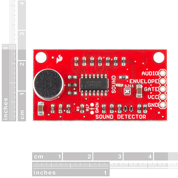
I want to design a board I can plug this into, but I need it's actual dimensions, and they aren't mentioned at all in the product description and I can't open the eagle files because I don't have access to eagle at the moment, so I just need the width and length
It is 1.7" by 0.9".
The mounting holes are at (0.1, 0.8) and (1.6, 0.8).
The 5-pin connector is from (1.65, 0.2) to (1.65, 0.6) on 0.1" intervals
Please help me in the conversion of ENVELOPE output to dB....please...
Any help me to convert the ENVELOP output of this module to dB. Please..
Already bought a few of them and am thinking of getting more. Before I do, though, I have a question.
I read the Hookup Guide for this product (which is excellent, btw), and I understand that to increase the gain, you remove the R3 resistor and add a resistor to R17. Starting with 100K and up to 1Meg, the larger the resistor, the higher the gain. Cool!
But what if I want to be able to adjust the gain without having to re-solder? Is it possible to use a potentiometer (rheostat?) instead of a through-hole resistor so that I could have a knob that adjusts the gain of the microphone?
Basically, I'd like to avoid adding something that forces me to have fixed gain and figured a variable resistor could do the trick. Am I on the right track here? Any confirmation and/or additional suggestions would be great.
Thank you!
Yes, by all means. You can put in a pot, rheostat, decade box, rotary switch with discrete resistors, etc.
If you look at the gain range table with R3 removed, you'll notice that R17 doubles for every ~6 dB added gain - you'll want to use a configuration that matches that resistance increase.
Ideally, a 1 Meg reverse-audio taper pot would be the best fit, and would give you smooth control over the gain range. If you set up an audio taper pot (AKA log taper), and put it in backwards, you'd have similarly smooth control, but you've have to turn it counter-clockwise to increase the gain.
With a linear taper pot, you'd find that most of the gain range was all bunched up at one end of the throw, and only changes a tiny bit over the rest of the rotation.
Hey. I was wondering if i could do the same with these sensors?
https://www.youtube.com/watch?v=n2cBGXsOREU&list=LLSIUZji9F8DwKx6wZH2DvRA&index=1
To do exactly what they're doing in that video (performing audio cross-correlation), you could use the audio output of the sound detector - at that point, it's essentially a fancy microphone, and a plain electret mic would do the same job.
If you're trying to localize a transient sound, you could time the difference between the gate outputs of two sound detectors (perhaps using the input capture feature of a microcontroller) - but that won't work for steady-state sounds, because the gate would always be active.
I'm hoping to use this to give an equalizer lighting effect. Louder sound input, higher voltage and more pins triggered for the lighting display. Am I right that I'd use the envelope output as the input to the arduino?
I also think I need to add the resistor mentioned since it will be in a louder environment. Thanks.
If you want a voltage that corresponds to the sound amplitude, the envelope pin should do that.
There's an example sketch using an Arduino to read the envelope pin in the hookup guide.
You're probably right about adding resistors. It will help keep loud sounds from overloading the output. If it's possible, you can test out resistors by tack-soldering them in, or even just holding them carefully in place.
When I first tried one of these sound detectors, the red light stayed on continuously. Apparently, it was too sensitive. I want to use it where noises are very loud, noises that go over 80db, often up to 100db. After reading directions, I soldered a 2.2K resister into the R17 slot, after which the red light wouldn't light up until it detects a very loud, sharp noise. Now I will have to de-solder the 2.2K resister, and replace it with a larger resistance. But I think I will use a variable resistor in its place. BTW, its quite difficult catching the detector's waveforms on an oscilloscope, and they don't quite match the waveforms illustrated in the hookup directions.
the noise immunity of this circuit is laughable at best. hooking it to vcc/gnd of an avr and letting the avr switch ~50mA (led a led bargraph) will trigger the gate led. operation depenend on input voltage. this is another badly designed circuit.
What is the unit of the enevelope output? Is the value I get there directly dBs or something different? I am trying to make a simple Sound Meter.
The envelope is an approximation of volts peak-to-peak. It's not calibrated to any particular unit or absolute reference. The inexpensive microphone on the front end has fairly wide tolerance on its sensitivity, meaning every unit responds a little differently.
To make a simple relative dB meter, you could read the envelope using the ADC on a microcontroller. Binary encoding actually forms a shorthand for decibel levels - each successive bit position in the conversion value equates to another 6 dB SPL. It's coarse, but not very hard to do.
Thank you, that works pretty well! Also, that would technically mean that it only measures up to about 66db (if the starting point is 0dB). Is that correct?
More or less, depending on the data width from the ADC - every bit in the output gives you another 6 dB. 66 dB range equals 11 bits of ADC data, a 12-bit ADC might get you to 72. Much beyond that, and you're probably limited by the self-noise of the system.
You could extend the overall range by adjusting the gain resistor. I've got an old analog SPL meter that does that. The needle only reads over a 16 dB range, but it has a range switch that adjusts the gain to re-center that range on 10 dB increments, from 60 to 120.
Sweet. Last question, I swear, what is the formula to calculate the range from a newly adjusted gain (I saw how to properly adjust the gain on the board in your tutorial)? (I am trying to measure airplane engine noise, talking more 90 - 120dBs).
The gain adjustment is an inverting opamp stage. The giverning equation is
If we assume that we're putting in 1 Volt, then we can simplify to just the ratio of the resistors
-(Rf/Ri). This coefficient is referred to as the "arithmetic gain" of the circuit - input voltage will be scaled by that factor to become the output voltage.For the default configuration, that's -100k/1k, which simplifies to a factor of -100.
To convert arithmetic gain to relative dB, use the following equation:
The default configuration gets the gate to trip on moderate sound levels, maybe around 70 dB SPL. If you want to work in the 90 to 120 range, reduce the gain a bit - try a 10K or 22K resistor for R17.
Thank you! That was a very helpful and very knowledgeable answer.
can i desolder the mic and solder on wires that i connect to a computer headphone output? i need a circuit to close when audio signal is present.
thanks in advance.
Yes, that will work. I've seen one of our QC techs do exactly that.
You'll also need to take off R1, the 2.2K resistor, or else you'll be feeding Vcc to your headphone socket.
in order to get a contact closure, would i use the envelope output to actuate a small relay?
The gate output will give you a more suitable signal for switching.
You'll probably also need to use a transistor to get the relay to trip, and a diode to protect the circuit when the relay turns off, Take a look at how it's done on the Breefcake Relay schematic.
I want to build a device to extend the range of my apartment's door buzzer so that we know we're being buzzed when in the backyard.
I was thinking of something that would mount on the wall next to the intercom/buzzer box in my apartment, listen for the specific tone that it makes, and then send a signal to a bell or buzzer that would live in the backyard (I think it would be super cool to make this an actual bell that rings, but I'll take what I can get). Obviously I only want the outdoor bell to ring when the buzzer rings.
Do you think this product would work for my application? Any thoughts on what else I'd need? Or if this is the wrong place to ask such questions, any suggestions where I should go? I'm a complete beginner at this stuff, so I would really appreciate good advice.
I'm very grateful for any help!
NOTE: just to save time, please know I am aware of wireless doorbell extenders and the like, but they won't work for my application. I can't touch the wiring of my intercom system, AT ALL.
Since your question is pretty tightly related to this product, this is an OK place to ask. You might also check out our support forums...I've learned a lot through the years just by hanging out on forums, and watching the conversation unfold.
The sound detector should work to detect the buzzer sound - just put it near the buzzer. You may need to adjust the sensitivity, as covered in the hookup guide.
One thing to consider is that it will also pick up other sounds - if the buzzer is the loudest thing in the room, you won't have to worry about false positives from music or the TV or conversation. Just set the gain of the detector to pick up the buzzer.
What you do from there depends on your interests, abilities and comfort level.
You could actually ring a mechanical bell - you can still find doorbells with real bells on them at hardware stores...or if you can't find one, you could make your own with a small bell (google for "desk bell", about $5 at office shops), and rig a solenoid to strike it. Either way, you'll probably need to use a transistor or MOSFET to drive the solenoid, as the sound detector probably can't provide the current needed to drive it directly. Reference circuit 12 in the SparkFun Inventors Kit booklet for a sample transistor circuit - replace the motor with the solenoid.
An alternative would be to do everything purely electronically, but you probably need to generate a tone to drive a speaker. You could use a small microcontroller to generate a PWM wave, or a simple oscillator circuit like a 555, either activated by the gate from the sound detector.
Also, with a microcontroller in the system, you could generate ring or beep patterns when the buzzer sounded.
You'll also need a power source of some sort - batteries or maybe a wall-wart. Personally, I'd also include a switch so it can be turned off. I wouldn't it to beep or ring if I wasn't outside.
Wow! Thanks for such a detailed and useful reply! It's very kind of you and I really do appreciate it.
If I can ask one more question, I sort of had an idea that because, as it says in the description:
I might be able to use it to essentially take a reading of the buzzer's sound, which I could then use in some code on an Arduino (or similar) to prevent false positives. So in other words, the Sound Detector would send a constant stream of sound info to the Arduino, which would then look at the waveform (or whatever it's getting) and ring the bell when it spotted a matching signal to the one I had recorded originally. Is such a thing even possible with this product?
I might be in way over my head here. If you think what I'm suggesting would require advanced skills - which I don't possess (YET) - feel free to tell me, and I'll go the more straightforward route.
Thanks again for your excellent help!
Josh
My general recommendation would be to not over-complicate things before you get started. Try something simple, identify its shortcomings, and then address them.
The more you experiment, the better grasp you'll have on the problem. I like to start by proving the basic concept, then refining. In your case, get the outside buzzer/bell working, then get it to trigger from the sound detector. If you need to make the sound detector more specific to just the buzzer, you can add that on top of the parts you've already got working.
The sound detector could drive some sort of oscillator (actual hardware, or a software-controlled one with a microcontroller), which could drive a small speaker or piezo.
Alternately, you could simply set up a microphone near the buzzer (like the sound detector's audio output), and relay the sound to an outside speaker.
The biggest variables come down to the specifics of your situation - how loud the buzzer is in the room, how loud other sounds are relative to it, and how close you can get the sound detector to the buzzer will all factor into it. If you can set the detector up really close to the buzzer, perhaps with a baffle to keep other sound out, so that the buzzer is louder than everything else, the gate output will be fine.
Sound recognition as you describe probably takes more resources than an Arduino has. A simpler approach might be to use a hardware counter in the Arduino as a frequency detector, looking for the specific frequency of the buzzer.
Byron,
You commented below on helping me alter this design for picking up shock waves from rifle ammo. You mentioned that the first stage has a hi pass filter using C2/R2. What are the equations for low pass? I am hoping the shock wave is so loud that the mic will pick up the SPL.
Also, how did you get 80nF when you substitute C for R17? I get 1.6uF for 1Hz. Did you use 1Hz?
You said make R8 smaller for lower frequencies. Do you think 10 ohm is too small?
Thanks again.
Hey - are you trying to build an automatic scoring system for standard 72 inch target frames? I've been pondering building the same thing. Have you gotten very far?
Subbing 80 nF for R17 would give you 19.9 Hz lowpass function. If you really want 1Hz lowpass, 1.6uF will do it.
But you'll also need to scale the hipasses formed by C2 & R2 and C4 & R4. At the moment, they're both at 15 Hz. There isn't really much of a passband with a 15 Hz hipass followed by a 1 Hz lopass.
The filter equations are:
The peak detector is probably better expressed in terms of rise/fall time, than pass frequency.
R8 could even be 0 Ohms, if you want really fast peak detection. R8 and R9 were selected based mainly on aesthetic behavior. If R9 is too small, you may not see the LED blink, even when the output trips, and if R8 is small, the output becomes fairly glitchy. It acts as a degree of noise reduction.
OK, here's my project: I'm putting this sound board into a helmet I'm making for Comiccon. (let's say Darth Vader for the sake of simplicity)
Now in order to simulate Vader's voice, I'm running the audio output pin through a mini guitar effects processor (Korg Pandora Mini: http://www.korg.com/us/products/effects/pandoramini/ ) and I'm trying to take what's coming out of the Pandora (either from the stereo headphones or the mono 1/4" Jack/TRS outputs) and put it in a speaker that's also going to be hidden in the helmet, projecting forward or downwards.
I have 3 models of small speakers, including 2 from SparkFun (COM-09151 and COM-10722) and 1 in between those. I also bought the Small Surface Transducer (COM-10917) to try to see if I can use the resonance/vibrations of the plastic helmet as a sound-conducting device.
Now, I also have purchased the (BOB-11044) Mono Audio Amp Breakout with TPA2005D1, as I was foreseeing that the Pandora probably needed help to increase the gain in order to have enough volume out of the speaker.
Finally, everything is powered by 4xAA new Energizer rechargeable (1.25V) in a Battery Holder (PRT-12083). Measured ~5.0V on my meter.
I connected everything successfully, but here's my PROBLEM: Whenever I start getting enough volume, I get INSANE FEEDBACK. Now I understand that this is caused by the speaker going back into the mic, and so on, creating the infernal loop. This happens even if I put a good distance between the speaker and the mic, and if the speaker projects away from the mic.
When I use the headphones (instead of the amp+speaker) on the Pandora, it works flawlessly. Plenty of volume. So I infer that any gain problem would be AFTER the Pandora.
I feel that if I increase the gain on the Sound Detector or the Mono Audio Amp, it will just amplify the feedback... (didn't try it, but that's my guess, as changing the volume knob on the Pandora has that effect. Right now, feedback starts at volume 8/10 on the Pandora)
So... What can I do to eliminate this feedback, and keep a tiny footprint?
Is there a small board that eliminates high frequencies? (LP filter? EQ?... other techniques?)
Thanks for any help.
Ahh, feedback. My old nemesis. We meet again.
Your analysis is accurate - it's the sound coming into the speaker, then back into the mic. From the perspective of feedback, gain is gain. It doesn't really matter which stage applies it...the preamp on the sound detector, the Pandora, or the mono amp. Another decibel louder is another decibel louder.
There are several approaches used to circumvent feedback. They aren't always universally applicable, but each is worth experimenting with, or perhaps trying in tandem.
First, adjust the physical proximity of the speaker and mic, if you can. Break the path that the sound waves are traveling. If you could put the mic inside the helmet, seal it sufficiently, then place the speaker outside (like in Vader's chest pack or belt), connected in such a way that the sound and vibration don't come back to the mic. It's also worth a mention - it might not be sound waves traveling in air causing the feedback, but instead vibration coming physically through the structure. The tighter you connect things together, the more prevalent this phenomenon will be - likewise, looser, more resilient connections will tend to help prevent mechanical transmission. Of course, this approach runs somewhat counter to your thought of using the surface transducers.
Second, we get into filtering. If we can remove the problem frequency, it won't feed back. On large sound systems, 31-band graphic equalizers are used - you find the frequency of the feedback, and turn down the corresponding slider. The EQ is being used as a bank of notch filters. If the feedback is always the same frequency, you might be able to make a passive notch filter to remove that frequency.
Can the Pandora do both your FX and a notch filter at the same time? That would avoid adding any more components.
If not, there's a simple passive notch in Horowitz and Hill's Art Of Electronics, or see what Google comes up with - the twin-T or bridged-T topologies might be worth hunting for. If the frequency is extremely high or extremely low, a simple hipass or lopass filter might remove it.
Filtering can be a little bit tricky. If there's enough loop gain for one frequency to ring, there's probably enough that other frequencies also want to ring...you solve one only to reveal the others. Also, depending on conditions, the frequency might not always be the same. Other factors like humidity, the exact orientation of the speaker and mic, and the acoustics of the room you're in might alter the frequency.
Third, a somewhat more esoteric approach would be to add a bit of delay. Feedback occurs when the sound travels around the loop almost instantaneously. Even a short delay, like 50 ms delay might keep it from happening. You might also find a short delay like that really disorienting and hard to talk through. Worth a try, though.
You might work through various parameters inside the Pandora. If you've got any distortion, guitar amp modeling or compression running, try turning them off. Guitarists sometimes like it when their amp is right at the edge of feedback - it allows them to get long sustain. Compression can make quiet sounds louder, thus more likely to feedback. Also, try adding a noise gate - when you stop talking, it should mute the input, to help avoid feedback.
This is a pretty nifty little board.
For those of us living 3.3v lives, from what I can tell the audio and envelope outputs seem to work fine when powering the board with 3.3v, but the gate output gets a little sketchy.
In prototyping this board I had some real hassles getting it working at 3.3V. Here's what I learned:
Is it normal for this board's microphone to become way more sensitive or less sensitive when it's VCC input voltage changes?
I have a potentiometer that adjusts the brightness of an led strip which in turn affects the voltage running through out the entire circuit. When I turn it up enough, the microphone board looks like it's picking up total static with the indicator light fully on. If I turn it back down, it becomes less sensitive.
Measuring the envelope output indicates the same thing is happening.
at it's most sensitive vcc measures at 4.25 volts at its least sensitive (led brightness at 0) vcc measures at 4.77
How can I get consistent readings and still retain the ability to adjust things else where?
There are a couple operating points that shift as the supply voltage changes. The DC bias on the mic capsule changes, which alters the sensitivity a bit. Also, the trip voltage for the Schmitt trigger is a function of the supply voltage. On a lower supply voltage, the threshold is lower, making it appear more sensitive.
How are you adjusting the supply voltage?
Ideally, the LED brightness control would be independent of the supply to rest of the circuit.
Fantastic sound module. I need an adjustable low pass filter on it though. I would rather not work my PCDuino to death doing the FFT. I am looking for quantities of 1000 per year.
I want to listen for projectiles flying past the module at supersonic speeds. Somehow I would need to focus the sounds to the microphone using a parabolic dish. With these projectile speeds, the frequencies will be less than 20Hz but very loud. I will use 2 modules separated by about 6 feet and differentiate the data to get speed. dX/dTime. Can I replace the microphone with a less reactive mic to get my low frequencies?
Any thoughts, Byron?
I'm not sure this circuit it especially suitable for an application like that - it might require significant tuning.
First, you'd have to find a microphone element more suited to that frequency range. Many microphones are tailored to human hearing - the response is generally specified as starting at 20 Hz. The specs on the capsule here don't even specify anything below 50 Hz. The matching tolerance from capsule to capsule isn't particularly tight, either. I don't offhand know of a similar infrasonic microphone that would just drop in...googling leads me to very high-spec Bruel and Kjaer capsules.
A first-order lowpass filter isn't especially hard - just put a cap in for R17. Using C = 1/(2pi * Rf * Fc), I get 80 nF, a reasonable value. Of course, this will change if you adjust the gain using the R3 || R17 combination.
A higher order filter probably requires additional amplifier stages.
The circuit also contains a couple of first-order highpass functions. The signal from the microphone is AC-coupled into the preamp stage. C2/R2 form a highpass filter at 16 Hz. The low frequency response would likely need to be extended for your application. The second filter is formed by R8/C1, to slow the rise-time of the peak detector a tiny bit - to make things more responsive, reduce R8.
I take it that the projectiles make a measurable sound as they pass, and that the trajectory is predictable enough that they'll pass through the areas covered by the dishes?
Great all around detector. The sensitivity of the one I received was already perfect for the construction of an Arduino-based VU meter (i.e., I didn't find it necessary to add a through hole resistor to it). The envelope output makes this sort of project so much easier. After a few minutes of wiring and coding the result was a decently responsive meter.
I need one of these urgently. How long before I can order one?
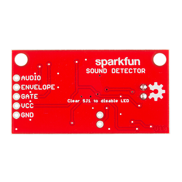
Good job on the board. Next board spin: check your gerbers and make sure all your silk is on the right layer for the parts. You are missing ref des'es everywhere and the solder jumper reference SJ11 doesn't match the note on the back. Works like a charm!
The only suggestion I would have, add pads for low pass filtering, band pass or high pass on the input.
We usually leave reference designators on the PCBs in layers that don't get printed in the silk.
The label on the SJ is an example of one reason we don't: the boards are fabricated and populated as a panel with many boards. Each instance on the panel takes the next set of unique sequential numbers. "SJ11" tells us it was the 11th board on the panel.
The label on the SJ has been fixed. The next batch of boards will all read as "SJ1."
The filtering is definitely an interesting idea, and I've been kicking a state-variable filter around on the workbench a bit. I'll keep it in mind!
Is this microphone the same as for the Breakout Board for Electret Microphone (BOB-09964) you sell?
(CEM-C9745JAD462P2.54R)
(100 - 10,000 KHz)
Yes. They both use the same capsule, and the preamplifier circuit of the Sound Detector is similar to the Electret Breakout. If you only used the audio output of the Sound Detector, it's similar to the electret breakout, the major difference being the gain.
Can anyone tell me what kind of current and voltage is coming out of the ENVELOPPE output please? I'd like to use it to drive the Violet LED (COM-12704) that is 30 mA and [3.0 - 3.6]V
Will that be ok right out of the box, or will I need something in between. (I plan on powering the Sound Detector with either standard rechargeable (1.2V) 4xAA batteries, or 3xAA (1.5V) premium alkaline)
Thanks!
I'd recommend a buffer in the application, perhaps with some additional gain.
Powering the circuit from 5.2V, and driving the mic until the audio output starts to clip, the envelope output swings from 0V to short peaks of maybe 3.25V. With a lower supply voltage, it won't swing quite so far.
There are several factors that make the violet LED a bit problematic.
So the output barely rises high enough to overcome the forward voltage, and when it does, there's only a trickle of current available.
Knowing that things were current limited like that, I just tried that violet LED to see what would happen. It flickers a tiny bit in response to the loudest sounds. In comparison, a plain red LED (Vfwd of around 1.8V) lights right up.
VERY USEFUL !!!! Thanks! (gotta love Sparkfun for that!)
So it looks like I should use 4x AA (1.2V) rechargeable batteries... =total of 4.8V. Unfortunately, 4xAA alkaline would be 4x1.5v = 6V, which is too much for the Sound Detector (Hookup Guide says max is 5.5V) Any other options for power source? It can't be much bigger that 4xAA, and can't be attached to a wall or computer (goes in a helmet)
Otherwise, here are the optional solutions I can see: (feel free to suggest more ideas...)
1) I could use a white LED with a purple screen in front of it, to achieve the desired effect. But... Should I go for a normal brightness white LED with a Vfwd as close to 2V as possible (which I'd have to order, but my time is limited), or, could I use this Super bright white LED that I have, which is Vfwd=[3.2 - 3.4]V and 20mA (18,000 MCD) ?? Update: upon a search on eBay and a few sites, this kind of low-voltage white LED seem very rare...
2) I have also purchased your "LED - Assorted (20 pack)" (COM-12062), which includes basic blue LEDs which were described by notexactly as: "Very bright at 9 mA (2.00 V over 220 Ω resistor)". If I find a suitable color screen to go in front of it, maybe that could also do the job... Would that likely react well if plugged straight on the ENV output? (with a resistor in between?)
3) I could modify the Sound Detector circuit by increasing the Gain (changing the R3/R17 value on the board as per the Hookup Guide) to try to get more signal out of this board... but not sure if it would give more V...
-.-.-.
Not sure how I would implement a buffer or additional gain for the LED though. Would I just put some Amp between the ENV output and the LED ? (I also purchased at the same time the Mono Audio Amp Breakout (BOB-11044) which is TPA2005D1-based, would that board work for that or is there a better board?)...
And by buffer you mean like a resistance between the Amp and the LED ? Sorry, I'm not an electrical engineer, just a hobbyist with a basic understanding of stuff and good learning skills. (which is why I love Sparkfun so much!!) So if anyone has pointers to similar applications and how-to's, please mention it!
Thanks!
I think the white LED will be similar to the Violet. The Vfwd and current ratings are pretty similar between them.
For the violet LED, the first thing I'd try is putting it on the Gate output, with a 330-Ohm resistor in series. That blinks very nicely on my workbench, from either 4.5V or 4.8V supplies.
Changing the gain set resistor will have more side effects than simply making the output signals stronger - it will also make the whole thing more sensitive to sound. If you increase it too much, it gets really touchy - cranked up too high, it triggers on quiet background sounds. In a noisy environment, it'd be on all the time.
A buffer would be a DC amplifier of some sort that would provide more current, and possibly increase the voltage. The mono amp breakout (BOB-11044) isn't suited to that, because it's AC-coupled, and the envelope output is DC voltage.
So please give the gate output a try first. I don't have a good recommendation for an easy to use buffer off the top of my head, but I'll ponder on it.
Lovely!!! Thanks again! Will do test the Gate and report, once I receive the stuff.
Interesting board! I'd very much like to use this along with an external audio source, but what's the max sampling rate one could achieve using this board connected to an Arduino's analogue pins? For my application 8kHz are the minimum required (need to perform an FFT after that), but is it achievable?
Are you hoping to sample at 8 kHz, or do you want the FFT to resolve frequencies including 8 kHz?
The Arduino documentation states (I believe they mean this for the AVR-based boards)
So you could sample at 8 kHz. however, to resolve 8 kHz, Nyquist's Theorem tells us you need to be sampling at more than double the highest frequency that you're trying to capture. The ADC isn't fast enough.
That also assumes that there is enough horsepower to run the FFT - they're computationally intensive. You'd probably have to do some work to allow the ADC to trigger a conversion-complete interrupt, so the FFT can run in parallel with the conversion. The Arduino library busy waits while the conversion is running.
An Arduino Due is probably a better candidate - it can sample more quickly, and the processor is much faster.
Thanks for your input!
I'm lucky in that I only work with frequencies up to ~4kHz. So the onboard 8kHz resolution (or 10k if we max it out :D ), is more than enough I suppose - which is great as I'd like to avoid having to use an external A/D.
In general, I'd like to keep everything as compact and energy efficient as possible, as I was hoping to develop something that can be deployed "in the field", running off battery and/or solar power. That's why I'd hesitate to grab the Due unless I find it's absolutely necessary - that and the relatively limited shield support and I/O voltage. [The same reasons make me lean towards Arduino instead of, say, a Beaglebone Black.]
Perhaps you're right re. performance; I've found a couple of FFT libraries for Arduino but I guess I'll have to "benchmark" them to be on the safe side.
I think I've looked over those FFT (and the corresponding FHT) libraries - one of them publishes a table that describes the time each operation takes, which is dependent on the sample size and number of bins. Higher resolution takes more time.
It's certainly not too hard to buffer a bunch of samples, take the FFT of them, then repeat. You'd be ignoring any input while the FFT ran, though. Getting a continuous, realtime FFT will involve some careful use of interrupts.
As an alternative to doing the FFT, you might look at the GSGEQ7 chip. It's a 7-band analog spectrum analyzer on a chip.
Thanks again, Byron.
I, too, am afraid real time FFT won't be feasible. Perhaps I can get away with the buffered approach, as the events I want to capture and FFT are not really continuous. I'm thinking I could use another sensor e.g. movement sensor or even an extra sound detector (so one with the stock mic and the other with my own external audio source). As soon as the stock board detects sound (using the binary indication already provided), it could trigger capturing from my custom audio source and then perform the FFT on the captured data. I just hope I can get enough samples in the buffer and hope there is no other trigger event while the FFT is running.
Btw, regarding the sampling rate, I just spotted this very interesting thread: http://forum.arduino.cc/index.php?PHPSESSID=01j0hofd57uh89v7tj0aq0t4v5&topic=6549.0
Seems you can sample much faster than 10k and without loss of resolution, just by appropriately tweaking the prescaler value!
Just in case it helps...
Using an Arduino Due with the prescalar value set as in that thread I'm able to sample every 10us (verified via oscope). That's plenty fast for the frequencies you're trying to capture.
Good luck!
Thanks - that's good to know! :))
hello..some questions about the envelope follower: what parts can be changed (if one have SMT soldering skills) in order to exploit the whole 5V/0V range if another source is used instead of the microphone (line audio, guitar, etc)? And in this case, we would need a over voltage protection to not exceed 5V? And what parts determine attack and decay times of the envelope?
The thinking on the gain staging was as follows: if the output from the preamp stage swung from rail to rail (0V to 5V), the rectifier then chops it in half. So the rectifier has a gain of 2.2, to restore the missing half. So rail-to-rail stays rail-to-rail there.
To use it with an external audio source, the recipe might be as follows
The opamp doesn't lock up when it clips, but it's not good practice to overdrive the input too significantly. You can protect the input by configuring a pair of diodes as a clamp.
The attack time is determined by R8. We want the circuit to be responsive, so it's pretty small at 100 Ohms. If it gets much bigger, it completely misses short bursts. The decay time is set by R9.
A number of guitar envelope followers are similar to this circuit - track down the Mutron 3, for instance.
Could these be used to measure extremely low frequency RF (<125 Hz) if the microphones were removed and an antenna added?
Looking at the schematic the trace to R1 would have to be cut. Other than that would these work to amplify the weak RF signal?
Hmmm...not an application that I anticipated, but I can see how it might be useful.
If you really do mean 125 Hz, I'd say it's worth a try. I have zero experience in that domain, but if you can induce a voltage into the first stage, this will work from roughly 16Hz to 12 kHz. If you want to extend the LF response, bump up the value of C2...you could even solder a "piggyback" cap right onto C2
However, if that's a typo for 125 kHz, this isn't going to work so well. The Amplifier has a rated gain-bandwidth-product of 1.2 MHz. When we ask it to do 100X gain, the bandwidth drops to 12 kHz, well below 125 kHz.
I am trying to measure RF between 40 - 125 Hz (not kHz). This looks like it would work...at $11 a shot its worth it.
Wow, this just looks like what I've been cobbling together.
Would it be possible to order these without the microphone? I'd like to run about 2 feet of wire from where I want the input noise to where the brains need to be (watertight enclosure)
we don't make these without the mic, but it adds a negligible cost, so you could just desolder it and attach your own wires.