- Home
- Product Categories
- Biometrics
- SparkFun Single Lead Heart Rate Monitor - AD8232

SparkFun Single Lead Heart Rate Monitor - AD8232
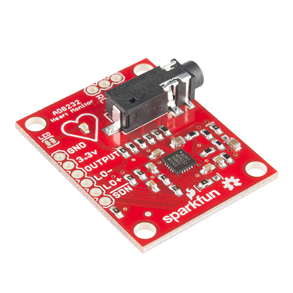
The AD8232 SparkFun Single Lead Heart Rate Monitor is a cost-effective board used to measure the electrical activity of the heart. This electrical activity can be charted as an ECG or Electrocardiogram and output as an analog reading. ECGs can be extremely noisy, the AD8232 Single Lead Heart Rate Monitor acts as an op amp to help obtain a clear signal from the PR and QT Intervals easily.
The AD8232 is an integrated signal conditioning block for ECG and other biopotential measurement applications. It is designed to extract, amplify, and filter small biopotential signals in the presence of noisy conditions, such as those created by motion or remote electrode placement.
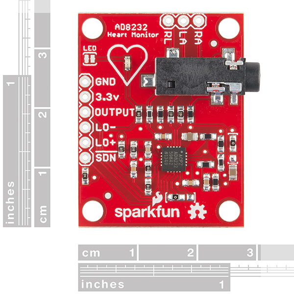
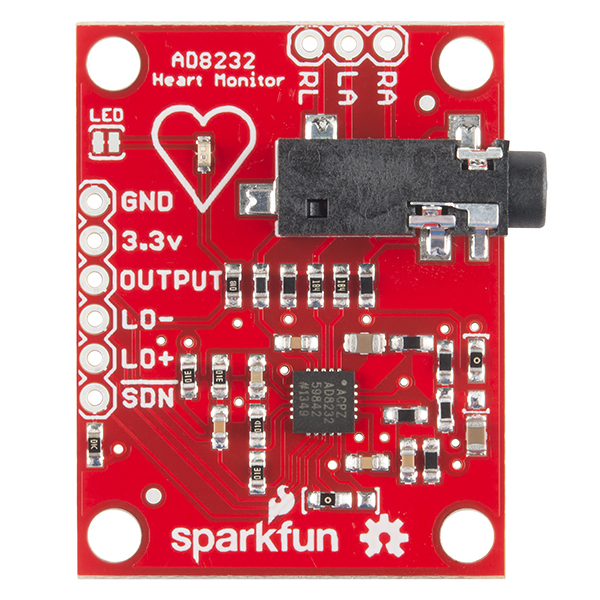
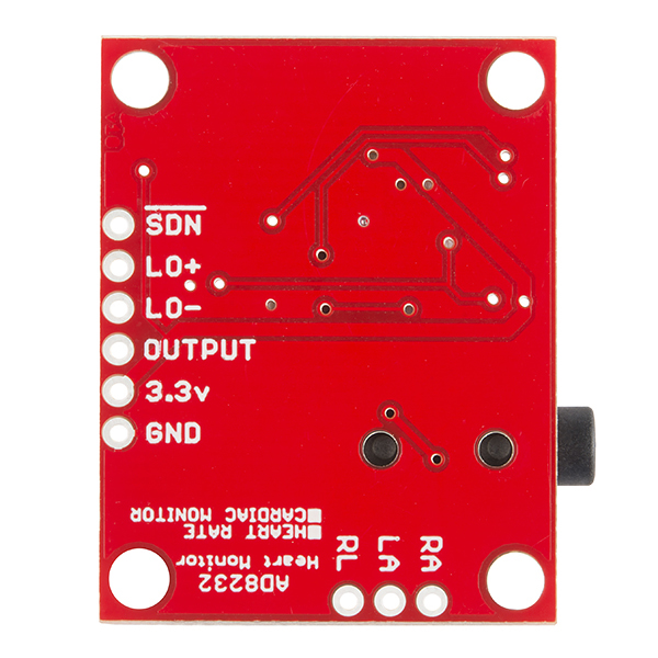
The AD8232 Heart Rate Monitor breaks out nine connections from the IC that you can solder pins, wires, or other connectors to. SDN, LO+, LO-, OUTPUT, 3.3V, GND provide essential pins for operating this monitor with an Arduino or other development board. Also provided on this board are RA (Right Arm), LA (Left Arm), and RL (Right Leg) pins to attach and use your own custom sensors. Additionally, there is an LED indicator light that will pulsate to the rhythm of a heart beat. Biomedical Sensor Pads and Sensor Cable are required to use the heart monitor and can be found in the Recommended Products section below.
Note: This product is NOT a medical device and is not intended to be used as such or as an accessory to such nor diagnose or treat any conditions. We recommend using the SparkFun Single Lead HRM with battery power to ensure no issues with a current loop when connected to the electrical grid. Additional protection can be provided via the SparkFun Opto-isolator Breakout if grid power must be used. Similar hookup recommendations can be found on the MyoWare Muscle Sensor via the user manual.
- Operating Voltage - 3.3V
- Analog Output
- Leads-Off Detection
- Shutdown Pin
- LED Indicator
- 3.5mm Jack for Biomedical Pad Connection
- Schematic
- Eagle Files
- Hookup Guide
- Datasheet (AD8232)
- GitHub (Design Files & Example Code)
- Product Video
SparkFun Single Lead Heart Rate Monitor - AD8232 Product Help and Resources
AD8232 Heart Rate Monitor Hookup Guide
July 17, 2014
Learn how to create your very own heart rate monitor.
0 of 1 found this helpful:
Electrodes are Single Use
If you are worried that something is not working on your project, verify these important checklist items:
1. Is the cable plug pushed all the way into the port?
2. Verify their power at the power pins is correct (eg +9V to +Vs, -9V to -Vs) - test with a multimeter.
3. Electrodes are not reusable.
Core Skill: Soldering
This skill defines how difficult the soldering is on a particular product. It might be a couple simple solder joints, or require special reflow tools.
Skill Level: Noob - Some basic soldering is required, but it is limited to a just a few pins, basic through-hole soldering, and couple (if any) polarized components. A basic soldering iron is all you should need.
See all skill levels
Core Skill: Programming
If a board needs code or communicates somehow, you're going to need to know how to program or interface with it. The programming skill is all about communication and code.
Skill Level: Competent - The toolchain for programming is a bit more complex and will examples may not be explicitly provided for you. You will be required to have a fundamental knowledge of programming and be required to provide your own code. You may need to modify existing libraries or code to work with your specific hardware. Sensor and hardware interfaces will be SPI or I2C.
See all skill levels
Core Skill: Electrical Prototyping
If it requires power, you need to know how much, what all the pins do, and how to hook it up. You may need to reference datasheets, schematics, and know the ins and outs of electronics.
Skill Level: Competent - You will be required to reference a datasheet or schematic to know how to use a component. Your knowledge of a datasheet will only require basic features like power requirements, pinouts, or communications type. Also, you may need a power supply that?s greater than 12V or more than 1A worth of current.
See all skill levels
Comments
Looking for answers to technical questions?
We welcome your comments and suggestions below. However, if you are looking for solutions to technical questions please see our Technical Assistance page.
Customer Reviews
4.1 out of 5
Based on 22 ratings:
1 of 1 found this helpful:
Устройство действительно работает!
Устройство работает устойчиво и качественно.. Схема взята из примера в руководстве на применяемый чип. Считаю, что для начинающих исследователей не самый удачный вариант схемного решения - По умолчанию используется трехэлектродная схема. Переделал на двух электродную - Очень широкая полоса пропускания фильтра. Значительный уровень помех от сети 50Гц. Требуется сдвинуть частоту ФНЧ до 20Гц. В целом лучшее из дешевых усилителей кардиосигнала.
Providing a translation :)
"The device really works!
The device operates stably and efficiently .. The circuit is taken from the example in the manual on used chip. I think that for young researchers is not the best option circuitry - The default is three-electrode circuit. Redid two electrode - Very wide bandwidth filter. A significant level of interference from 50Hz. Need to shift the frequency of low-pass filter to 20Hz. In general, the best of cheap amplifiers cardio."
1 of 1 found this helpful:
Poor Signal-to-Noise (SNR) ratio
I was using an Olimex ECG Shield which is a full-size shield for Arduino Uno (or equivalent) and wanted something that took up less room. The SparkFun AD8232 is about 1/3 the footprint of the Olimex.
The SNR on the Olimex is about 10x better. The AD8232 produces a usable ECG signal only if the subject sits very still, it's powered by a battery, and the LO+ and LO- lines are left disconnected to further reduce noise sources. Not adequate for my purposes.
One other thing, you'll need to use Processing 2.0 for the display. The sample sketch does a no-no in that it draws lines to the display from a Serial Event thread and Processing requires drawing operations be done from the Animation thread. Processing 3.0 enforces thread safety.
1 of 1 found this helpful:
Decent little board
Does what it claims. Some advice for hookup. Power with a clean supply (battery) not off your Arduino, this will clean up some noise. Don't just flop the led-cables across your desk, they can pick up noise from USB cables etc. If your using a 3.3v/8MHz Arduino, the stock ADC sampling frequency will struggle to catch all the QRS waves. You will need to either fiddle with the ADC sample rate, or the simpler solution is use the 5V/16MHz version instead. I have experienced a lockup with this board if I'm moving the leads while powered, just reads ~512, to fix turn off/unplug the 3.3V and ground the whole board by putting your thumb on top. Not elegant but it works. Comes right back after resupplying power.
7 of 7 found this helpful:
Nice design but beware of ESD
I was experiencing heart palpitations so I thought I would try this product out and do some self diagnosis. I hooked it up to an Arduino nano. Since my symptoms occur mostly at night I hooked myself up when I awoke at midnight in bed and immediately fried the first unit I bought, evidently by ESD from static generated by my bedsheets. You might beware of the potential for ESD and discharge yourself to ground before hooking yourself up with this product.
So, after buying a replacement unit I successfully got traces of my heart events. I matched my EKG waveform to traces I found online and guessed that my symptoms were caused by Premature Ventricular Contractions (PVC) which typically has onset in men my age. My self diagnosis was later confirmed by a cardiologist after reading data from a clinic provided 24 hour Holter monitor.
1 of 1 found this helpful:
Great But Bad Pinout
This ECG monitor is just about the easiest that I've come across and I'm happy with it. It will work with my project. However, The pinout on the audio jack is wank. The RA and LA connections should be wired to the R and L channels on the jack, and the RL should be wired to the GND.
If you could rev this board and make those connections it would be alot easier for folks to just plug on in with their cable splitters and have a good day!
1 of 1 found this helpful:
Great piece of hardware
Pros: 1. I was able to get readings from a sleuth of Arduino 8 bit, 32 bit, TI Launchpad 32 bit without any problems 2. The readings are quite consistent 3. Very compact design
Cons: 1. The 3.5 mm jack is not that great 2. There's noise that cannot be filtered easily - a good curve fitting algorithm will do the trick
Overall, great.
Worth the set up!
Took a while to setup (not to mention, this is my first time using Processing). Once I figured out how to run everything, it works great!
On a side note: use Processing 2.2.1 for the sample code.
HR monitor works nice, but SNR was bad. How can I adopt HR monitor to 50 Hz noise?
It actually works! for hobby purposes.
Hooked it up to an UNO, using 3.3V to power this module of course. Used fresh EEG electrodes - Silver-Silver-Chloride - same as EMG but not EEG - necessary for monitoring around 0.5 to 2HZ. Using Arduino Serial Plotter I get a nice QRS. Unfortunately there is so much noise in the signal, lots of 60HZ mains and lower amplitude just noise, so you'll have to do some notch filtering at least, and FFT or other software signal conditioning to get a clean readout. But this is a lot better than fooling with op amps.
Works well, came without header pins
I really like the price and functionality of this item, however assumed it would come with header pins (or at least emphasize that it did not/suggest to buy with them). It was a bummer when it came without them.
Other than that, highly recommend!
Works very well
I've looked at DIY heart monitor circuits before but with the microvoltages involved it would have been a major project to prototype my own. This works great - compact with the noise reducing bypass caps all in place. Running it off a 9V battery through a L78L33 regulator and viewing the output on an inexpensive $25 digital oscilloscope kit from eBay for display. It gets boring really quick, but it's a fun science project and would be great for classroom demos. Oh, and you can buy the adhesive sensor pads in bulk really cheap elsewhere.
Works great!
Fantastic value and great functionality. Signal was very clean too
It worked as advertised, however...
I paired the AD8232 to an arduino as described by this site. I downloaded the arduino code and made the connections as described. I attached the electrodes to my body and actually had EKG heart rate display on the arduino serial plotter. It worked exactly as described.
It was my first arduino project and I was quite pleased with the results.
However, my ultimate purpose for the device was to connect it to my elliptical exercise machine and have the heart rate collected from the metal handles on the machine. I have built raspberry pi to take over the controls of the elliptical and record distance and resistance of the machine. I also wanted to gather heart rate information as well. But so far I have not been able to find a circuit that would work to gather heart rate just by grabbing the handles of the elliptical as the original controller would.
When used in this manner, no heart rate is displayed and the data sent by the arduino is just hash.
As I said, when the it is used with the electrodes connected to the body, it works completely as advertised.
Overall I was extremely pleased with SparkFun's information and their shipment to me was quick and correct. I expect to order other projects from SparkFun as I continue to build projects.
Thank you!
Good functional unit
Some advice into how to clean up the signal would be welcome - like making sure the power is quiet - No switchers without ample capacitance to ground the ripple. A ground plane that is accessible would also be helpful It does require shielding the cable. I would recommend some instructions on how to shield it, and also how to protect it from ESD and also from defibrillators.
thanks.
Reliable reading and Easy to use
Very reliable and easy to use plug n play module. Best is class Single Lead Heart Rate Monitor available in the market.
Very cool board!
I developed atrial fibrulation last November and have been in a permanent afib state since then. This board and project gave me my first opportunity to work with the Processing application for Windows. Works like a charm, gives a recognizable EKG when wired as directed and clearly indicates my particular condition. Working on controlling or reversing the afib under my cardiologist's care, but it's fun to make and use an actual tool for viewing the data.
Very Good Product
By using this product We are able to monitor very accurate heart rate. Check our developed final product : OBD ii Connector is an electronic device used by car manufacturers to communicate with the vehicle’s computer system.
Name: OBD Cable OBD Scanner for bike Car OBD2 OBD ii obd scanner for car OBD Device OBD Port Link : https://www.mapout24.com/product-category/obd-diagnostic-cables/ Link: https://www.mapout24.com/product-category/gps-for-bike-car-truck-bus/ Link: https://www.mapout24.com/product-category/gps-locator-person-tracker/
Nice...
I used this, and the demo code, to build a wearable EKG display. Because the TFT I used took so many oins, I used an Arduino Mega 2560. Sadly, I ordered what looked to be the same device online but neither unit would work. I will stick to Sparkfun in the future for these.
Works great with UNO - Need with RAspberry Pi or Beaglebone Black
Working GREAT with UNO and Windows PC as described in the sample code.
This is a great product
This is an amazing device, and it is very complete. It might last like 5 seconds to stabilize, but after that, is really good. The bandwith is too big, I don't like this, because any movement makes noise because of the muscle signal, it goes all the wat to 1k Hz, and a normal ECG doesn't goes more than 250.
0 of 1 found this helpful:
I couldn't watch the heart rate using LA and RA
I tried to get a trigger from my heart rate in order to sincronyze s Scope but didn't receive nothing in the Output, neither couldn't see the red Led beating. Pls. Send to me some advice. THIS IS NOT A COMPLAINT!
Hi, We'll be happy to see if we can help you. Please submit your question to our technical support team here - https://www.sparkfun.com/technical_assistance
I keep getting a very deep Q wave. How do I fix this issue? Can provide pictures if needed
SparkFun Single Lead Heart Rate Monitor.
How would I get this kit to output to a small LCD or TFT screen without the use of a PC?
Hi there, it sounds like you are looking for technical assistance. Please use the link in the banner above, to get started with posting a topic in our forums. Our technical support team will do their best to assist you.
That being said, if you follow the hookup guide for this sensor, you will notice that you need a microcontroller to interface with it. You will then need to find a screen that your microcontroller can interface with and modify the example code appropriately for the screen to display the data.
(*You will still need a PC to do all the programming for the microcontroller/)
I added the saveFrame("heart.jpg"); // saves previous frame must stop the program after the frame you want in the processing Heart_rate_display code. It saves the screen to a jpg file at the end of every screen. Then stop the program on the next screen. See below. You can save every screen if you want, see : https://processing.org/reference/saveFrame_.html
// at the edge of the screen, go back to the beginning: if (xPos >= width) { saveFrame("heart.jpg"); // saves previous frame must stop the program after the frame you want xPos = 0; background(0xff);
How do you guys get over the whole danger of people thinking this is a medical device? Is the "Note" at the bottom enough? I also noticed there was no "battery-powered only" warnings.
Hello, I've been many problems with the code in Processing, please help me;
the error is this: ArrayIndexOutOfBoundsException:3.
P.S. My arduino Uno is COM3. I've tried many ways to solve my problem but I Didn't get it.
this is my code:
import processing.serial.*;
Serial myPort; // The serial port
int xPos = 1; // horizontal position of the graph
float height_old = 0;
float height_new = 0;
float inByte = 0;
void setup () {
// set the window size:
size(1000, 400);
// List all the available serial ports
println(Serial.list()); // Open whatever port is the one you're using.
myPort = new Serial(this, Serial.list()[3], 9600);
// don't generate a serialEvent() unless you get a newline character:
myPort.bufferUntil('\n');
// set inital background:
background(0xff);
}
void draw () {
// everything happens in the serialEvent()
}
void serialEvent (Serial myPort) {
// get the ASCII string:
String inString = myPort.readStringUntil('\n');
if (inString != null) {
}
}
The values which we get from AD8232 are as follows: 483 481 480 485 492 501... What are these values ? Are these voltages or what?
Hello everyone. Can this sensor measure also the muscolar contraction?
Thank you all!
Hi i am trying to send the ECG signal via wireless to the PC to processing(maybe). Is there.
i use arduino uno. My all connections are true. I always get square wave. Please help.
I cant understand what is reason this?
any ideas on how to filter the noise for movements? I'm trying to do a heart rate monitor for running using chest straps (like a polar). but I'm not able to filter the noise.... any advises would be great
Hello,
I am trying to do something similar. Perhaps we could help each other out. PM me to fieryfire@gmail.com
Hi
I have recently purchased the board, however, even the standard examples do not work for some reason! I get always something like this in my serial monitor (sketch from the example was used):
697 698 697 ! 696 697 698 ! 698 698 ! 697
Moreover, the LED which is supposed to indicate heart beat is not blinking and it is always red! The only difference in my setup is that I have connect the board to the A2 analog pin. I have also soldered male pins to the board (LA, RA, LR).
Am I doing something wrong? Has anyone faced similar problem with this product? Can it be so, that those soldered extra pins affect on the functioning of AD 8232?
Hi,
have you tried using processing for the output. you may have to use another program called processing that draws out the signal for you.
Was trying this with multiple Arduino boards and was happy to know that it works on all! However, the signal I had a problem. The T part of the wave has the same amplitude as the R peak, is there anything I can do to remedy this problem? I tried it with a few of my friends too and the results are all the same.
Can I use the monitor with an Arduino Yun? Coz I am working on a wireless ECG monitor and other similar projects. Please reply me the advantages and drawbacks of using this with an yun..
I see no difference between using this with the Yun vs the Leonardo or Uno. The biggest issue will be that this board run at 3.3V and not 5V. Since all the I/O pins on the Arduino seem to be inputs you won't be sending 5V to the board, so just make sure you are powering it correctly and it should work fine.
does this heart rate monitor sensor board, leads and the cable follow any industrial standard (e.g., http://www.fda.gov/MedicalDevices/DeviceRegulationandGuidance/GuidanceDocuments/ucm073942.htm#14_3) during the design, manufacture and post manufacture quality test? how safe is it to connect to a human body directly following your hookup guide? is there any known potential risk when applied to human?
We followed all precautions outlined in the datasheets. Our internal testing procedures look for circuit faults, manufacturing defects, and general functionality. Following the hookup guide I had one stuck to me for a few hours in various spots (looking for ideal placement of sensor pads). Since this is more of a demonstration board and less of a medical device, we can't offer the same guarantee as a medical device company. As our disclaimer states: This product is NOT a medical device and is not intended to be used as such or as an accessory to such nor diagnose or treat any conditions. Let me know if this answers your question.
Hello Casey,
Could you please tell me the modification i can make in the Arduino codes, to send the ECG wirelessly to the PC or perhaps a way to communicate and ECG using two arduinos and then print it to processing.
CaseyTheRobot, thanks for the reply! I read and understand the disclaimer statement of your website. But for a hobbyist or a student that use or plan to use this this heart rate monitor in their biomedical exploration, what is the safety guidance for them if they hook up on their own bodies? I understand the required supply voltage of the sensor is pretty low. but how do you ensure the electrical current flow through the electrodes near the human heart is always low within safety range? For example, can this device be safely used in a university classroom on students for teaching and learning purpose?
I just looked over the schematic and the resistors being used are pretty big (between 180k and 10Mohm). These are to help isolate the person from the circuit. However, it is VERY IMPORTANT to use a completely isolated circuit. In short, do not attach this in any way to anything plugged into a wall outlet. This must remain battery operated for safety reasons. If you need to get serial data from the MCU then you are stuck either doing it wireless or through USB/serial on a laptop that IS NOT plugged into a wall or Ethernet cable.
Hi! Would you recommend this device for measuring biosignals from plants?
Has anyone used this ECG board with two leads/electrodes? The reason I ask is because I see an error in the schematic. R18, which is not installed for 3-lead configuration, should go to RLD and not to SW. Refer to fig 62 on page 24 of the AD8232 datasheets.
Best Regards
How difficult would it be to have the rate be displayed on a 16x2 LCD ?
Does anyone know if I can use Arduino Uno ?
The code should work with an UNO
This works great for me!
However, I ordered my own PCB that was identical to yours (I copied the eagle brd file) and tried populating it myself and it didn't work..
I've tried both reflow and hand soldering and neither method has produced a working board for me.
Do you have documentation on how you populate your boards? Did you run into any similar problems when first working with this IC?
The only special consideration we have taken was with the GND pad of the AD8232. We reduced the solder paste size greatly because we found the chip floating and making bad connections. Try reducing or removing the solder from the GND pad.
How are you soldering it? This chip's max temperature rating is 140 C. At that temperature most solder pastes will only start melting... and the max rating is only for a few seconds! You will need a special service to solder it I think, I have been trying to do something similar unsuccesfully... But I am looking for a service that would solder components on one or two boards... Not requiring at least 100 boards min
Hi,
I've been trying to get a proper output of this board, and all I get is a square wave ranging from 200+ to 800+... does anyone know why this may be? I'm setting !SDN to 3.3V since I'm not using the functionality to turn off and on... and I set AC/!DC to GND that's the only difference I did...
Thanks in advance for the help
If you are using our breakout, the !SDN is tied to 3.3v by default. The AC/!DC line is tied to ground by default as well. The square wave you are seeing is the "Lead Off" Detection. You may need newer sensor pads if all three are not making good contact with skin.
Hello i also get a square wave. My all connections are true. Please help me ?
I'm using 3 boards, 2 are yours one is mine, one of yours and mine give me the square output wave, the other one from you gives me a good ecg signal...
Also, the leads off detection should only display a flat lined output at half or almost the potential, which it does on the good sf board, but I can't get to seem to get an ecg waveform at all from one sf board or mine... And this output is quite intriguing me..... I want to say emi but why on two only and not the other?
with operating voltage at 3.3V, what is the analog output range of this Single Lead Heart Rate Monitor - AD8232 (0-1.5V)?
0-3.3V
thanks! after carefully read the AD8232 data sheet. I derived the range similar as your answer. According to the data sheet, the voltage at the analog output terminal (OUT) swings in between 0.1 Volts and Vs – 0.1 Volts, where Vs is the supply voltage. If using 3.3 Volts as Vs, the output range is 0.1 – 3.2V.
Have connected this to a Arduino pro mini 328 and that in turn connects to a Raspberry Pi to run the processing. Both the Pro Mini and AD8232 run off of the 3.3v GPIO, whilst I get a good trace I also pick up 50hz (UK) noise and although adding a few caps diminishes it is still quite noticeable.
Any thoughts of how to lower the noise? For example would it be good to run the Arduino and AD8232 from their own 3.3v regulators and have these use caps to lower the noise also? Any help would be appreciated as the pro mini 3.3v 328 & Pi make a great combination.
I reduced the noise by giving each component a 3.3v through a regulator off of the 5v Pi line and also moving things around so that the 3 sensor leads didn't come near or cross any other signal or power traces.
Oversampling also reduced the noise.
Any idea the difficulty to solder this with the SparkFun hot air rework station? Also the actual or best temperature to warm the hot air rework station at? I know I should look at the datasheet, but anyone got any first hand experience? sometimes real-life experience works better than datasheets... and these chips don't grow on trees :)...
thanks
Are you planning to remove the IC from the board?
No, I was planning on playing around with the IC on other applications since it's an instrumentation amplifier and its tiny, and it's not bipolar! See the possibilities there? I bought a bunch of them and printed a breakout board for these tests! I'm just wondering how I should proceed to solder it....
Well... I almost succeeded on my first try.... I'm only making ONE short circuit... damn... I gotta re-try it again... its so hard even being ambidextrous to control both the 500x microscope and the hot air rework station and without a helping hand... and no components/local stores are near me to buy one asap.... hmmm... gotta unsolder it and try again I guess... its funny how the packaging of the AD8232 says you have 164 hours from when you open the package to solder the pieces otherwise you'll need to oven them first... I guess humidity does play a big factor...
Try turning down the air flow, sounds like you are blowing the chip off the board. lots of flux and don't add much solder to the ground pad, without a stencil and paste, it can be tricky. you should be able to melt the solder and use surface tension (and a nice toothpick or tweezer end) to poke the chip in place. Good luck!
Thanks! I got the air flow at 3 it wasn't really blowing, I did put a bit too much solder that was what I did wrong! it just squeezed on to the pads but as it squeezed solder started flowing out and making contacts lol... will try again tomorrow but wondering whether the flux will reach the gnd pad? or I should try a different IC and PCB... hate wasting...
Thanks again for the response!
I plan to use this without a micro-controller. Any suggestions on how to power this? What is the voltage range it will actually accept, still function and not burn? Is 3.3V a hard upper limit or will it accept 5V or 9V? What about in the other direction, like 3.0V from a coin battery or 2xAA betteries?
In the tutorial, the pin connection table shows LO- is connected to Pin 11 on arduino and LO+ is connected to Pin 10. However, on the connection diagram graph, LO- is not connected to arduino and LO+ is connected to Pin 11 in green wire. ??
can i connect the pads to the wrist? or do the 3 pads have to be connected at the heart area?
Can connect to wrists, arms... any connection that has a current path across the heart will give you a signal
Great little module: Works as advertised with sample code. Thanks!
Added a few lines to Casey's excellent processing code to give multiline, 200ms tick marks, and screenshotting
Is it electrically isolated from the power supply?
The leads are not 100% isolated from VCC. There are 180k ohm resistors in series with each lead. This is aimed to prevent any stray high currents.
you can simply add some diodes to the connection (granted you'd have to make your board) to prevent feedback current
Diodes would block the low voltages produced by muscle contractions.
Yes, realized my mistake after..... Diodes voltage suckers..... Ha ha! Sorry brain fart!
When I followed the tutorial to try it, the plot is upside down. Any idea?
Are you sure you don't have the RA and LA electrodes backwards on your chest?
Why does this use RL (right leg) i stead of the commonly used LL (left leg) for 3lead ECG
That was pointed out by a med school friend of mine as well. I tried reading into it and didn't get far. I didn't know there was a prefered placement until it was pointed out.
Both are acceptable methods of electrode placement, this is because they both generate a relative signal reference to either left arm or right arm, you could also place the leg electrode on the right elbow or left elbow and this would still be acceptable. In a left leg electrode, It is used to monitor the voltage between the right arm electrode and the left leg electrode... similarly the other way around...
hey!.... the last answer is 38 minutes and 20 seconds.... Awsome video! I love you SparkFun. Thank you Robert to be on time every friday. You make me dream, thanks a bunch!
If my calculations are correct, the Cut-off frequency of this device is at or around 41Hz.... I'm just wondering if that seems a bit low? or I guess since its within the 0.5 - 150 Hz range shouldn't matter? Smart... then you remove most of the 60 Hz signal noise
Although "clinical" grade ecgs are sampled up to 250 Hz sometimes, the majority of useful data is less than 25 Hz. LPF @41 Hz will give you a recognizable ecg signal
The github repo doesn't appear to exist!
Try again? I think it got switched to private by accident.
Works now, thanks!
The eagle files link takes us to the schematic, and the github link to a 404 website. Just letting you know, in case you can modify this.
Thanks
It should be fixed now.
Confirmed, Thanks a lot!
On the Connecting the Hardware page of the tutorial for this, it says: "The four pins you need are labeled GND, 3.3v, OUTPUT, LO-, and LO+"
Um..., that be five pins, folks. :-)
Primary protection against electric shock is provided by the resistors in series with the arm and leg leads. SF should confirm that those resistors also are rated for >36V insulation resistance and that the clearances of the leads are sufficient for that voltage. Although SF customers are generally savvy, my rule for design of such devices is that they should not conduct even if an idiot user touches 120V and the device is earth-grounded.
Did you add the AD8232 and 3.5mm stereo jack to the SF eagle library?
The IC is in Sparkfun-AnalogIC.lbr The connector is in Sparkfun-Connectors.lbr
You might need to do a fresh "git pull" to update.
Sweet! Thanks!
yes! if it's a board we make, you will find all the parts in the eagle library by the time the product is listed on our site.
:)