- Home
- Product Categories
- 3-axis
- SparkFun Triple Axis Accelerometer Breakout - MMA8452Q


SparkFun Triple Axis Accelerometer Breakout - MMA8452Q
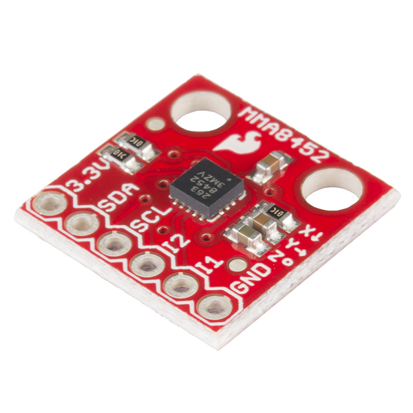
This breakout board makes it easy to use the tiny MMA8452Q accelerometer in your project. The MMA8452Q is a smart low-power, three-axis, capacitive MEMS accelerometer with 12 bits of resolution. This accelerometer is packed with embedded functions with flexible user programmable options, configurable to two interrupt pins. Embedded interrupt functions allow for overall power savings relieving the host processor from continuously polling data.
The MMA8452Q has user selectable full scales of ±2g/±4g/±8g with high pass filtered data as well as non filtered data available real-time. The device can be configured to generate inertial wake-up interrupt signals from any combination of the configurable embedded functions allowing the MMA8452Q to monitor events and remain in a low power mode during periods of inactivity.
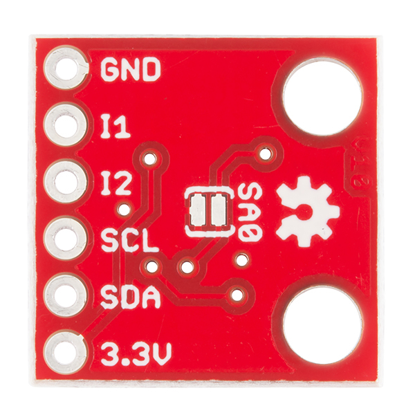
This board breaks out the ground, power, I2C and two external interrupt pins.
Note: If you are looking for the SparkFun Triple Axis Accelerometer Breakout with headers, it can be found here or in the Recommended Products below.
- 1.95 V to 3.6 V supply voltage
- 1.6 V to 3.6 V interface voltage
- ±2g/±4g/±8g dynamically selectable full-scale
- Output Data Rates (ODR) from 1.56 Hz to 800 Hz
- 12-bit and 8-bit digital output
- I2C digital output interface (operates to 2.25 MHz with 4.7 kΩ pullup)
- Two programmable interrupt pins for six interrupt sources
- Three embedded channels of motion detection
- Orientation (Portrait/Landscape) detection with set hysteresis
- High Pass Filter Data available real-time
- Current Consumption: 6 μA – 165 μA
- Schematic
- Eagle Files
- Hookup Guide
- Datasheet (MMA8452Q)
- GitHub (Design Files & Example Code)
- GitHub (Library)
SparkFun Triple Axis Accelerometer Breakout - MMA8452Q Product Help and Resources
SparkFun Inventor's Kit for Photon Experiment Guide
September 3, 2015
Dive into the world of the Internet of Things with the SparkFun Inventor's Kit for Photon.
Blynk Board Washer/Dryer Alarm
March 31, 2016
How to configure the Blynk Board and app to notify you when your washer or dryer is done shaking.
Qwiic Accelerometer (MMA8452Q) Hookup Guide
April 5, 2018
Freescale’s MMA8452Q is a smart, low-power, three-axis, capacitive micro-machined accelerometer with 12-bits of resolution. It’s perfect for any project that needs to sense orientation or motion. We’ve taken that accelerometer and stuck it on a Qwiic-Enabled breakout board to make interfacing with the tiny, QFN package a bit easier.
Library Compatibility with Other Arduino-based Boards
The library was designed for the Arduino UNO development board so there can be some issues with libraries if you are trying to port it to another microcontroller. If you see this error output when trying to upload to an ESP8266 through the Arduino IDE, this is due to the fact that the MMA8452Q's library is using a variable that is already used by the ESP8266 core:
Arduino: 1.6.4 (Windows 7), Board: "SparkFun ESP8266 Thing, 80 MHz, 115200, 4M (3M SPIFFS)"

In file included from SparkFun_MMA8452Q_Basic.ino:34:0:
C:\Users\bobby.chan\Documents\Arduino\libraries\SparkFun_MMA8452Q/SparkFun_MMA8452Q.h:32:11: error: 'STATUS' redeclared as different kind of symbol
STATUS = 0x00,
       ^
In file included from C:\Users\bobby.chan\AppData\Roaming\Arduino15\packages\SparkFun\hardware\esp8266\1.6.4-673-g8cd3697/tools/sdk/include/ets_sys.h:11:0,
             from C:\Users\bobby.chan\AppData\Roaming\Arduino15\packages\SparkFun\hardware\esp8266\1.6.4-673-g8cd3697\cores\esp8266/pgmspace.h:9,
             from C:\Users\bobby.chan\AppData\Roaming\Arduino15\packages\SparkFun\hardware\esp8266\1.6.4-673-g8cd3697\cores\esp8266/WString.h:29,
             from C:\Users\bobby.chan\AppData\Roaming\Arduino15\packages\SparkFun\hardware\esp8266\1.6.4-673-g8cd3697\cores\esp8266/Print.h:26,
             from C:\Users\bobby.chan\AppData\Roaming\Arduino15\packages\SparkFun\hardware\esp8266\1.6.4-673-g8cd3697\cores\esp8266/Stream.h:26,
             from C:\Users\bobby.chan\AppData\Roaming\Arduino15\packages\SparkFun\hardware\esp8266\1.6.4-673-g8cd3697\libraries\Wire/Wire.h:28,
             from SparkFun_MMA8452Q_Basic.ino:33:
C:\Users\bobby.chan\AppData\Roaming\Arduino15\packages\SparkFun\hardware\esp8266\1.6.4-673-g8cd3697/tools/sdk/include/c_types.h:58:3: error: previous declaration of 'typedef enum STATUS STATUS'
 } STATUS;
   ^
Error compiling.
Try modifying the MMA8452Q's library by changing the variable name with a text editor by :
changing STATUS to STATUS_M in the file SparkFun_MMA8452Q.cpp on line 95
changing STATUS to STATUS_M in the file SparkFun_MMA8452Q.h on line 32
Core Skill: Soldering
This skill defines how difficult the soldering is on a particular product. It might be a couple simple solder joints, or require special reflow tools.
Skill Level: Noob - Some basic soldering is required, but it is limited to a just a few pins, basic through-hole soldering, and couple (if any) polarized components. A basic soldering iron is all you should need.
See all skill levels
Core Skill: Programming
If a board needs code or communicates somehow, you're going to need to know how to program or interface with it. The programming skill is all about communication and code.
Skill Level: Competent - The toolchain for programming is a bit more complex and will examples may not be explicitly provided for you. You will be required to have a fundamental knowledge of programming and be required to provide your own code. You may need to modify existing libraries or code to work with your specific hardware. Sensor and hardware interfaces will be SPI or I2C.
See all skill levels
Core Skill: Electrical Prototyping
If it requires power, you need to know how much, what all the pins do, and how to hook it up. You may need to reference datasheets, schematics, and know the ins and outs of electronics.
Skill Level: Rookie - You may be required to know a bit more about the component, such as orientation, or how to hook it up, in addition to power requirements. You will need to understand polarized components.
See all skill levels
Comments
Looking for answers to technical questions?
We welcome your comments and suggestions below. However, if you are looking for solutions to technical questions please see our Technical Assistance page.
Customer Reviews
4.6 out of 5
Based on 10 ratings:
0 of 1 found this helpful:
still struggling with MMA8452Q
First, Sparkfun is amazing ! I use a PICAXE 14M2. I found some helpful code on PICAXE FORUM. But my HI2CIN instruction does not bring in data from my accelerometer. I have had good luck with I2C protocol until I tried this device for use with my QUAD and also another device T5403 barometric pressure sensor. But I have not given up on these while I'm pursuing other approaches for my experimental QUAD. Note that I bypass RC and speak to QUAD directly from my micro-controller.
This is awesome!
I love this device. I'm completing a security system within intrusion sensors based on this device, and I am quite impressed. There are many interrupt functions that allow this to be used in low-power battery applications. I'm currently using this with a Moteino, and when the circuit is asleep, the entire system consumes roughly 30uA! The accelerometer interrupts are what make this possible. For those interested, I've expanded on Sparkfun's library here:
https://github.com/mattmunee/MMA8452Q_Arduino_Library
It's a work in progress, but it now has code for using ALL of the interrupt functionality.
Works easily with the Teensy 3.1
I found that setup was easy, and the I2C connection worked out-of-the-box, with the example program. I found it easy to incorporate into my project. 10 minutes soldering to add the pins 20 minutes of software learning inside the Arduino/Teensyduino environment Done.
Works as expected!
Accelerometer works great!
Easy to use
Easy to find libs and code examples. Works as expected.
Breakout - Accelerometer Board
Received it in a timely fashion and it works great. Would not hesitate to buy anything else from SparkFun. Very satisfied.
Amazingly accurate accelerometer
I mounted this pin on a GPS shield with SD card recorder, then on to an Arduino Mega. The project measures how bumpy a tractor is, so we can go back in the spring and smooth out the rough spots.
It was working great, but then I accidentally dropped the enclosure everything was mounted in, and now it doesn't work. The GPS, SD, and Mega all work fine, but when the call for accel.init(SCALE_8G, ODR_6); gets called, everything freezes.
At least they are cheap enough that I can replace it without too much worry.
Works great
Great open source support. Dropped in code and everything just worked.
Exactly what I wanted
Worked perfectly out of the box. Actually code (running on STM32) worked the first time. Haven't implemented much of what the chip supports -- haven't used tap detection and haven't used portrait/landscape, etc. but the readings are solid and are consistent across (moderate) temperature swings. Love it.
Thanks Sparkfun!
I think the X and Y arrows are backwards? When it sits flat (Z pointing up), I get roughly +1 g on the Z axis (according to the MMA8542Q Arduino library's getCalculatedX functions). When I flip it so the Y arrow on the breakout board points up, Z goes to zero but Y goes to -1 g, not +1 g. Comparing the datasheet to the picture above, it also looks like X and Y are defined backwards.
Obviously the simplest thing in the world to correct for. It just took me a little head-scratching trying to figure out what I did wrong. I don't see any comments about it, though, so worth a double-check.
Where can I find the board specs (size, holes, etc) [Mechanical Drawings]
Can two of these be used on the same i2c bus?
Yes, they will need different addresses, but there is a jumper on the back of the board to change the address.
Hello, I'd like to use 2 of these with one Photon, I was looking in the build library and I can't quite see how to address them. Is this possible? Thank you.
Excellent.
FYI, the comment on the schematic that says SA0 = 0 by default is wrong. With the jumper open SA0 = 1, making the default address 0x1d.
I'm surprised that no one has mentioned this, but from the I2C module description in the datasheet (5.10.1):
Unfortunately it seems that BCM2835 (RaspberryPi's SoC) does not support repeated START sequence. This means that this accelerometer is not compatible with the I²C bus on RaspberryPi.
More information in the link here.
I am using the MMA8452Q Triple Axis Accelerometer Breakout on a breadboard circuit that is connected to a mini-Bully PIC24HJ64GP502 (no longer sold by Spark Fun) to detect motion of the board. As long as my MMA8452Q is situated in a horizontal plane when I download its code from the PIC24 microcontroller, it seems to work fine (i.e., the I1 pin outputs a 3.3 volt signal when the breadboard is moved, and it outputs zero volts when motionless). However, if the MMA8452Q is not situated in a horizontal plane during downloading of its code, it does not function appropriately (i.e., the I1 pin constantly outputs 3.3 volts whether there is motion of the breadboard or not). This is important because my application circuit will eventually be connected to my wrist when first activated, and then worn throughout the night while I sleep (I just need to know when motion occurs, not any of the characteristics of the motion).
I have set the MMA8452Q's registers thus:
write2I2C1(MMA8452Q_ADDR, FF_MT_CFG, 0x78); // ELE=0, OAE=1, ZEFE=1, YEFE=1, XEFE=1 write2I2C1(MMA8452Q_ADDR, FF_MT_THS, 0x8F); // DBCNTM=1, THS[6:0]=15 threshold=(15)x(0.063g)=0.945g write2I2C1(MMA8452Q_ADDR, FF_MT_COUNT, 0xFF); // 0xFF=255(decimal), ODR=800Hz, debounce time=(1.25/1000)x(255)=0.319 second write2I2C1(MMA8452Q_ADDR, CTRL_REG1, 0x04); // ODR=800HZ, LNOISE=1, F_READ=0, ACTIVE=0 (STANDBY mode) write2I2C1(MMA8452Q_ADDR, CTRL_REG2, 0x00); // disable SELF TEST, disable RESET, OVERSAMPLING MODE (Normal), disable auto-SLEEP write2I2C1(MMA8452Q_ADDR, CTRL_REG3, 0x08); // enable FF_MT wake up, IPOL=0(interrupt polarity=active low), enable PUSH PULL write2I2C1(MMA8452Q_ADDR, CTRL_REG4, 0x04); // disable auto SLEEP/WAKE interrupt, enable FF_MT interrupt write2I2C1(MMA8452Q_ADDR, CTRL_REG5, 0x04); // FF_MT interrupt output signal assigned to INT1 pin of MMA8452Q write2I2C1(MMA8452Q_ADDR, CTRL_REG1, 0x05); // now place MMA8452Q (accelerometer) in ACTIVE mode to detect motion
Can anyone advise me as to how to get the MMA8452Q to work properly no matter its spatial orientation when initially programmed by the microcontroller?
Thanks
Hi, I just two two of this module and it work well, so I was looking at the datasheet and it got no way recommended layout footprint for this component MMA8452Q. Could you share the library of this component for me or any recommended layout footprint?
Does the Breakout Board come with the MMA8452Q Accelerometer already soldered to it? Or do I need to purchase the accelerometer along with the board?
It comes with it soldered on it. We make it explicitly clear if the sensor is not included on the breakout board.
What is the purpose of I1 and I2? Interupting the board to send data? Seems strange if you need repeated START'S to read the data...
Where is the sketch located from the simple sketch video above?
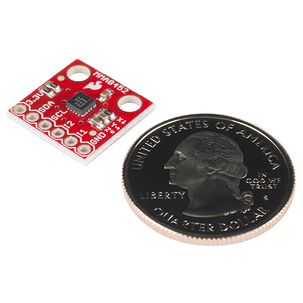
What are the dimensions of this board? I can't seem to find it on the page or in any of the included documents.
The board is 0.60 x 0.60 inches. If you need more component-specific dimensions, you can load up the Eagle Files with the free version of Eagle, and measure around in there.
What is the difference between this and SEN-10955? https://www.sparkfun.com/products/10955
The component footprints got larger for easier QC. It's a hard to see change small but if you open two tabs and click between them you'll see the footprints got larger. We used to use a very tight footprint for our 0603 parts. This worked great for years but as our production got more complex we needed AOI (automated optical inspection). For the best possible testing we increased the footprints so that the AOI could see and rate a full solder fillet.
That's really cool. I'll take a slightly larger footprint as a trade for good automated QA inspection.