- Home
- Product Categories
- Solar Chargers
- SparkFun Sunny Buddy - MPPT Solar Charger

SparkFun Sunny Buddy - MPPT Solar Charger
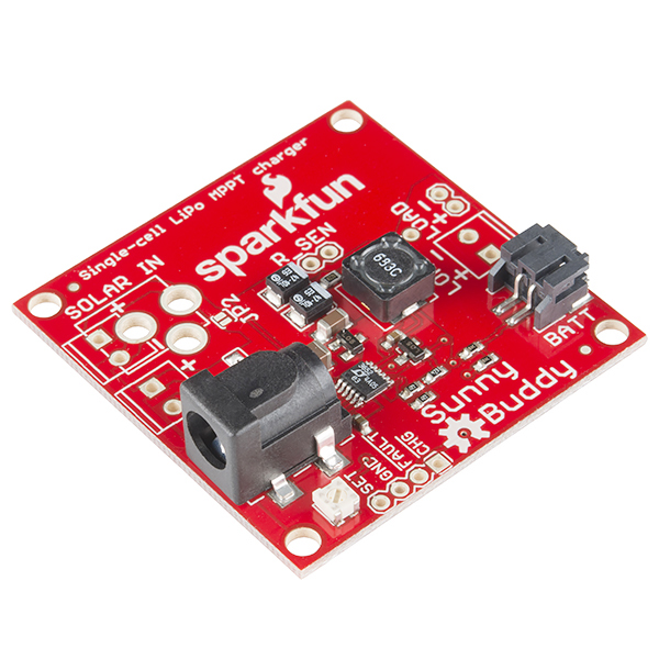
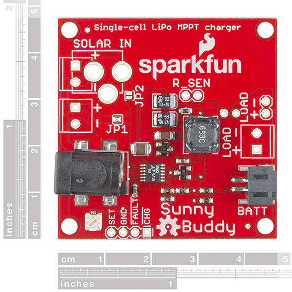
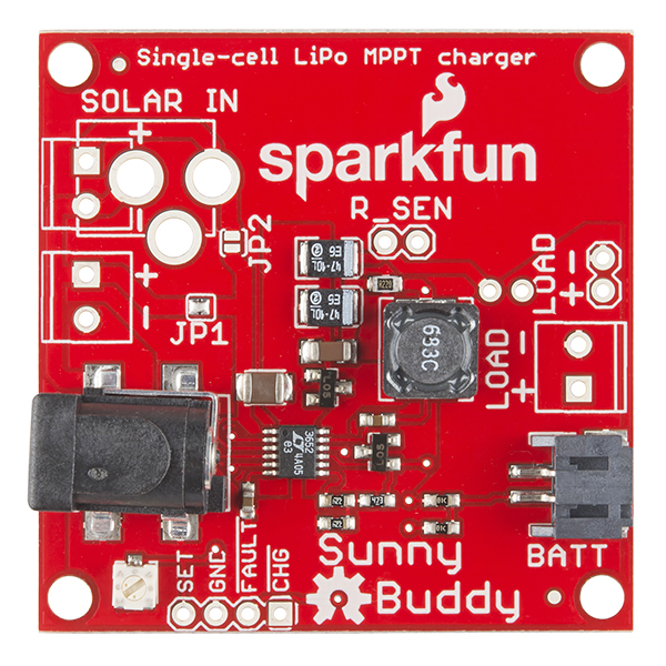
This is the Sunny Buddy, a maximum power point tracking (MPPT) solar charger for single-cell LiPo batteries. This MPPT solar charger provide you with the ability to get the most possible power out of your solar panel or other photovoltaic device and into a rechargable LiPo battery. Set-up is easy as well, just plug your solar panel into one side of the Sunny Buddy and your battery into the other and you are good to start charging!
The output of the Sunny Buddy is intended to charge a single polymer lithium ion cell. The load should be connected in parallel with the battery. By default, the Sunny Buddy comes set to a maximum charge current of 450mA with a maximum recommended input of 20V (minimum 6V). It’s recommended that batteries not be charged at greater than their capacity rating; thus, the smallest battery that should be charged with the Sunny Buddy is 450mAh.
Each Sunny Buddy comes equipped with a LT3652 power tracking 2A battery charging circuit and pre-installed barrel jack and 2-pin JST connectors with unpopulated areas to install your own personal 3.5mm screw terminals for added input/output options. This revision also adds a potentiometer to the input to set the holding voltage for MPPT and we've also tweeked the feedback resistors on the output to change the float voltage.
- Schematic
- Eagle Files
- Datasheet (LT3652)
- Hookup Guide
- Weather Station Tutorial
- GitHub (Design Files)
SparkFun Sunny Buddy - MPPT Solar Charger Product Help and Resources
IoT Industrial Scale
October 10, 2016
What does a baby elephant weigh? How much impact force does a jump have? Answer these questions and more by building your very own IoT industrial scale using the SparkFun OpenScale.
Sunny Buddy Solar Charger V13 Hookup Guide
October 13, 2014
How to hookup the Sunny Buddy: a solar-powered, MPPT (peak-power tracking), LiPo battery charger.
Core Skill: Electrical Prototyping
If it requires power, you need to know how much, what all the pins do, and how to hook it up. You may need to reference datasheets, schematics, and know the ins and outs of electronics.
Skill Level: Competent - You will be required to reference a datasheet or schematic to know how to use a component. Your knowledge of a datasheet will only require basic features like power requirements, pinouts, or communications type. Also, you may need a power supply that?s greater than 12V or more than 1A worth of current.
See all skill levels
Comments
Looking for answers to technical questions?
We welcome your comments and suggestions below. However, if you are looking for solutions to technical questions please see our Technical Assistance page.
Customer Reviews
4.2 out of 5
Based on 10 ratings:
9 of 9 found this helpful:
Neat board, works well.
I originally bought this for a project specifically running off solar, but I knew I was going to make multiple ones, so cost is a bigger factor than just a one-off.
I had to read up on various charging methodologies and how they impact charging speed & battery longevity.
On the surface MPPT seemed perfect, but after doing a few sample runs, I settled on a non-mppt solution.
Did this board work? Absolutely.
Did this board work well? Absolutely.
Would you recommend this board? For someone needing MPPT charging, Yes.
The board I bought is in service, and doing it's job, and doing it well. I wish it had some better monitoring on-board. (ie: battery status).
If you're building one unit and need to pick a charger, this is a great choice, if you're looking to build a bunch where price can add up; mppt might not be the cure-all. Personally, I like the rocketscream boards for when solar charging is needed.
4 of 4 found this helpful:
Neat little board!
I bought this board to use with the Large Solar Panel from this site. It's been really interesting to experiment with. The flexibility of the footprints on the board is really nice because it allowed me to attach terminal blocks to the inputs so I could connect the panel voltage to one and a current sensor to the other. Great!
One suggestion for this board: consider adding an independent voltage input to the set pin so that the MPPT can be managed by a controller.
4 of 4 found this helpful:
Keeps output below 4v, but I wish the NTC pin went somewhere...
This charger was great for me - one feature not described in many chargers is whether the charger will always output 3 volts even if the solar panel voltage goes above that. I tried a few other chips which all listed passing through the panel voltage as a feature. This is actually big design annoyance for 3v devices. However, the sunny buddy will always output max 4v even without the battery plugged in, even when charging , even when the solar panel voltage goes to 15v. Great!
The big issue for me with this device is the NTC pin for the thermistor is NOT broken out. For weather stations and things which are outside (where you would use this device) you should not charge below 0C. The chip has a pin deticated to reading a 10K thermistor to prevent charging above 50C? and below 0C. Even if this pin went to a small via it would be great, but it is actually just a pad. TL;DR; if you want to connect a thermistor be prepared to solder some small stuff. http://i.imgur.com/9qU4mYC.jpg
6 of 6 found this helpful:
Exceeded Expectations in Emergency Situation
A little introduction is in order;
This part was used in a company project in Cheyenne, Wyoming. For the month prior to its installation, we'd been having trouble with power outages of the project, a solar-driven sensor, and finally a decision was made to massively boost the power supply by a factor of 10x to provide enough electricity. However, that meant using solar panels with a nominal voltage of 25 volts and a maximum current of 6 amps.
The datasheet on the driving chip mentioned a max input voltage of 40V and a nominal input voltage of no more than 32, so all good there. It also mentioned that the charger only allowed switching current until the voltage on the SENSE pin was reached. I'd soldered a 0.075 9W resistor into R_SEN, limiting its current output to a max of 4.5454 amps (exceeding the output current) and proceeded with the assumption that the IC would automatically limit its output current even if it could produce more.
I was correct. Though the current output reached the inductor's saturation levels and thus stopped it behaving like a true inductor, the Sunny Buddy caught the passed-through voltage and cut off the power supply (thus preventing the 25 volts from hurting anything on the output side). It's exceeded my expectations in performing and, to give all those out there an idea of how robust it is, is currently connected to a 100W solar panel display and a 6600mAh battery (along with the load).
So long as you don't exceed the maximum recommended voltage input don't worry about the current drawn; the Sunny Buddy automatically limits that. It's much better than the current Adafruit solar charger and will be my go-to from here on out.
1 of 1 found this helpful:
Meh
I bought this because I wanted an off-the-shelf solution. I didn't want to read the LT3652 datasheet. I didn't want to look at schematics. Of course I ended up doing just that. I feel like if the documentation were just a little better, everything could have been a lot easier. Most of my problems revolved around the set voltage. The directions said to set it to 2.8V with the panel in direct sunlight. The cutoff is around 2.7V which pretty much guarantees it will ONLY charge in direct sunlight. For whatever reason (insert lawyers name here), the float voltage was set to 4.0V. I'm not sure why it wasn't set to 4.2V for LiPo, effectively robbing you of about 40% of your battery capacity. Since I did have to look at the schematics, please allow me to make the following suggestion. Reference designators are only useful if you put them on the board. On this board there is ample room for reference designators on every part. Makes debugging a lot easier. LED's on the charge and fault pins would have been a nice touch.
1 of 2 found this helpful:
Neat All-in-One Solution to Power Your Circuit from Solar Panels
While I haven't used it extensively so far, preliminary testing seems to confirm that it does what it says it does, and quite well.
There are a few minor inconveniences though. The first one being that the jumpers for configuring the amount of panels attached aren't actual jumpers, but pads that are solder-bridged. While it certainly keeps the cost down this way, it makes it somewhat of a hassle to change the setup quickly (unless you're the kind of person who always has a hot soldering iron nearby).
The second minor annoyance is that for tuning it right, you have to hold the multimeter probes onto the SET and GND pads, but the pads are so small it's easy to slip off with the probes in one hand while trying to tweak the little knob with the other. Though this could also be the fault of my probes, or my hands.
While a bit bare on the side of soldered-on components, it definitely does what you want it to do.
Good but could be better
It would be better if it had a fuel gage with an I2C interface.
Very helpful for our students
In the education, how the use solar energy in consumer applications it a very compact device with excellent instructions
Best product available, but no NTC pin
Sunny Buddy is really the best product of its kind available on the market today. But there is a problem. The LT3652 chip supports battery temperature monitoring using NTC, which is important for LiOn battery safety, but the Sunny Buddy for some unknown reason has this pin inaccessible, no track connected to it.
Regardless of this minor flaw, the product is amazing and worth it.
Are there any plans to make a version of this with a built in Battery Babysitter chip? (BQ27441-G1A from PRT-13777) Or perhaps a version or the Battery Babysitter that can handle the OC voltage of a solar panel? Or a breakout for the BQ27441-G1A (or similar) without the charger, that can be used in conjunction with the Sunny Buddy?
I want to build a remote environmental sensor and I want to be able to monitor the battery health to 1) predict when the battery would need to be replaced 2) reduce reporting frequency (sensor power-up and/or uplink) if there's not much sun for a while 3) whether to increase the size of the panel.
How much current can the load traces handle in case I need to power a boost converter?
Do you have a part # for a 2A inductor that will fit on this board to fully utilize the 2A capability of the LT3652?
Am I correct in assuming that this will NOT work with this battery, since that's a 3-cell battery, and this is designed for a single-cell battery? Can anyone clarify?
EDIT: Or maybe I can use that battery with this product, because it's still 3.7V and the batteries are in parallel?
You're right, it's still a low-voltage parallel cell pack that acts like a single cell (more or less), so you can charge it with this. HOWEVER, since the maximum charge rate of this charger is only 450mA, you'll have a hard time fully charging that 6Ah cell with this during a single day. That's not to say that you can't use it, just that a smaller (cheaper) battery will likely give you as much as you can possibly get out of coupling that with the Sunny Buddy.
Strange, the hookup guide for the Sunnybuddy specifically lists that battery as an option.
If I understand the previous response, SFUptownMaker was specifying that due to the enormous charge capacity of the battery and the low charge rate, the time it takes to charge the battery to full capacity is essentially longer than there are hours of daylight in a day. Therefore, the battery is not ideal for this battery charger, but can still be used as all three cells are connected in parallel (i.e. it acts like a single cell battery). If I remember correctly, the charger can't be used with multi-cell batteries like the 7.4V, 12.1V, etc. batteries.
In applications with the larger capacity 6Ah battery, most users should probably be using a significantly smaller portion of the battery's capacity for day to day use and relying on the battery's capacity for days without sunlight (i.e. rain, cloudy days, etc.). Again, you would also need to be using less power that you would normally get throughout the day so that you can build the reserve power back up in the battery.
I have an 18V 9W solar panel and 10000mAh battery. I'm looking to maximize the charging rate for this battery. If I go the full 2A is that a 0.05ohm resistor on RSEN? If not, what would you recommend in this configuration? If 0.05ohm is correct, any ideas where to source them, they seem a bit hard to find.
Thanks!
I would refer you to the hookup guide for information on the resistor you need. I believe, there is an example of that calculation.
For your resistor, here is some information on resistors to help you with figuring out how to make that equivalent resistance:
Otherwise, if you still need help, please use the link in the banner above to get help from our technical support team.
Why is the inductor value so high (68μH)? Reviewing the data sheet, the "Inductor Selection" formula doesn't seem call for anything near this much for a single cell lithium polymer.
Hi there, it sounds like you are looking for technical assistance. Please use the link in the banner above, to get started with posting a topic in our forums. Our technical support team will do their best to assist you.
That being said, there is a possibility that might have been what we had in our inventory that fit the design. (As opposed to the cost of sourcing and holding 5000 pcs. of another inductor value.) Unfortunately, the original engineer isn't around for me to ask... If you post a topic on our forums, our TS team can look into it (maybe it was supposed to be 6.8µH???).
I have a couple of questions about this charger with a solar panel and lipo/lifepo4 battery
Can I use this with a 14V 4S Lipo battery, or does it only output ~4V on the charge terminals? Previous people have asked this and it seems that one of the cells will overcharge and some will undercharge and then explode, right?
If only 4V output, can I use 4 of these in series to get a load of around 14V? I want to attach a 15W solar panel or 4 3.5W panels to this setup and output 12V to power a motor/redboard/other gear.
The max charging is only 450mA, what if my load is higher, like 1A 12V draw, will this work, or is it directly correlated to the charging power as well so I can only have a load of 4V @ 0.45A?
Member #647289 mentioned charging a lifenmpo4 battery instead. The diagram shows that it is possible to charge this type of battery, but what exact components would I need to change out?
In other words, I absolutely need 12V output and a light weight solar/batt setup around 1-4AH. Everything else is negotiable. Is this the part I need, and if so, how can I make it work? Thank you!
1&2- You can definitely attach four of these in series to charge multiple cells, but if you're not absolutely sure what you're doing, I'd steer clear of it, because you could easily start a fire doing it wrong. You want an individual solar cell for each Sunny Buddy in the system, as well. The loads should be in series but the cells should not.
3- if your load is higher than 450mA, the extra current will be drawn from the battery. If you don't have a battery attached, you'll brown out the system.
4- I have no experience with LiFe chemistry batteries. I'd refer you to the datasheet, which is linked above.
Thank you for the quick reply, this is great to learn about!
One quick last question, can I output 12V with this controller, or does it have to be 4V?
It may be possible to change the circuit to charge 12V batteries; I'm not sure if that's just a resistor change or if more is necessary for it. Again, I'd refer you to the datasheet to see what the circuit for SLA charging looks like.
Does anyone have a weight on this board? The datasheet does not cover this. Thank you.
It's about 17.5g
Since the solar panels you sell are rated at the minimum voltage for the Sunny Buddy, would hooking up super caps to the solar panel like the technique done in this tutorial be feasible or even work with the Sunny Buddy? Would that just mess up the power tracking?
Advice on buying solar panels for this would be welcome, as a note in the "Documentation" section.
I know enough to be confused...
Many "12v" panels on sale include a regulator, and are powered by panels which will generate up to 22v... more than recommended for the buddy, but using a Buddy "downstream" of another controller seems daft. And those controllers, it seems fail fairly often, anyway.
The power a panel can generate is clearly a buying criterion. Easy to miss how little power some panels can produce.
A 14v panel would seem "perfect"... Buddy spec'd for 6-20. I saw few if any of the "common" 10v panels.
Hooking two 6v panels in series might work... What Could Possibly Go Wrong? Ah... some places on the internet say that if one is in shadow, it will effectively open the circuit, and you won't get any volts rather than, say 8v. The same sources speak of "bypass diodes"... but the correct spec for such a diode... and which way to connect it!... wasn't clear to me.
So... get the idea?...
Could you use this with a super capacitor, assuming that it can handle the voltage?
I don't see any reason why not. The charger may throttle the current in a way that's suitable for a LiPo but unnecessary for a supercap, leading to longer charge times than strictly necessary, however.
Cool, thanks :) the application I'm looking at would have this outside during the Illinois summer and winter, so ambient air temps will vary from - 10 to 110F, which definitely won't work for lithium batteries. I thought a high value supercap pair would fit the bill well though. Thought this would work for that, but wanted to ask to be sure :)
For the R_SEN resistor values in the schematic, are those just in ohms? So .22 = 220 ohms?
.22 means 0.22OHM or 220mOhm.
Hello! SO the problem I have is the battery is not charging by itself without a load. I've measured the Load voltage and the Battery terminal voltage with the panel hooked up and its around 2.1 V and i know that's not enough to charge the battery. So is there something i can do or is the unit faulty and i should order a new one? Btw my solar panel is an 18V 5W.
Nvm I wasn't in direct sunlight! lol
What's the open-circuit voltage, with no battery attached? That should be pretty close to 4.05V. If it's not, you probably have a bad battery that's dragging the voltage down. 2.1V is way low for even a depleted LiPo cell.
Yep as i said the problem was that i wasnt in direct sunlight. When i moved it I saw the 4.04 V . Thanks for the help!
I am looking to solar charge a 3.7V/7.8Ah battery pack (http://uk.farnell.com/ansmann/2447-3034/rechargeable-batt-li-ion-3-7v/dp/2484233) and while searching for the LT3652 I found your SunnyBuddy. In the schematics, the load is connected in parallel to the battery, while on the Linear's typical application it is through a schottky diode to separate the load from the battery charge. Could you please explain why you have connected the load parallel to the battery? My idea is to allow maximum charge to the battery, while the load is consuming from the actual power source directly without affecting the charge.
The schottky stops the load from sourcing current into the battery; as that's not usually a problem, we've omitted it, as it's not without cost: it reduces by one diode drop (as much as 0.5V) the voltage range across which the battery can source current to the load, and that can represent a substantial portion of the battery's total charge.
Ahh.. 0.5V forward drop at 3.7V is over 13% loss - very good point. Thanks!
Is it always set to 2.8V between the Set and GND? Does it depend on the Solar Panel used? I don't see from the schematics and data sheet why 2.8V is required for MPPT. What is that 90% of?
Yes, it's always 2.8V. That's the voltage the MPPT will attempt to keep on that pin, and it's the scaled voltage of the solar cell's output. When the cell is at peak efficiency, if you set that pin to 2.8V, the output will servo to attempt to KEEP that value at 2.8V and thus, to keep the cell's operation at peak efficiency.
Can I use secondary barrel jack to charge the battery using USB power? Can I do this parallel with solar charging?
Not easily. You'd have to put some kind of diode inline with both supplies (the PV and the USB) to stop the higher voltage of the two backfeeding current into the lower voltage supply, and that would decrease the efficiency of the PV supply. There's no easy provision for doing that on the board, so you'd have to hack it into the cable or cut traces on the PCB.
Please remove references to MPPT, this chip does not actually do MPPT! The reference point is hardwired in, and assumes a maximum input voltage under full sun conditions. The only way to do true MPPT is to periodically let the solar panel voltage float open circuit (while running from battery) and then load the solar panel at ~80% of that open circuit voltage. Otherwise you are not getting maximum power from your solar panel. This is what the BQ25570 does, please use it instead!
Should the charger work if powered by USB as opposed to solar? It only seems to be drawing 3mA from my power supply and I am confused as to why it isn't higher?
It needs a minimum of 6V to work properly.
Okay, thanks for this. My solar panels seem to be giving open-circuit voltages between 4.5V and 6V. Do you have any recommendations of where I should look for preferable solar charger?
If you have more than one solar panel, you can stack them by adding another barrel jack and adjusting the solder jumpers on the board.
Not sure what the "stacking" idea is... is it more than a convenient way to connect two panels in parallel? Series? (From what you say, I guess series? Guess right?)
Is there any advantage to using the "two sockets/adjusting solder jumpers" beyond mere mechanical considerations?
If you follow the instructions I linked above, you'll be adding a second panel in series with the first. I think that's advantageous because a partially shaded panel won't act as a load on the other panel, as would be the case with parallel panels.
Unfortunately I only have one solar panel.
Why did you decide not to connect the NTC pin to some header? There is plenty of free space on the board...
+1. I would also like to see the NTC pin connected to a header.
Does anyone know of any way to get the charge status? For my project I need to be able to know how charged to battery is and send that to a microcontroller.
Hi, I've been running a couple of the v1.0 versions and the update adds some useful features. Just one query on the v1.0, however, I'd like to add a charging indicator (LED or even something I can measure) to the circuit. I can't quite work out how the CHG and FAULT connections operate (I've had a look at the LT3652) but I'm struggling. Thanks
CHG and FAULT are both open-drain active low devices, so they can't drive an LED high. You'll need to connect your LED anode to a supply voltage (say, VOUT), and then tie the cathode to the CHG or FAULT pin (through a resistor).
Could I use CHG and FAULT somehow to set pins on an Arduino (specifically an Electric Imp) high or low, so I could get informed about the state?
Yes; the outputs are open-drain, so you'll need to either enable a pull-up resistor in the firmware of the target device or add an external pull-up resistor.
Does the Sunny Buddy prevent the lipo from being run at too low of a voltage? and if so what is cutoff set to? Thanks!
It does not. It is charge limited, and has a high-voltage cutoff, but for low voltage, it relies on the protection circuitry of the cell, if it has any.
I've been looking for a nice, clean way to power some 5v gear with a LiPo and Solar. The best I've been able to come up with is the SunnyBuddy and a LiPower. Any better suggestions? Would SparkFun consider a version of the SunnyBuddy with integrated boost converter? That'd be awesome!
That's probably your best bet.
As for the integrated 5V boost, that's tough. There's a large body of existing stuff that wants 5V, but things are also generally moving towards 3.3V, too.
Could you please add dimensions or something? That would be nice. :)
You can get them from the Eagle file attached.
If the solar panel is producing zero voltage or is disconnected will the load pin draw from the battery?
The current will be very small. You can find exact number in datasheet, page 3.
Hmm... I looked at the hook up guide and it said the load can't be too heavy. I was going to make an iPad charger out of this. The only problem with that is for an iPad to not take a day to charge ;) I need to supply the iPad with 2 amperes (roughly how much the wall adapter supplies). Is 2A too much for this board?
I just realized that 2 Amperes is unrealistic as the charge rate of the board is 450mA shared between the battery and the load. I will have to figure out how to use transistors as current collectors or something...
Hi, Thank you so much for sharing this awesome product ! I have two questions: 1. Is Sunny Buddy compatible with this 12V 10W solar panel http://www.sunstore.co.uk/12v-10w-Monocrystalline-Solar-Panel.html ? 2. Can I use the default electronic design of Sunny Buddy for charge single Lithium ion polymer - 3.7v 2000mAh ?
great thanks
It should work fine for that panel. As for changing the charge current, you'll need to adjust the inductor and possibly the diode, but generally it should be fairly easy to adjust.
Hi, I connected two solar cells of respectively 4V and 44mA@pmpp in serie to obtain 8V in order to plug them in the sunny buddy, to charge a 850mAh 3.7V battery. But when I set Vset at 2.8V in full sun (the solar cells then deliver ~9V), I only observe a charge current of 7mA (battery is at 3.9V so not entirely charged).
Can someone please explain me why I only have 20% of the th. pmpp current at sunny buddy output?
Thanks
The part dials back the charge current based on the cell voltage, and attempts to keep the cell voltage at around 4.0V (derating the upper limit improves battery life). That may be why you're seeing that.
Try with a more deeply discharged battery.
I just measured and my solar panel actually delivers 22V on a real sunny day. Is that too much for this Buddy? If so, what would be the easiest way to bring it down?
This should be fine; the input is rated to 30V and the capacitor on the input is rated to 50V.
Could you use piezoelectric elements (with respective power management) replacing the solar panel?
Most likely not. I doubt it's got the efficiency and the impulse handling capability for that.
Have you looked at our energy harvester board?
Hi there, I have purchased 2 sunny buddy's as I have a 2 cell Li-po battery and I was told I could use 2 sunny buddy's in series to charge the battery. I am a little confused to how the circuit would go, as there is not a diagram for this on the data sheet. My 2 cell battery has a balance charging lead consisting of 3 wires, and a discharge lead consisting of 2 wires. I have 2 solar panels each for one MPPT, but would i connect each MPPT to the batteries balance lead with a shared ground? And then how would I go about taking to load from the battery? Would it come from the batteries discharge lead or would it go through the MPPT's load port? The load is a single motor, the need for 2 cells is due to the 7.4V needed for the motor to operate at the correct conditions. Many thanks, Sacha.
Neither the panels nor the Sunny Buddies share a ground. Connect the solar panels independently of one another to the sunny buddies, then tie the ground of one Sunny Buddy to the V+ output of the other. That connected node then gets tied to the connected node between the two batteries, and the unconnected ground of the low side sunny buddy gets connected to the black discharge wire. The red discharge wire should be connected to the V+ on the high side sunny buddy.
Given that you have a 2S battery, I'm not sure that the "center" wire on the balance connector is, in fact, just connected to the middle of the battery stack. If there's something else in there, this isn't going to work. A far better way is to get two individual LiPo cells and connect them up.
Hello,
I've bought this product and I'm wondering if I can charge a lithium ion battery 4.2V with Sunny buddy? I know that it is design to charge lithium-ion polymer battery type not lithium ion(Li-ion). If so, should I change R2,R3 and R6 resistors to get 4.2V?
Thanks, Reno
It should. The 4.0V float voltage was selected because that prolongs the life of the battery; you can change those resistors to get to 4.2V if you really think it's important, but it gains you very little extra energy.
Hola, I have a sunny buddy and plan to regulate the output voltage of three 12V 5W panels in parallel (0.125 A) to 5V 3A to charge two power banks. Is it possible to INCREASE the output current of the sunny buddy to 3 A? If so, how?
Guys, great product! I have 4 of them working perfectly! Just a question, what can I do in order to set the charging voltage from 4V to 4.2V? Which resistor in the eagle file should I change?
Tnx a lot!
R2, R6, and R7 all need to be adjusted, and the directions for setting those values is in the datasheet.
hi there, in the data sheet, it says this can be used to charge a 2s liFePo4 and has a circuit diagram with a solar panel inputting the voltage. I apologise I only have basic knowledge with electronics, so is that diagram showing what resistors, capacitors etc which would be needed to make this work with a 2 cell battery? Cheers, Leon.
Yes. Take a look at our schematic and change out the components to match what's in the datasheet and you'll have it.
I'm not a big fan of that sort of charging, though, because the cells can become unbalanced, resulting in overcharging of some cells and undercharging of others.
Brilliant, thanks for your quick reply, ideally I would like to charge a 2 cell lipo battery, but there is no diagram for that modification. Would that be possible? I would of thought the cells just need a higher charging voltage supplied. This setup would only be charging the battery occasionally, it would be balanced charged the majority of the time. Thanks, Leon.
There's a diagram for a 2-cell LiPo from 12V wall adapter that will work; the only difference is the set voltage of the input side divider. That you'll need to figure out based on the solar cells you're using.
Raising the voltage is one part of the equation; however, for best results you want to balance the cells continuously. Charging is really a current-mode operation, rather than voltage mode: you push a certain current into the cells until the voltage of the cells reaches a defined set point.
Say the set point you want is 4.0V per cell (a decent target; below 100% but it'll give you a bit more life). That's 8.0V when you have two cells. Without some extra circuitry, you have no way of knowing whether that 8.0V is 4.0V and 4.0V or 3.95V and 4.05V or whatever.
It's a guarantee that one of the cells will charge more slowly (or less efficiently, if you prefer) than the other. Even a small difference will add up over time, and eventually, you'll have one cell well ahead of the other. At some point, one of them will be at the maximum healthy level for a LiPo (4.2V) while the other is still low enough that the sum will be less than the set point of 8.0V we chose earlier (i.e., 3.8V or less). The charger will still be pushing the current in, trying to get the sum voltage up to the set point, and then you can have trouble. Either the safety cut-off trips and you get a partial charge, or the "good" cell (the more efficient one) pops. Either way, it's not what you're after.
Nice, I am going to go with the 2 cell lifepo4 setup. I have been looking over the diagram for that and I am a little confused, I apologise I am a aero engineering student and my electronics skills aren't great. The diagram for the 2 cell lifepo4 shows the resistors and diodes etc, do they need to be on the circuit board in place of some existing original components? Or are they connected outside of the board. I'm confused if the pin diagram represents the chip on the board or the board itself. I cannot see the wiring diagram for the original board on the data sheet. Also I'm finding it quite difficult to find some of the really specific resisters like 542k 459k and 0.05k. Thanks Leon.
Hi there, I am partaking in a solar powered model aircraft project for my dissertation. Basically I am using a 3s lipo, but i do not need to charge it as my motors draw will be more than the power produced by the solar array. Therefore I need to draw all the current from the solar array and some from the battery. Does this device allow to do this if I had a 1s lipo? What could I do to allow this configuration on a 3s lipo?. Many thanks, Sacha.
You could use three chargers and three solar cells, one across each cell. It's possible to redesign the circuit on the SunnyBuddy to charge up to 3 cells in series but that would require changing a number of components. See the datasheet for more details on that option.
Is the V_set adjustment to do with the Vin Regulation and why are we setting it to 2.8V? Do I need to adjust this to 2.8V first and then adjust pot to get maximum current at JP3 current monitor? Thanks!
The SunnyBuddy will servo the output current in an attempt to keep the input current at a level where the value at that pin is 2.8V. It will never, however, source more than about 400mA to the load.
Your best bet is to put a depleted LiPo on the SunnyBuddy, to max the charge current, then go out in full sun and tweak the pot until the sense voltage is at 2.8V.
I have a 11.1 v lipo battery that I need to connect to the mppt but the battery has a 4 pin lead instead of a two pin one so I can't connect it. Is there a way I can make this happen?
Probably not. The SunnyBuddy only puts out up to 4.0V, so it can only charge a single LiPo cell. What you have is a pack of three cells in series.
Hi there, is it possible to charge a 1s lipo battery with this whilst discharging it? If so how would it be connected? Many thanks, Sacha.
Connect the load to the load header and the battery to the battery header.
Does anyone have any idea why the float voltage for the board is set to 4.0V instead of 4.2V?? With this setting you can never fully charge a single cell lithium ion or polymer battery...
To prolong the battery life. It is discussed above in the comments, check it.
I would like to use the sunny buddy with a 5v Nano. Is it possible to solar charge two Polymer Lithium Ion Batteries - 3.7v 2000mAh in series, so that I can get the output voltage I need for the Nano and the 5v sensors and accessories I will be using? This will be a remote setup and unfortunately I have several accessories that require a mandatory 5v. Thanks
Not easily. If you use two solar panels and two Sunny Buddies and connect them only at the batteries, you can charge the two batteries independently of one another.
Another possibility you may want to consider is using something like the LiPower boost converter to achieve your 5V. It'll sting you a bit on efficiency but if you're careful you may well be able to handle it.
I've built a power bank (solar buddy + battery + usb power boost) but I can't take much power out of it because of the small battery I have. Is it worth putting a "Polymer Lithium Ion Battery - 3.7v 4000mAh" on the solar buddy? If so is there a single cell battery with even bigger capacity?
Yes and no. We have a 6Ah battery pack which has the cells in parallel, so they can be used with the Sunny Buddy.
Bear in mind, however, that under ideal circumstances, the Sunny Buddy only pushes out about half an amp. You can boost that a bit with a new current sense resistor but you're unlikely to be able to fully charge the 6Ah battery in one day, unless you're in the extreme north or south during summer.
Thanks for the quick answer. Of course I was not expecting to charge a 6Ah battery in one day. But at least it would "use" as much energy as possible through 1 / 2 days and I would be able to charge more power hungry devices with it, right?
There's a ceiling to the amount of energy you can burn in one 24 hour period- there's no point in putting a battery larger than that on your system. 4000mAh is about at that limit.
Can I use a battery like this one with the solar buddy? BATTERY-LIPO4400mAh. The Seller says it has the cells in parallel.
Probably, if it's a 3.7V pack.
Does the sunny buddy normally make a high pitched whine while charging?
I just hooked mine up to a 2000mah battery, a 2w panel (~6v, 333mah) with a spark core as the load and the SB board is pretty loud.
I have tried different, smaller panels and the whine is about the same.
We've noticed this; it's harmonics from the switching regulator causing either the coil in the inductor to vibrate or the ceramic element in one of the capacitors to act as a piezo element.
It's annoying but harmless. You could try dampening the vibrations of either element with a little epoxy.
Thanks for the reply, it is a bit annoying, but glad to hear it's not anything bad happening. I tuned the voltage set potentiometer a bit and it immediately went away.
After chatting with "Allison" (who was very helpful) I should make a point on this item: Yes, you can use an 18650 BUT It will discharge into oblivion if you don't have a protection circuit for the cell! And there is the potential for over-discharge-current (over 1C)! This is intended to be used with a cell that HAS PROTECTION CIRCUITRY ALREADY ON-BOARD, or you have to provide it yourself!
What I would like to see is a version of this board that has a cell holder for an 18650 and that has the protection circuitry built into it for that kind of cell (not to replace this item, but as an alternative).
A few questions:
1) What are the specs of supported solar panels? The hookup guide says the SF small panel will work but that's listed as only having a 4.5V / 100mA output. How will that work if the minimum voltage rating for this board is 6V?
2) Since the maximum charge current is 450mA, does that mean that only panels supplying less than 450mA of power should be used?
3) Is it possible to use this as a general LiPo charging circuit, if the solar input is switched out for a wal-wart supplying >6V? If this would work, what would be the maximum current that could be supplied?
The specs of the supported solar panels are 6-20V. You can stack the small Solar Cells (make sure to reconfigure the jumpers as directed), and be good to go.
You can use panels that have a supply greater than 450mA, but the Sunny Buddy will only pull 450mA. As long as you keep it under 20V it should be good to go.
Yup, if you plug a wall-wart into the sunny buddy, it will charge your battery. Maximum current should be kept under 20V. I can confirm this, because I have a 9V wallwart plugged into my Sunnybuddy charging the battery on my desk at this moment. :)
I am using the sunny buddy regulate the output voltage of two 12W 5V panels in parallel to charge a 3000 mAH powerbank. Does it make sense to replace the Rsense value with 0.22 ohm so that I get a output charge current of 0.9 amp?
You may find that at 900mA your power inductor starts to saturate. That's dangerously close to the 1.05A spec limit of the part. Also, 5V is too low a voltage; the SunnyBuddy won't start up below ~6V.
Put the panels in series, and you'll probably be okay; in a step-down system, the inductor current shouldn't be too much higher (if at all) than the output current.
Hi! I want to charge a 6V Lead acid battery using these, I was thinking on changing the voltage divider values to get the one required. Do you think I can desolder this resistors and put instead a trim pot with a higher resistance value?
It's not quite that simple. Please refer to the datasheet on circuitry changes needed to adopt this to charge a lead-acid battery. I think it can be done but you may need to change more than just the feedback resistors.
Thanks for the quick reply!