- Home
- Product Categories
- Servo Driver
- SparkFun Servo Trigger

SparkFun Servo Trigger
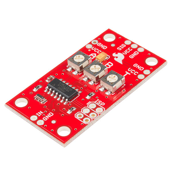
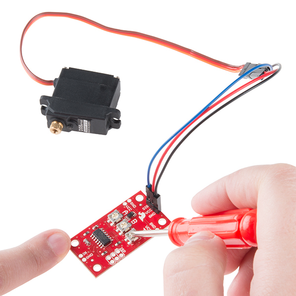
The SparkFun Servo Trigger is a small robotics board that simplifies the control of hobby RC servo motors. When an external switch or logic signal changes state, the Servo Trigger is able to tell an attached servo motor to move from position A to position B. To use the Servo Trigger, you simply connect a hobby servo and a switch, then use the on-board potentiometers to adjust the start/stop positions and the transition time. You can use a hobby servos in your projects without having to do any programming!
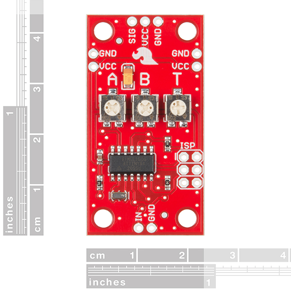
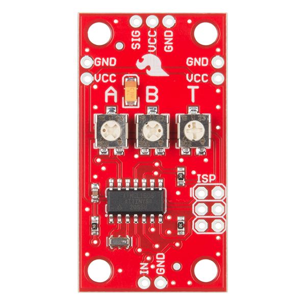
The heart of the Servo Trigger is an Atmel ATTiny84 microcontroller, running a small program that implements the servo control features we are discussing here. On-board each Servo Trigger you will find three potentiometers, "A" sets the position the servo sits in while the switch is open, "B" sets the position the servo moves to when the switch is closed, and "T" sets the time it takes to get from A to B and back. Compared to a servo motor, the Servo Trigger board draws very little current, roughly 5 mA at 5V. Be sure to note that if you’re using the Servo Trigger to control your motor, the absolute maximum supply voltage that should be applied is 5.5 VDC. Additionally, the SparkFun Servo Trigger is designed to make it easy to daisy chain boards – you can simply connect the VCC and GND pads on adjacent boards to each other.
Note: Check out the Hookup Guide in the Documents section below for more advanced tips, configurations, and modes!
Note: This idea originally came from our friend in the Oakland area, CTP. If you see him, please give him a high-five for us.
- Recommended Voltage: 5VDC
- Max Voltage: 5.5VDC
- Current Draw: 5 mA
- Three Control Settings
- A - sets the position the servo sits in while the switch is open
- B - sets the position the servo moves to when the switch is closed
- C - sets the time it takes to get from A to B and back
- Easy Control with Potentiometers
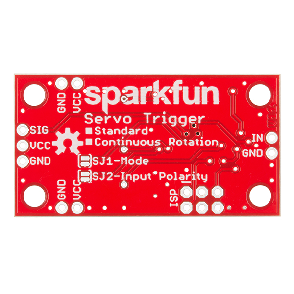
- Configurable Input Polarity
- Configurable Response Mode
- Compatible with Analog Servos
- ISP Header pins Available for Reprogram
- Schematic
- Eagle Files
- Hookup Guide
- Datasheet (ATtiny84)
- GitHub
SparkFun Servo Trigger Product Help and Resources
Servo Trigger Hookup Guide
March 26, 2015
How to use the SparkFun Servo Trigger to control a vast array of Servo Motors, without any programming!
Servo Trigger Programming Guide
May 26, 2016
Looking under the hood of the Servo Trigger -- using the development environment and some finer details of the firmware.
Papa Soundie Audio Player Hookup Guide
April 26, 2018
Add sound effects to your project, prop or costume with Papa Soundie Audio Player.
Basic Servo Control for Beginners
February 25, 2020
An introductory tutorial demonstrating several ways to use and interact with servo motors!
Can I make it go 180 degrees?
Program the Servo Trigger with this hex file to enable 180 degree rotation.
Core Skill: Soldering
This skill defines how difficult the soldering is on a particular product. It might be a couple simple solder joints, or require special reflow tools.
Skill Level: Noob - Some basic soldering is required, but it is limited to a just a few pins, basic through-hole soldering, and couple (if any) polarized components. A basic soldering iron is all you should need.
See all skill levels
Core Skill: Robotics
This skill concerns mechanical and robotics knowledge. You may need to know how mechanical parts interact, how motors work, or how to use motor drivers and controllers.
Skill Level: Rookie - You will be required to know some basics about motors, basic motor drivers and how simple robotic motion can be accomplished.
See all skill levels
Core Skill: DIY
Whether it's for assembling a kit, hacking an enclosure, or creating your own parts; the DIY skill is all about knowing how to use tools and the techniques associated with them.
Skill Level: Noob - Basic assembly is required. You may need to provide your own basic tools like a screwdriver, hammer or scissors. Power tools or custom parts are not required. Instructions will be included and easy to follow. Sewing may be required, but only with included patterns.
See all skill levels
Core Skill: Programming
If a board needs code or communicates somehow, you're going to need to know how to program or interface with it. The programming skill is all about communication and code.
Skill Level: Rookie - You will need a better fundamental understand of what code is, and how it works. You will be using beginner-level software and development tools like Arduino. You will be dealing directly with code, but numerous examples and libraries are available. Sensors or shields will communicate with serial or TTL.
See all skill levels
Core Skill: Electrical Prototyping
If it requires power, you need to know how much, what all the pins do, and how to hook it up. You may need to reference datasheets, schematics, and know the ins and outs of electronics.
Skill Level: Rookie - You may be required to know a bit more about the component, such as orientation, or how to hook it up, in addition to power requirements. You will need to understand polarized components.
See all skill levels
Comments
Looking for answers to technical questions?
We welcome your comments and suggestions below. However, if you are looking for solutions to technical questions please see our Technical Assistance page.
Customer Reviews
4.4 out of 5
Based on 25 ratings:
2 of 2 found this helpful:
Great idea. Wish it went more than 90 degrees.
Everything about this is excellent, except the limited range. I had some projects in mind that would utilize the full 180 range of a servo, so the fact that this limits this by HALF is a bit of a disappointment.
1 of 1 found this helpful:
Works exactly as described
I'm using these triggers with servo motors to control model railroad track switches. They work perfectly and allow me to slow down the movement to more closely model the real world. The only thing I don't care for is that since virtually all servo motors are prewired with standard width female pin connectors. So why aren't the pins installed on the trigger card?
1 of 1 found this helpful:
Multiple Servos
These things are super handy. I've been seeing how many servos one of these boards can run at a time. It seems that if you hook up 3 servos the recommended 5v power won't work but at 6 volts it seems to tolerate it with no issue. (yet)
2 of 2 found this helpful:
Range
It would be nice if the range was > 90° in my case the full 180° would have better for my application.
These couldn't be easier to use
If you are looking for a project to work on as someone new to electronics, or something that is fun to work on with kids, these are really great. No programming involved at all. A perfect way to get straight to building the mechanics with immediate results.
Hope the next version goes 180 degrees
I would of liked some of wiring instructions and instructions on how to use it.
I would of liked some of wiring instructions and instructions on how to use it.
Check the documents tab there should be a full hookup guide on how to wire everything up and instructions on use
Works very well
Alternative to "rolling your own" device to turn servos into shutters, etc. I used this as an alternative to Pololu's Micro-Maestro for similar devices, one with only 1 servo and the other with 3 servos.
This little board worked great for my application.
I have built a suspended model railroad in my man cave around the ceiling. I had mounted above a doorway two lionel gate crossings that had noisy buzzing inductive motors in them. I replaced the electronics with servos and these little boards to control them. For the gate movement I needed both a start and stop position with speed control to achieve a very realistic look. The crossing gates now work and move perfectly with no buzzing. I can see these little boards being used in many model railroad applications.
Servo in action
https://youtu.be/ED9XLVyFcYs
Great feature set
A very useful circuit. Be sure to use good servos. I mistakenly attributed failure to this guy when it was the servo's fault. If the (bad) servo was under load at either end of it's motion range, it would lock up.
Very nice product
This is a beautiful product. Have been looking for a good implementation of a model railroad crossing gate. Didn't find any reasonably cheap one that was readily available. I intend to use this for controlling a micro servo that will run the crossing gate. The range is perfect, although I would love to have one with 180 degree movement too. Simple to hook up, great size - just what I needed.
Next project - turnout switches.
Great for any single-stroke servo application
The speed, as well as start and end positions are easily set with a Phillips head. However, if you want to control this programmatically (e.g. with a GPIO voltage command), you’ll need a transistor. I used this to control a gong ring with a Raspberry Pi. Great product!
Very Useful Device
I am using this servo trigger on my electric lawn spreader gate control.
I am using a 1/4 scale RC Servo, and a 50 amp 50 volt adjustable voltage regulator to mate up the components - - it works great.
However, I would like to have connections to a Bourns 10 turn precision potentiometer in order to vary the control gate for various fertilizers/weed control applications.
Tried soldering to the center pot to control the opening/closing of the gate, but, the pad came off the board - - this is a new board, installed and working properly.
If Only
We need a servo trigger just like this one that can do more than 90°. On my model railroad it could do so many things. I use this one to open garage doors etc. but the doors always need a little more.
Great product!
I use these servo triggers to control servos that opens and closes my shop dust vacuum system blast gates. I run the servo at 6 volts and only connect ground and 'sig' from the trigger.at 5 volts. Works great! Keep making these Servo Triggers. I will buy more.
Love it!!
It's such a great testing tool to assess how and where my servos need to go, saves me tons of programming time doing tweaks and uploading / downloading program edits, instead I just do a simple screwdriver adjust and get the servos exactly how I need them, makes programming positions later a snap! Thank you, just wish they weren't backordered so often, I guess everyone else loves them too!
works like a charm
there is heaps of helpful information at the sparkfun site wehn you buy this module staight out the gate, which is enormous help. I am pleased with how it works would buy another if I ever need one .
Wish it supported high voltage servos
Figured I'd give it a shot and sure enough, it lost its mind on a 2S lipo. It dos say max 5.5 VDC and it works great when used as specified.
Exactly what I needed!
I needed to control a servo for a project (automatic cigar dispenser). Having the three adjustments made setup much easier. Two things I don't like are how fast the servo moves when resetting itself if power is disconnected (minor problem for my project) and secondly it has a continuous drain on the power supply. It drained the batteries in less than 3 days. I solved this problem by adding an on-off switch to the battery. Otherwise, works as advertised.
one of about 10 I ordered is not working well
The A and T pot are responding but there is no response from the B pot. What should I do? sending the Servo Trigger back?
Easy pesy
Spark fun makes this easy. Know need to buy a bunch of components and build your own. Just order their low cost components and you’re in business. I needed one more Chanel for my RC Plane to control the chock and my transmitter was maxed out. This triggered let me put a switch on the side of the airplane and save me hundreds of dollars for a bigger transmitter.
Great product
Works as advertised. A very handy board!
This thing works great!
Hooked this up to the output from an IR sensor and it gave me great control of the two positions of the servo depending upon the presence or absence of the IR beam on the sensor. The pots are a great way to control the positions. Kudos!
Awesome board
I used this with a custom CNC pen plotter to control the pen up/ down movements. This board provides a lot of function in a small package, yes I said that. It was a great way to keep my project clean. I do recommend this product. To see my application visit https://www.youtube.com/watch?v=WUFH7A565E0
Is it possible to trigger this from a 110v outlet getting power? I want servos to turn to open when a wifi controller outlet turns on and them to close when it shuts off. The servos will be powered by a separate outlet that will always be on.
Hi there, it sounds like you are looking for technical assistance. Please use the link in the banner above, to get started with posting a topic in our forums. Our technical support team will do their best to assist you.
Short answer yes and no.
Is it possible to operate this device in reverse?
Ie... take a servo signal input and map a specified signal range to trigger an output?
Hi there, it sounds like you are looking for technical assistance. Please use the link in the banner above, to get started with posting a topic in our forums. Our technical support team will do their best to assist you.
That being said, the answer is no. You'd have to write your own firmware and program the board to do that.
I have assembled the servo trigger, programmed it and it's not working. I am now trying to understand the reason - any help would be highly appreciated. What happens - when I connect power, the servo keeps going in one direction. When I enable input, it doesn't change the direction. I haven't soldered any of the SJ jumpers - everything is left by default. I assembled everything based on the picture on the main page. 10uF capacitor is soldered as on the picture. 0.1uF capacitor polarity as well as resistor and resonator polarity is not important (correct me if am wrong). As for Attiny chip - I have soldered it as shown on the picture (is this the correct orientation?) I have used Attiny84A instead of Attiny84. I didn't change anything in the project in Atmel Studio and flashed the chip as Attiny84. Do I need to change anything in the project for Attiny84A. And if so, what exactly? I have used USBASP programmer to flash the chip. I am not sure it supports Attiny84A but it showed that flashing was done successfully - fuses etc. Also what mode should I use If I would like to have the following - when I press the button servo goes from A to B, when I press the button one more time servo returns from B to A. Should I use the default settings? Sorry, it's hard to understand the explanation about modes since I am not a native speaker. Thank you very much in advance.
Please sparkfun team, help me - the servo moves in one direction when I power it on - no reaction to trimpot adjustments. I don't know what to do.
While the comment sections are great for customer support they are not a good way to contact our support team. Please email techsupport@sparkfun.com if you are having problems. The pictures on our site are taken of boards that have come off our production line so all parts should be oriented and assembled exactly like they would on a shipped board. I believe the Attiny84 and Attiny84A are pin compatible so that shouldn't be an issue. Check if the Attiny84A is listed as an option in your programming environment as sometimes you can't upload code unless you have the exact chip name. As for your scenario it sounds like what you want is a locking button and not a momentary one. The board is designed to move from A to B when the button is pressed and from B to A when the button is not pressed. Again, if you have more questions I would recommend emailing our techsupport department.
Send an email 3 days ago, no reply yet. Could you please kindly check Case #255099?
I understood what seems to be the trouble - I tried to read fuses and for some reason I got this message: avrdude.exe: "fuse" memory type not defined for part "ATtiny84"
Meaning that probably fuses are missing or my usbasp programmer can't read them? How do I set up fuses for this project?
Servo Trigger firmware on the Arduino: I've ported the firmware written by Byron Jacquot for this excellent device. It will control 2 servo motors (pin 9 and pin10 using Timer 1) with independent FSMs and software configurable settings. It's a prototype for a larger project, but this was a great place to start.
Full instructions here
This is awesome! Thanks for posting. :-)
Could you post dimensions for this board? Apologies if I've missed them.
The board outline is 1.7" by 0.9".
The mounting holes are 0.125" in from each corner, and 0.13" in diameter, for 4-40 machine screws.
The dimensions are in the Eagle BRD file. Turn on layer 47 ("Measures") to see them.
Could this board be used with an Arduino to trigger its input? How would it be hooked up?
Where were you guys a decade ago when I made this circuit out of 555s? Could have saved me an afternoon of grief.
http://i.imgur.com/krRLvW0.png
Might I suggest you take your circuit and sell it to the physics folks around the world that are using it in their fancy science learning machines -- it's a far more elegant solution than mine. Although sometimes its worthwhile to ground the power/signal leads for experiments as it prevents erroneous signal noise in high sensitivity environments.
Hey guys, issue I am having....is then I first apply power....the servo does not always start in same position.....when I have my servo arm connected...and if it was to move to random position, then it want to break servo....only when I have board powered, and then connect servo, can I get it to work reliably..... Is there another workaround?? Or is something wrong with my board?? Thx again Kerry
It sounds like something isn't right. It should power up without issues.
What servo motor are you using?
Also, what power supply are you using?
If you can provide links or part numbers for those, I can try to recreate the situation here.
Since you encounter problems when you power everything up together, but it works OK if you power up the trigger, then add the servo, it sounds like there might be some startup interaction between the motor and the power supply. If you have an oscilloscope (or even a DC voltmeter), watch the 5V line while you power up, and see what happens - if it dips or spikes, it might be causing the servo or trigger to get confused. I've seen servos draw an amp or more right when they start, then settle to a much more reasonable draw, maybe 20 mA.
There's some more info about this in the hookup guide, in the Power Notes section.
If you can substitute a different servo or power supply (like 3 flashlight batteries), that might help isolate what's going wrong.
This product is super clever. Nice job.
For model railroad applications, this controller is perfect for driving servos connected to turnouts (switches) or semaphore (signal) blades.
Some suggestions: - Replace the pots with header pins, which tie through a ribbon cable, to a button/pot programming pendant. Save position values in Flash. - Add a third servo position and have a separate input for it or have three input bits. The ability to just ground an input for the position you want is very powerful and convenient. A 2 to 3 Mux/Decoder can be added by the user. - Reduce the price.
Is the sketch code available?
Agreed on the header thing. And it needs another pot for the speed of the return stroke, too.
May I ask what goes into deciding which Attiny chip was selected?? Sort of why Attiny84 vs. 85 vs. ?? and the like.
Two factors, mainly:
First, the application determined the minimum number of pins required:
Of course, the pins and peripherals also have to be setup such that the functions aren't mutually exclusive. That caused some problems with the 8-pin Tinies that I looked at.
Second, availability. We already use the 84 in the Tiny USB Programmer stick, so it's a part that's already in our pipeline. We also have the DIP-14 version in stock, which I built my initial prototype around.
So, yeah, pins and availability.
Can I use Attiny84A instead of Attiny84? I guess I can't since Attiny84A has only 1 PWM, doesn't have UART and I2C. Could you please confirm? It's also not very clear which voltage should capacitors have - I have ordered 6.3 DC. Is it correct?
Thank you very much for what you have been doing.
That depends on what you are trying to do. The board comes populated and programmed, but if you are trying to build your own it depends on what feature changes you want and what pins they would need.
I am trying to assemble the same servo trigger board and I don't need any feature changes. The reason I am asking - I would like to build this using the brd files provided. I am now trying to purchase Attiny84 but it's twice as expensive as Attiny84A. So I would like to know, whether I can use Attiny84A. It's not clear whether second PWM, UART and I2C are used in this project. Or are you trying to tell that building this is not possible? Thank you very much in advance.
According to Atmetl the ATtiny84A is a functionally identical drop-in replacement so it should work fine. As for the capacitors, the voltage rating is really how much voltage they can handle, we use a 16V and a 25V on this board, but we use those parts on a lot of boards so we've selected values that will work with most of our boards.
I am asking, because I have noticed that Attiny84A has only one PWM timer, instead of 2 in Attiny84. It also doesn't have UART and I2C. So it would be good to know, if Second PWM timer, UART and I2C are used in this project.
Where are you seeing that. I'm looking at the 2 datasheets and the pinouts with all pin descriptions is identical for both the ATtiny84 and the ATtiny84A. Neither has UART, both have I2C and the datasheet says "two PWM Channels" for both chips.
Thak you very much indeed. Looks like the description in the shop is not correct:
https://www.arrow.com/en/products/attiny84-20ssu/microchip-technology https://www.arrow.com/en/products/attiny84a-ssf/microchip-technology
This uses analog potentiometers to control analog parameters (timing), but it does it with a digital microcontroller. I remember the days when this would have been implemented with a couple of timers and perhaps a shunt transistor or analog switch. In fact, I'm tempted to grab a 556 and 4066 and give it a try.