- Home
- Product Categories
- Temperature
- SparkFun Thermocouple Breakout - MAX31855K

SparkFun Thermocouple Breakout - MAX31855K
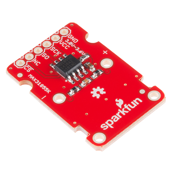
The SparkFun MAX31855K Thermocouple Breakout is a simple 14-bit resolution, SPI-compatible, serial interface thermocouple digitizer that makes reading a wide range of temperatures possible. A thermocouple works by taking two wires made of dissimilar metals, connecting them at the two ends, and making a temperature gradient between one end and the other (a 'hot' end and a 'cold' one). Once this is achieved, a voltage potential is formed and current flows. The SparkFun Thermocouple Breakout takes a standard Type-K thermocouple in one end, digitizes the temperature measured and sends that data out the other end via a SPI interface, thereby interpreting the data and translating it for you to read!
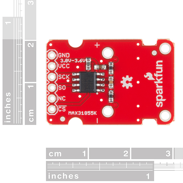
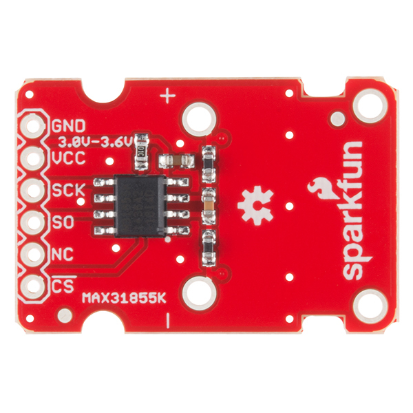
With the SparkFun Thermocouple Breakout, the thermocouple’s hot junction can be read from -200°C to +700°C with an accuracy of ±2°C while the cold junction, inside the MAX31855K, can only range from -20°C to +85°C while maintaining ±2°C accuracy. The MAX31855K constantly measures the temperature of the cold junction using an internal temperature-sensing diode. The MAX31855K requires a power source from +3.0V to +3.6V (+3.0V nominal) and only draws 1.5mA maximum.
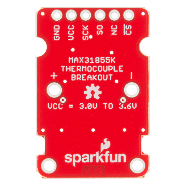
The Thermocouple Breakout is designed to accept a standard thermocouple connector, for convenience and compatibility with probes you may already own. These connectors aren’t necessary, and you could solder a thermocouple directly into the through-holes labeled ‘+’ and ‘-’. If you decide to solder the thermocouple directly to the breakout board, it is recommended that the thermocouple be mounted for strain relief to avoid breaking the thin wires. Notches for a zip-tie or wire wrapping have been provided in the PCB opposite the header for this purpose.
- 14-bit Resolution
- SPI-Compatible, Serial Interface
- -200°C to +700°C Temperature Reading with ±2°C Accuracy
- 3.0V to 3.6V (+3.0V nominal) Required
- Accepts Type-K Thermocouple
- Schematic
- Eagle Files
- Hookup Guide
- Datasheet (MAX31855K)
- GitHub (Design Files)
- GitHub (Library & Example Code)
SparkFun Thermocouple Breakout - MAX31855K Product Help and Resources
MAX31855K Thermocouple Breakout Hookup Guide
November 5, 2015
Learn how to take readings with a k-type thermocouple using the MAX31855K cold-junction-compensated k-type thermocouple-to-digital converter.
Core Skill: Soldering
This skill defines how difficult the soldering is on a particular product. It might be a couple simple solder joints, or require special reflow tools.
Skill Level: Noob - Some basic soldering is required, but it is limited to a just a few pins, basic through-hole soldering, and couple (if any) polarized components. A basic soldering iron is all you should need.
See all skill levels
Core Skill: Programming
If a board needs code or communicates somehow, you're going to need to know how to program or interface with it. The programming skill is all about communication and code.
Skill Level: Rookie - You will need a better fundamental understand of what code is, and how it works. You will be using beginner-level software and development tools like Arduino. You will be dealing directly with code, but numerous examples and libraries are available. Sensors or shields will communicate with serial or TTL.
See all skill levels
Core Skill: Electrical Prototyping
If it requires power, you need to know how much, what all the pins do, and how to hook it up. You may need to reference datasheets, schematics, and know the ins and outs of electronics.
Skill Level: Rookie - You may be required to know a bit more about the component, such as orientation, or how to hook it up, in addition to power requirements. You will need to understand polarized components.
See all skill levels
Comments
Looking for answers to technical questions?
We welcome your comments and suggestions below. However, if you are looking for solutions to technical questions please see our Technical Assistance page.
Customer Reviews
4 out of 5
Based on 8 ratings:
1 of 1 found this helpful:
breakout works as expected!
Using two of these to pull box/internalMeat temperature for an electric smoker on RaspberryPi. Works great!
1 of 1 found this helpful:
Works great
Just connected it to an ESP8266 Thing Dev board. Using it to monitor the temperature of a pottery kiln. It will operate above the temperature range listed in the description. It was reading within 5-10F of the kiln controller at 1950 degrees F (the two thermocouples were in slightly different locations).
5 of 5 found this helpful:
Good response up till my device caught fire
It gave good and accurate readings (was comparing it to a commercial unit) and was very responsive. Log files also show that it reacted quicker than the commercial unit, and when it spiked to 770 as my device burst into flame, I was able to record the demise of my electronics very accurately. Only complaint is that while the device itself said +700 C, most of the components around it melt way before that. I recommend the thermocouple, and advise against lighting your electronics on fire.
Exactly what I needed
Talked SPI to my ESP8266 right off the bat and now I can read the temperature of my pizza oven from inside the house.
0 of 1 found this helpful:
Needs work...
I'm a tremendous fan of SparkFun but this breakout needs work. The direct connections for the thermocouple aren't predrilled which risks damaging the board, there is no built in voltage leveling limiting the microcontrollers you can use unless you want to add a voltage leveler to your project. The "-" and "+" on the board should also be labeled "red" and "yellow"--going on the web there is a lot of misinformation about how the color coding works for thermocouples. Documentation is poor added to the breakout labeled cs, nc, so, sck when it would be a lot simpler to go with clk, cs, do. If you are going to use it with a pro-mini you'll get it to work but my guess most people want it for more sophisticated applications.
Works as but needs electrical isolation for many applications
Hookup was easy and the board works as advertised.
However, using for example the SEN-13715 stainless steel thermocouple I got "probe is shorted to GND" readings constantly. Turned out that the thermocouple itself is electrically connected to the stainless housing. I had naively mounted the thermocouple in the wall of a metal (grounded) enclosure and then connected the USB from my Arduino to my (grounded) laptop. Doesn't work!
So now I need to either float the entire arduino control circuit in an insulated box or add an opto-isolator and floating DC supply between the arduino and the breakout board.
Still, the board does provide an easy way to get started, and in many applications one can keep the thermocouple electrically floating.
Doesn't work with MKR1000 unless ...
You'll need to comment out the call to SPI.begin() in the cpp file that is part of SparkFun's library for this breakout and call SPI.begin() in your setup() function, or it won't work on MKR1000.
great ...
I used libmpsse to write some software to get the temperature data. I want to connect it to artisan ( https://artisan-scope.org ) to roast coffee. I'll probably port the libmpsse to an ARM MCU, such as the "blue pill" or Nordic 52840 (using Zephyr project OS).
Thank you for making your breakout board for this chip compatible with attaching an industry standard miniature (flat pin) thermocouple connector. Other vendor(s) who have made a breakout for this chip seem to think a screw terminal is appropriate...
What is the purpose of the capacitor and two inductors on T- and T+?
Not sure, the engineer on this product has since moved on and there isn't any information documented on that. My best guess is that it might be a passive filter of some sort?
Are the two inductors (L1 and L2) supposed to be 470mH or are they actually resistors?
Hi, I have a question, I have 2 breakout boards with their respective thermocouple, I am trying to measure the tempearute in a metallic table in 2 different places. Everything works just fine when the probes are not in contact with the table, but as soon as both touch any metallic surface I got an error in both measurements. I am using an Arduino Mega for the test, I am using the 3.3V from the Arduino for supplying the breakout board. Do you know what the problem may be?
Regards
Everything I have is 5V rather than 3.3V so I needed to level shift to get this working with Arduino. The SF logic level converter (BOB-12009) works well for this but the TXB0104 (BOB-11771) does not. The TXB0104 seems to attenuate the Arduino signals down too low or?. The reason is probably obvious to the engineers but it is not to me. Just FYI.
Interesting. I've definitely use the TXB0104 for fast(ish) SPI in the past with success. Do you have the higher voltage on the correct port (VCCA ≤ VCCB)? Do you have OE pulled to VCCA? The BOB-11771 makes it easy to get this right, so I assume you do. I'd need to see the setup to debug it.
Regarding the thermocouple connector.... please move it up in the 'recommended products' list.
"-200°C to +700°C Temperature Reading with ±2°C Accuracy" might be a little misleading. The chip is ±2°C accurate to it's internal linear model of the thermocouple temperature as a function of thermocouple voltage. The voltage produced by a thermocouple is not a linear function of the temperature (though a linear model is okay for many uses).
For example, at 700º, a K-type thermocouple generates 29.129 mV. [1] This chip calculates the temperature using T = V / (41.276 * 10 ^ -6). So for 700º, it'd report 705.713 º ± 2 º.
At -200 º the problem is much worse. -200 º on a K type thermocouple is -5.891 mV. This chip would report -142.72 º ± 2 º.
Also, the uncertainty of the cold junction measurement needs to be added to the uncertainty of the thermocouple measurement if you're talking about the accuracy of a typical temperature measurement using this chip. Even ignoring the problems due to the linear model, the uncertainty of a temperature measurement should be considered to be ±4 º.
You could take the value reported by this chip and in your code reverse the linearisation and CJC compensation to get the thermocouple voltage. You could store the thermocouple voltage table in your micro (or some clever piecewise linearisation of it) and use that to get a more accurate temperature measurement, but it seems like a lot of work compared to using your own ADC and CJC sensor.
[1] http://www.ni.com/white-paper/4231/en/#toc2
Correct. I'm not sure how Maxim justifies that claim. Note 4 'deep' in the datasheet reads "Not including cold-junction temperature error or thermocouple nonlinearity". This device is comparable to many in its class. If you look at the NIST tables you can see that for the best readings you must select the temperature range of interest. Since the method of forming the cold-junction connection, the choice of thermocouple, and the desired range is up to the end user it's difficult to preconfigure the device with extreme accuracy. Ideally one would calibrate the system by building a table checked against a reference. The freezing points of metals are apparently used for some calibrations. Thanks for documenting some of the issues for the less informed to be aware of.