- Home
- Product Categories
- LED Drivers
- SparkFun Large Digit Driver

SparkFun Large Digit Driver
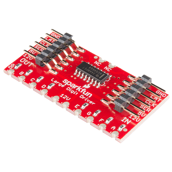
The SparkFun Large Digit Driver is a chainable controller backpack that can be soldered directly to the back of our large 6.5" 7-segment displays. Large numerical displays are a great addition to any project where you want to be able to see information at a distance. Scorekeepers and lap timers would be a great application for large 7-segment LED displays.
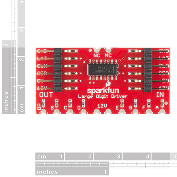
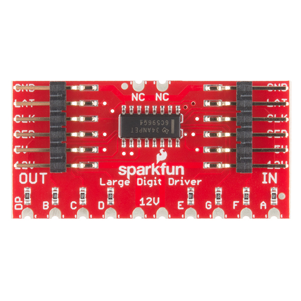
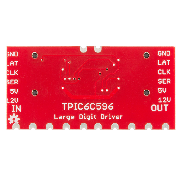
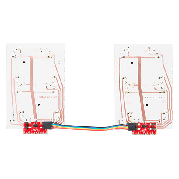
The SparkFun Large Digit Driver can easily be attached to the back of the 7-segment display by soldering all 10 castellations pins at the bottom of the board as well as the two additional castellations at the top. Keep in mind that the Large Digit Driver requires both 12V for the LEDs and 5V for the on-board TPIC6C596 IC. Each driver is equipped with six input pins and six output pins, these make the driver capable of being chained together. The input/output pins are listed as GND (Ground), LAT (Latch), CLK (Clock), SER (Serial), 5V (Power for the driver IC), and 12V (Power for the 7-segment display).
The Large Digit Driver has 8 inline 15 Ohm resistors to limit the current through each segment on the 6" display to 20mA (as dictated by the display datasheet). You will need approximately 160mA of current at 12V for each digit in your display.
We used the SparkFun Large Digit Driver in our AVC Battle-Bot Arena to display times and scores!
- Designed to attach directly to the 6.5" 7-Segment Display
- IC Operating Voltage: 5V
- Sinks up to 250mA per channel
- Chainable to another Large Digit Driver
- Castellated Mounting Holes
- Schematic
- Eagle Files
- Hookup Guide
- How to Solder Castellated Mounting Holes
- Datasheet (TPIC6C596)
- SparkFun Speed Trap Wishlist
- GitHub (Design Files & Example Code)
SparkFun Large Digit Driver Product Help and Resources
Large Digit Driver Hookup Guide
June 25, 2015
Getting started guide for the Large Digit display driver board. This tutorial explains how to solder the module (backpack) onto the back of the large 7-segment LED display and run example code from an Arduino.
Mind your voltage!
Take extra care to note the placement of the 5V and 12V pins. They are right next to each other, and we have seen instances where 12V was accidentally applied to the 5V line. This will not end well. It will usually wind up frying the microcontroller, resulting in a nonfunctioning board, and possibly tears.
Core Skill: Soldering
This skill defines how difficult the soldering is on a particular product. It might be a couple simple solder joints, or require special reflow tools.
Skill Level: Competent - You will encounter surface mount components and basic SMD soldering techniques are required.
See all skill levels
Core Skill: Programming
If a board needs code or communicates somehow, you're going to need to know how to program or interface with it. The programming skill is all about communication and code.
Skill Level: Rookie - You will need a better fundamental understand of what code is, and how it works. You will be using beginner-level software and development tools like Arduino. You will be dealing directly with code, but numerous examples and libraries are available. Sensors or shields will communicate with serial or TTL.
See all skill levels
Core Skill: Electrical Prototyping
If it requires power, you need to know how much, what all the pins do, and how to hook it up. You may need to reference datasheets, schematics, and know the ins and outs of electronics.
Skill Level: Rookie - You may be required to know a bit more about the component, such as orientation, or how to hook it up, in addition to power requirements. You will need to understand polarized components.
See all skill levels
Comments
Looking for answers to technical questions?
We welcome your comments and suggestions below. However, if you are looking for solutions to technical questions please see our Technical Assistance page.
Customer Reviews
4.5 out of 5
Based on 8 ratings:
2 of 2 found this helpful:
Needs revision
Would be a real winner with no resistors and STANDARD SPACING ON THE DIGIT OUTPUTS for pins! Especially since there are no more SF large digits?
Works great
I used six of these with the giant 7-segment displays to make a giant clock for a large meeting hall. They do exactly what they are supposed to do.
Good instructions, solid board
I'm building a "cash booth" for my company, where we put the "employee of the month" in a booth with a couple hundred bucks and watch them flail around for a bit. We use these large digits (and the driver boards) for the timer mechanism, and they're a huge part of making the booth look "legit". Programming them using the given examples was probably the easiest task outside of making the buttons work. If you have a project where you need people to see a big number from 100+ feet away across a crowded room, this it the way to go!
Awesome!
I am using two of these to drive two 4" high seven segment LED displays (common anode). I am supplying this board with 9V at the 12V input and have two boards daisy-chained together for two segments. Gives full power to each segment rather than multiplexing the segments. Segment brightness does not vary at all depending on the number of segments lit (which is a good thing). Very simple to connect and program with an Arduino. If not for this, I would be using 14 PNP transistors and resistors. Very pleased with this product.
These things are great!
The only thing I wish was that there was a version that had more area at the bottom to solder. I struggled to get the tiny solder dot on, but in the end it made a good connection and works great.
Won't work on power-up
This seems to be a workable driver chip for the large 7-segment displays. However, the enable pin is hard-wired, so most of the time when powering on the unit, all of the segments are lit. Also, when powering on, they appear to "lock up" the arduino until the reset button is pressed. I have tried adding delays of several seconds on on startup, and isolating the 5V supply (not using the arduino 5V out), but they still require a reset. Lastly, because this is just a basic shift register and doesn't do PWM, the brightness of the segments varies depending on how many are lit at one time.
Hello!
Sorry to hear about the issues with getting the 7-segments working. Have you contacted our technical support department @ techsupport@sparkfun.com - they're usually great at getting devices working.
terrific driver
Used six of these to power some 3.4" seven segment displays that I got off Amazon. I just ran 9v through the unit instead of the 12v printed on the pcb.
Hi, I have a Sure DP22811 (2 digit, 2.3" high, 7 segment display), do I need two large digit drivers to power my display? Also, similar question, would I need 2 shift registers to run the display? Thanks!
Could 9 of these be chained together connected to some rather large LED seven segment displays? The displays would be 12v made with LED strip lights.
9 displays all connected.
In principle, yes. The TPIC6C596 is limited to 250mA per segment so don't go above that and you should be fine.
That shouldn't be a problem should it with the external 12v inputs? The 12v doesn't run through the shift register does it?
Please see the TPIC6C596 datasheet. It is a shift register wired to sink the 12V source across the LED segments.
It is important to include the CLR line, especially for a clean start. It is also desirable that the power supply lines (12V, 5V, GND) are thicker since when placing more than 9 displays the current already exceeds 1A.
In general it is good product.
I'm having a noise issue. I have 4 of these strung together with the large 7-seg displays and the segments will flash randomly during normal operation.
I was at the Sparkfun factory last Friday and noticed that Nate's safe-cracking robot's sign had capacitors on each digit. I didn't make a note to the size of each cap or where exactly they were placed but I'm thinking my noise problem will be solved with these caps.
Could someone give me some guidance on adding caps to my large digit driver to minimize noise?
Thanks, Jonathan
Hi Jonathan - Thanks for taking the tour!
The display on the safe cracking robot is a bad example. When the motor changes direction quickly it (sucking up a few amps) pulls down the 12V power supply significantly, which causes the display to flash. The display doesn't lose its memory, it just looks bad. I added caps in an effort to reduce blinking of the display but the caps didn't end up helping (I didn't have ones big enough). I was using 25V/1000uF caps placed across the 12V/GND pins.
These displays can pull a fair amount of current. You might try adding more decoupling to your power supply but random flashing is weird, it will usually be associated with something going on in your system (such as motors turning or some piece pulling in a low of current). If you're experiencing flashing either isolate your 12V supply or be sure your 12V supply has enough current to keep the 12V rail above 12V.
I gave up trying to control the LEDs directly with the Raspberry PI and added an Arduino Pro Mini in between. Everything works as expected now.
I'm looking at the datasheet and wondering if the source voltage and logic voltage should be the same; 3.3v?
Random flashing might not be the correct way to describe it; its more like the segments randomly change as if they are getting a signal to display something else.
There is a motor but its completely separate running on 120 volts. There is however a beefcake relay turning the motor on and off. When the relay is switched the display changes.
I'm controlling everything with a Raspberry Pi. Is it possible that the 3.3v GPIOs are the issue?
i cant work with nodemcu board (esp8266), any idea?
May I know if I want to make the exact same things with Lidar-lite v3, how much would be the maximum speed which it can detect, what about with Lidar-lite v2.
What a fun question to try to answer!
The LIDAR-Lite v3 can achieve 500Hz with a max read range of 40m. If you were to cover roughly 38m in 1/500 of a second that would be 19,000m per second or 42,500 miles per hour.
If you are building a copy of the speed trap there are other bottle necks to consider. Namely, the maximum read rate while running the Arduino sketch. The sketch is here and waits 50ms between reads. This is 20Hz. And for this discussion let's say the LIDAR (v2) can read to about 15m reliably so using the same math we get 300m per second or 671 mph.
I'm curious, what are you building?
Thank you very much for prompt reply, in fact my house is located in corner block where drivers turning from main road to our allay, I thought it might be a good idea if I show them their speed but not sure if legally I can do or not. anyway thank for consideration.
Just starting my first project with these and got 2 large 7-segment displays and the large digit drivers working with my Arduino Uno. Awesome tutorials SparkFun...thank you. So I'm making a small scoreboard for my sons room which I plan on also working as a clock while not in "scoreboard" mode. The numbers can be very bright when dark and I'd like to add a dimmer to this project. I've been playing with a potentiometer and PWM for with some simple LED dimming and got that working easily. How can I get the large 7-segment displays to dim with the large digit driver. Is this even possible? Thanks in advance for any guidance.
Awesome project idea!
Hmm, dimming might be tricky. You could used a variable power supply and lower the 12V to say 10V. This should dim the LEDs quite a bit but I'm not sure how finicky the dim-ability will be.
Maybe you could update the TPIC IC really to get PWM control of the segments. You'd need to move the postNumber routine to an interrupt that ran regularly and probably faster than 60Hz (so that your eye doesn't notice it).
Too bad the ~G pin of the TPIC6C596 is shorted to GND. Had it been exposed a PWM on that pin would have provided a means to dim.
For anyone trying to create a simple arduino based countdown timer. Here's the necessary function modified from the rest of the program provided in the tutorial.
These boards worked out great. So I updated my pace/walk clock design and code to use them and posted an intractable to help anyone do the same. http://www.instructables.com/id/100-Pace-Clock-or-Wall-Clock/
Help please! Trying to copy the GPS wall clock to the big LED 7-segs. I am having a tough time getting the basic display code to run out to 6 digits. I get to 5 but adding one more gets wrong results. Have 7 hours into this - (no big deal) but I'm missing something that I don't think I'm going to solve. Thanks in advance for any pointers
I removed the DP and other logic to simplify down the code and am only posting the relevant lines - have the setup{} and byte declare just as in both of the example programs here:
Ok, spent longer than it should have taken me, but finally figured out that the demo code had some ints in there, and once you get over 32,767 it'll start to freak out. I've switched it to use longs and everything started working. Here's the code that ended up doing the trick for me:
While I would hate to deny you the fun I had figuring this out - here you go:
https://github.com/bethanysciences/BIGLEDClock
complete write-up and working code...
Heck ya! Nice project! Thanks for writing that up.
I'm running into a similar problem, I picked up six of these and have been testing adding them one at a time. I can get up to four with no problem (just cycling through all 1's, all 2's, etc), but once I add a 5th, the numbers will freak out once they get to the 3's (and the same thing happens if I add the sixth digit).
They do all reset back to 0's once the loop hits the modulus limit, and I've tried adding delays before writing the latches, but nothing seems to be working. Anyone have any ideas?
Where can I get the link to the circuit for the Speed Trap? Will appreciate if you kindly post the link somewhere.
https://github.com/sparkfun/Speed_Trap
I would like to build a speed trap, Do you have a tutorial on how to build it with code etc. This is a great project
https://github.com/sparkfun/Speed_Trap
WARNING: before soldering, I'd strongly recommend putting a piece of tape on the back of this board to insulate the vias from the exposed copper traces on the 7 segment display.
On my board, the via connected to pin 10 (RCK) on the shift register wasn't fully covered by the solder mask and ended up bridging with the exposed 12V trace on the back of the 7 segment board. This caused a short from 12v to pin 10 (RCK) on the shift register, which made ~12V available on all the input pins as well as the 5V pin. I fried a couple Arduinos before I figured out what was happening. Seems like the shift register is fried too. Now that I've pulled it off the 7 segment board it's no longer trying to supply 12V on all the input pins, but it doesn't seem to do anything anymore.
I'm going to order some new shift registers and try to salvage the board :(
Hi John - Really sorry to hear your board got fried :/ I wanted to point folks at the hookup guide - we do recommend a bit of electrical tape to isolate the backpack for this specific reason. Sorry you had a bad experience but I'm glad you found the culprit!
Really wish there was an RC network on the CLR\ pin to ensure the display is blank on power up. Otherwise, it works well.
This looks familiar...
http://i.imgur.com/8pIqBmb.png
thanks Kirby
As well as the code, if you offer a parts list not unlike other demos I believe you would sell sell sell
Github link seems to be broken
It should be working now! :)
Lol, nice video, that's one way to get your employees blood flowing ;)