- Home
- Product Categories
- Addressable
- Flexible LED Matrix - WS2812B (8x32 Pixel)


Flexible LED Matrix - WS2812B (8x32 Pixel)
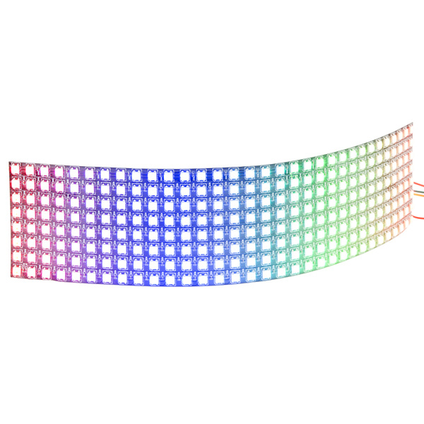
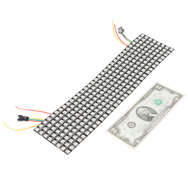
This large 8x32 pixel WS2812B (or "NeoPixel") flexible LED matrix is a great way to add an impressive amount of color while still being able to individually control each LED. We aren't kidding around, that's 256 individually addressable LEDs on a 320mm x 90mm flexible panel. You can create animations, games, or even incorporate them into a fun e-textiles project. On top of all that, thanks to its flexible backing, this LED Matrix can be bent and bowed to fit onto almost any curvy surface.
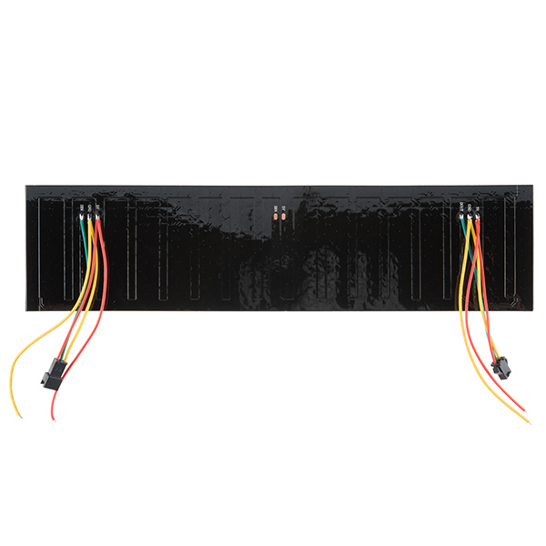
These panels require a 5V low voltage input for power which needs to be able to source a good amount of current – up to 5A in most uses (15A if all LEDs are set to bright white, which is NOT recommended). Attached to each flexible LED matrix are two 3-pin JST SM connectors and two sets of bare power cables (input / output), which provide you connections for DC5V+, COM-, DAT, and GND. Needless to say, if you are looking for a large panel of addressable LEDs to fit the contours of almost any surface you've come to the right place.
Note: Repeated / Over bending may significantly reduce the structural integrity of the flexible panel. It is advisable when bending it over curved surfaces to not be too rough with this product as you may damage LED traces or the panel itself. Needless to say, do NOT fold this matrix in half!
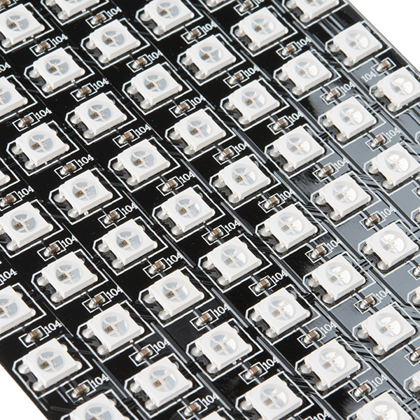
- 256 WS2812B LEDs
- 5V Supply Voltage
- Beam Angle: 140 deg.
- Watt Consumption: 51W Max (per 60 LEDs)
Flexible LED Matrix - WS2812B (8x32 Pixel) Product Help and Resources
LED Cloud-Connected Cloud
February 22, 2016
Make an RGB colored cloud light! You can also control it from your phone, or hook up to the weather!
Mean Well LED Switching Power Supply Hookup Guide
June 28, 2018
In this tutorial, we will be connecting a Mean Well LED switching power supply to an addressable LED strip controlled by an Arduino.
WS2812 Breakout Hookup Guide
July 24, 2013
How to create a pixel string with the WS2812 and WS2812B addressable LEDs!
Core Skill: Electrical Prototyping
If it requires power, you need to know how much, what all the pins do, and how to hook it up. You may need to reference datasheets, schematics, and know the ins and outs of electronics.
Skill Level: Competent - You will be required to reference a datasheet or schematic to know how to use a component. Your knowledge of a datasheet will only require basic features like power requirements, pinouts, or communications type. Also, you may need a power supply that?s greater than 12V or more than 1A worth of current.
See all skill levels
Comments
Looking for answers to technical questions?
We welcome your comments and suggestions below. However, if you are looking for solutions to technical questions please see our Technical Assistance page.
Customer Reviews
4.5 out of 5
Based on 6 ratings:
4 of 4 found this helpful:
Very cool display!
I'm a HS computer science teacher with some background in electronics (I built synthesizers when I was in HS 30 years ago) and microcontrollers (2.5 yrs playing with Arduino), and I was able to get this hooked up fairly easily. There are some things I'll pass on to other people that might be new to all this that would have made it even easier.
I hooked it up using F-M jumper wires on the 3 pins of the male JST connector. 5V and GND went to VCC and GND on a PRT-13032 breadboard power supply stick. I powered the stick with an AC Wall Adapter and with a 9V battery. Did a lot of display testing during a 3-hr period on the 9V battery and didn't notice any loss of brightness (more below). From the Arduino, I jumpered GND to the same GND bus the power supply and display were connected to (without this, the display sort of worked, but gots lots of random pixels lighting up), and connected Pin 6 to DIN on the display (the Matrix Library says you can use any pin).
I also hooked up 2 displays by connecting the female JST on one display to the male JST on the 2nd display. Worked fine.
To drive the display, the product page says you need the Matrix Library https://github.com/adafruit/Adafruit_NeoMatrix but for the Matrix Library to work, you also need the NeoPixel library https://github.com/adafruit/Adafruit_NeoPixel and the GFX Library https://github.com/adafruit/Adafruit-GFX-Library
The Matrix Library comes with a "matrixtest" sketch. Setting up this panel required the following code:
// for SparkFun Flexible LED Matrix - WS2812B (8 tall x 32 wide Pixel) - SF P# COM-13304
// using only 1 panel
//Adafruit_NeoMatrix matrix = Adafruit_NeoMatrix(32, 8, PIN,
//  NEO_MATRIX_BOTTOM  + NEO_MATRIX_RIGHT +
//  NEO_MATRIX_COLUMNS + NEO_MATRIX_ZIGZAG,
//  NEO_GRB            + NEO_KHZ800);

// using 2 panels in sequence, using tiled matrix constructor specifying side by side tiles (64 wide x 8 tall)
//Adafruit_NeoMatrix matrix = Adafruit_NeoMatrix(
//    32, 8,                                       // matrix width, matrix height
//    2, 1,                                        // number of tiles wide, number of tiles high
//    PIN,                                         // data pin
//    NEO_MATRIX_BOTTOM  + NEO_MATRIX_RIGHT +      // matrix layout
//    NEO_MATRIX_COLUMNS + NEO_MATRIX_ZIGZAG +
//    NEO_TILE_BOTTOM    + NEO_TILE_RIGHT +
//    NEO_TILE_COLUMNS   + NEO_TILE_PROGRESSIVE,
//    NEO_GRB            + NEO_KHZ800);            // LED type from Neo_Pixel

// using 2 panels in sequence, using tiled matrix constructor specifying over/under tiles (32 wide x 16 tall)
Adafruit_NeoMatrix matrix = Adafruit_NeoMatrix(
    32, 8,                                       // matrix width, matrix height
    1, 2,                                        // number of tiles wide, number of tiles high
    PIN,                                         // data pin
    NEO_MATRIX_BOTTOM  + NEO_MATRIX_RIGHT +      // matrix layout
    NEO_MATRIX_COLUMNS + NEO_MATRIX_ZIGZAG +
    NEO_TILE_BOTTOM    + NEO_TILE_RIGHT +
    NEO_TILE_COLUMNS   + NEO_TILE_PROGRESSIVE,
    NEO_GRB            + NEO_KHZ800);            // LED type from Neo_Pixel
The Matrix Library has a brightness function. Set at 10, the display was readable in average indoor light. Set at 100, it was very bright.
2 of 2 found this helpful:
OMG! It's full of stars!
I like this panel a lot... Have not done much with it yet other than make pretty colors, but I'm looking forward to ordering a second one and making an obnoxious messenger bag.
All of the cautions about running the panel had me a bit worried about running it flat out and melting it... So I didn't ;-) But I can tell you that it has been running FastLED (check it out!) random noise demos for close to a month now 24/7 and is barely warm, and seems solidly made.
I've see it go 9-13°F over ambient with heavy bright animation so very usable... Say, scrolling full height text at full brightness, or doing a Larson chaser thing at full bright white, 8 lights wide... Maybe once I get a second one I'll feel a bit better about cranking it up and playing chicken :-)
3 of 3 found this helpful:
Nice Matrix
Solid, works well, something to note, as I don't see it mentioned in the available documentation, and I chose not to use the provided libraries (if it is in there): The LEDs are sequential, but in a back and forth manner- for example, if the LED matrix is represented by a 8x32 matrix, with 0,0 in one corner and 7,31 in the opposite corner- the sequence goes from 0,0 to 0,7 then 1,7 to 1,0 then 2,0 to 2,7.
Lots of fun
The flexible LED panel works great and we have been generating some very interesting effects. With a few lines of code you can generate random colours to random addresses and the effect is hypnotising. It is important to watch the power consumption though - these things draw a heap when you stoke them up. On the other hand they are very bright!
Nice panel
Just like hazmat said, the pattern is zigzag. The product is solid. Here is some FastLED code to help you visualize the sequence from 0 to 255.
http://pastebin.com/RAbGTpgg
Lots of fun--works great--very bright.
I used the LEDText library (based on the FastLED library) and everything went well and was easy to set up. Video can be seen at www.pelowitz.com/DSCN2760.mp4
Am I the only one who read "(15A if all LEDs are set to bright white, which is NOT recommended)" and immediately wanted to try it?
It's an interesting effect if you don't have a strong enough supply - the lights toward the end gradually turn to orange/red one by one. I assume this is because blue and green suck more current.
Is it possible to cut the sheet w/out damaging it?
i cut mine into two 8x16 panels. seems to work great
Oh boy if this was a mesh or had holes in the plastic, it would be perfect for a daft punk helmet!
Yes, is there room to bore holes between the traces on the 'board' and if not can y'all look at a design that either allows or has holes in between the LEDs? This would also simplify attaching these to fabric as you could use the holes to sew them in.
Specifically I was looking at this problem for a daft punk helmet a while back and one of the things I considered for a denser panel was rotating the actual pixels by 45 degrees, that would simplify running power to them as well as the data pins would practically be touching... just a thought. Hope to see these back in stock soon, will definitely order either way.
I immediately thought Daft Punk helmet when I saw this! I can't imagine how you would see out of it though...
What PSU would you recommend for this?
I use this: for all my LED array projects....
http://ironsheep-ios-fun.blogspot.com/2014/04/custom-hardware-test-platform-for.html
uP is 8-core 32-bit processor for ~$7, control panel for display content is my iPhone/iPad with coms over Bluetooth LE. Of course, i'm not sending the data over the Bluetooth LE at display rates... just controlling what is displayed and providing full interaction (e.g., drawing/coloring pixel by pixel) when not letting device manage what I've told it to display....
Basically I can drive the array shown at > 120 frames / second. so seems to be enough horse power... ;-)
-Stephen, KZ0Q
Tindy plox...
If you're wanting something portable, I've been able to drive a strip of 144 WS2812 LEDs (and an Arduino to control them!) directly off of a nominal 3.7v LiPo battery -- no voltage boost required. YMMV.
15A is 80% of 18.75A so this guy would do nicely.
Haven't seen a $2 bill in ages!
I actually have one in my desk drawer
I've been working on a display using this and a Microchip PIC32- video of it in operation is here: https://youtu.be/XUCN45TIdpM - the text is generated from an ASCII string and being written to the display via DMA, so it should not be very processor intensive. I've got it in a Github repo https://github.com/MattAtHazmat/PIC32LEDStrip, but it is way out of date right now, as I'm not quite an expert at Git... I messed something up, and I've been spending my time working on the code rather than figuring out Git.
a couple things:
POWER: people are super concerned with the power draw of this thing. it isn't that bad, if plan for your final application. i'm displaying text, in colors, over about half the panel, so maybe 5% of the leds are even used at any given time. from there my colors and brightness knock it down another 5%. now, im looking at less than an amp at maximum and about to run the entire thing off this battery and parts for at least a couple hours. https://www.sparkfun.com/wish_lists/113501
yes. it worked with a 3.7v battery (no boosting to 5v) and 3.3v data line from my teensy. good times!
BENDING : How much can i bend it? meaning what is the minimum bend radius you'd suggest? do you test these for bend and rebend cycles? what if there is just bent once? how bendie is it? I made this by bending it around one inch tube while it was displaying, so if i over bent it i would know immediately. it glitched a couple times so i backed off. https://vine.co/v/eehDU29bYAl
I'm having a lot of fun with this panel, and it works well. But, every now and then it will be clicking along, displaying what I send it, and then it will start flashing random pixels and blobs of pixels, and then it will settle down and start displaying accurate output again. Any ideas?
I'm surprised the APA102 devices aren't being used for this - they offer SPI (faster data rates and no bit-bang required = far easier for Linux-based devices) and higher PWM frequency.
Er, watt? 51W max/60 LEDs doesn't make any sense. The WS2812s take up to 60 mA per LED (20 mA for each color). 5V * 60 mA * 60 LEDs = 18W. With 256 LEDs, this display could potentially take ~77W. I suppose 51W could be some sort of thermal limit that you shouldn't exceed, but the "per 60 LEDs" spec still makes no sense.
It's a common metric because WS2812s are most commonly seen in strips (typically 1m cuts from 5m spools), and the most common one seemed to have 60 LEDs per meter.
However, at full brightness (single supply, powering both ends of the strip) I only managed to draw about 10W/m (around 30-35mA/LED)... and the power supply was pretty beefy too.
They do dissipate a lot of heat so the practical limit of having so many so close together on a thin backing is a limiting factor regardless.
Would someone take a video of this LED matrix in normal sunlight ?
1 Is the circuit diagram available ?
2 What is the light output of each LED in mcd ?
3 Do these require cooling ?
Best 99guspuppet
I imagine the circuit diagram looks exactly like a WS2812B LED strip. It's just a chain of WS2812Bs with each DIN connected to the DOUT of another LED. According to the WS2812B datasheet, it's 390-420 mcd per red LED, 660-720 mcd per green LED, and 180-200 mcd per blue LED. No idea about cooling.
Is the serial addressing run in columns or rows on this one? And is it progressive or zig-zag? :) Thanks!
Judging from the close-ups: columns (short side), zig-zag (serpentine)
Am I the only one who immediately thought to make a super bright, giant watch
Questions so far:
1) Datasheet say nothing about thermal dissipation (at 75 W, probably it will not last long)
2) Looking the design, this is intended to allow multiple modules on cascade, in this case there is any address conflict?
3) About point 2, how many devices can I connect then? (Max addressable number and max power limit, because power line will be shared and the first device will carry a max current of Imax = N*15A, with N: device on cascade)
4)About the 2 extra solder pads on the back, what are intended for?
PD: As you may know only the 5.43% of the world speak english and the 6.15% of the world speak spanish, thus following probabilities theory: i'm not a native english speaker.
Regards
The WS2812s act like a giant shift register. There's no explicit addressing, so no potential address conflicts when chaining multiple displays together. You're mainly limited by how fast you can update the display -- longer chains take longer to update. I wouldn't daisy-chain power, though.
If you use the JST connectors that are already attached, doesn't that automatically daisy chain the power? How would you go about wiring multiple panels so the power isn't daisy chained?
At 15A it could blow a household circuit... I want to see how bright that is too ;p
Even running the test pattern, it is very bright. I imagine it's blinding!
Perhaps I'm missing something, but that's 15A @ 5V, or 75 watts. That's ~0.6A at 120v (the voltage of a house circuit). That's well under the 15A breakers on most residential circuits. Given inefficiencies in your AC/DC supply though, you might draw something like 0.7-0.8A from the wall in real world situations.
15A is a lot for a low voltage supply though.