- Home
- Product Categories
- Arduino Boards
- SparkFun SAMD21 Mini Breakout

SparkFun SAMD21 Mini Breakout
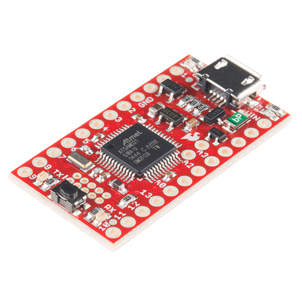
If you’re ready to step your Arduino game up from older 8-bit/16MHz microcontrollers, the SparkFun SAMD21 Mini Breakout is a great landing spot. The SAMD21 Mini Breakout is a Pro Mini-sized breakout for the Atmel ATSAMD21G18, a 32-bit ARM Cortex-M0+ processor with 256KB flash, 32KB SRAM, and an operating speed of up to 48MHz. This mini breakout provides you with an Arduino hardware option that solves the problems of low storage limits and dynamic memory stack overflows that have plagued the previous iterations of the Arduino family. Yes, the SparkFun SAMD21 Mini Breakout is even fully supported in the Arduino IDE and libraries for the Arduino Zero!
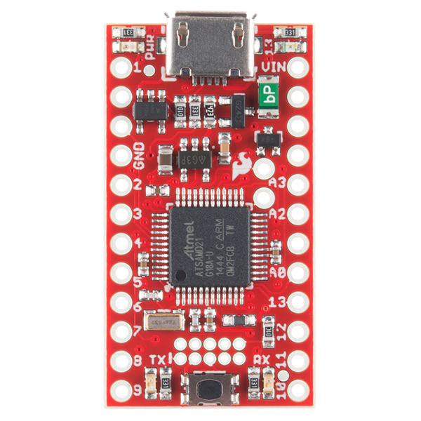
The SparkFun SAMD21 Mini Breakout has been equipped with a USB interface for programming and power, surrounded with an RTC crystal, and a 600mA 3.3V regulator. By utilizing the Pro R3’s extra PCB real-estate we've been able to leave room for a few extra GPIO pins. We’ve pinned the Mini Breakout to match – as much as possible – our faithful Pro Mini and Pro Micro. The I/O and voltage rails are all broken out to a pair of breadboard-compatible headers. Power can be supplied, and the board can be programmed, through the micro-B USB connector.
One of the most unique features of the SAMD21 is SERCOM – a set of six configurable serial interfaces that can be turned into either a UART, I2C master, I2C slave, SPI master, or SPI slave. Each SERCOM provides for a lot of flexibility: the ports can be multiplexed, giving you a choice of which task each pin is assigned.
The on-line SAMD21 Mini/Dev Breakout Hookup Guide (in the Documents section below) contains step by step instructions of how to connect your SparkFun SAMD21 Mini Breakout as well as a few circuit examples to test out. Full example code is provided and explained and even includes troubleshooting tips to make make you have zero problems.
Note: The breakout does NOT have headers installed and will need to purchased and soldered on yourself. Check the Recommended Products section below for the type of headers we use in the Hookup Guide!
- ATSAMD21G18 32-bit/48MHz ARM Cortex-M0+
- 256KB Flash Memory
- 32KB SRAM
- 32KB of EEPROM (emulated in Flash)
- 22 GPIO Count
- 14 ADC Channels at 12-bit Resolution
- Analog-to-Digital and Digital-to-Analog Converters (ADC & DAC)
- RAW: 3.5V-6.0V
- VCC: 600mA @3.3V
- Pro Mini/Micro Layout
- Integrated USB Controller
- Schematic
- Eagle Files
- Hookup Guide
- Graphical Datasheet
- Datasheet (ATSAMD21G18)
- GitHub (Design Files)
SparkFun SAMD21 Mini Breakout Product Help and Resources
RedBoard Turbo Hookup Guide
January 24, 2019
An introduction to the RedBoard Turbo. Level up your Arduino-skills with the powerful SAMD21 ARM Cortex M0+ processor!
SAMD21 Mini/Dev Breakout Hookup Guide
November 12, 2015
An introduction to the Atmel ATSAMD21G18 microprocessor and our Mini and Pro R3 breakout boards. Level up your Arduino-skills with the powerful ARM Cortex M0+ processor.
Lumenati Hookup Guide
October 12, 2017
Lumenati is our line of APA102c-based addressable LED boards. We'll show you how to bring the sparkle to your projects!
Adding More SERCOM Ports for SAMD Boards
February 4, 2019
How to setup extra SPI, UART, and I2C serial ports on a SAMD-based boards.
Stackable Headers
The 1x12 Stackable header is useful if you are testing the board on a mini-breadboard or are stacking boards underneath the SAMD21 Mini.
Cannot run program?
If you see an error like this one:
Cannot run program ... (in directory "."): error=2,
You may have skipped the step where youI was supposed to install the "Arduino SAMD Boards" before I install the specific SparkFun package.
Board dissappeared or turned into a Zero?
You can upload to this board with "Arduino/Genuino Zero (Native USB port)" selected in the IDE, however, it you do this the board will suddenly become an Arduino Zero under Windows and unless you have the Zero drivers installed, will then become an unknown device. If that happens, just install the Zero drivers located in the IDE folder and then upload any sketch to the board with "SparkFun SAMD21 Mini Breakout" selected and this will restore the board.
PWM issues on 10-13?
The PWM will not work on pins 10-13. These pins were changed around to setup the SPI in a similar fashion to the arduino form factor that we're all accustom to. You can get around this by using the "SparkFun SAMD21 DEV Breakout" definition, but if you do that, you're going to lose SPI on those pins. It should not have any other adverse effects though, and you can switch back and forth between the two definitions depending on what you need at the time.
Windows failing to recognize board?
If Windows fails to recognize the board and gives a "USB Device Not Recognized." error, try a quick double tap on the reset button to force the board into bootloader mode, and then upload some known good code like "blink."
SPI on the SAMD21
The SPI pins on the mini breakout are D10, D11, D12 and D13. Some of the older board definitions do not have it configured this way, so if you're having issues working with SPI on 10-13, you should try updating the board definitions for the SAMD21.
Core Skill: Soldering
This skill defines how difficult the soldering is on a particular product. It might be a couple simple solder joints, or require special reflow tools.
Skill Level: Noob - Some basic soldering is required, but it is limited to a just a few pins, basic through-hole soldering, and couple (if any) polarized components. A basic soldering iron is all you should need.
See all skill levels
Core Skill: Programming
If a board needs code or communicates somehow, you're going to need to know how to program or interface with it. The programming skill is all about communication and code.
Skill Level: Competent - The toolchain for programming is a bit more complex and will examples may not be explicitly provided for you. You will be required to have a fundamental knowledge of programming and be required to provide your own code. You may need to modify existing libraries or code to work with your specific hardware. Sensor and hardware interfaces will be SPI or I2C.
See all skill levels
Core Skill: Electrical Prototyping
If it requires power, you need to know how much, what all the pins do, and how to hook it up. You may need to reference datasheets, schematics, and know the ins and outs of electronics.
Skill Level: Rookie - You may be required to know a bit more about the component, such as orientation, or how to hook it up, in addition to power requirements. You will need to understand polarized components.
See all skill levels
Comments
Looking for answers to technical questions?
We welcome your comments and suggestions below. However, if you are looking for solutions to technical questions please see our Technical Assistance page.
Customer Reviews
4.6 out of 5
Based on 18 ratings:
4 of 4 found this helpful:
Excellent size
This mini breakout board is small and powerfull. Love using it.
As a note I edit the variant files on the sparkfun board to give me Serial 2 and Serial 3. Dont need them right now but good to have. I have tested these Serials and thay are working.
All info can be found on Sparkfun Forum. Link: https://forum.sparkfun.com/viewtopic.php?f=32&t=42698&p=186984&hilit=SAMD21+Serial2#p186984
1 of 1 found this helpful:
I love to hate this board...
The SAMD21 Dev Board has many unique features I need and I use it in many testers.... but it is a BEAR to develop on. It uses 2 com ports from the pc and when it's time to download, you get the error that the port you've selected can't be found :( It's there, Arduino is confused, USB ports are confused, chaos ensues. Pretty much you just have to "give in" and double tap the reset pin every down load, close your serial debug screen. Then once downloaded, re-select your port again and reopen the debug screen. I would recommend doing any simple testing of I/O using a Pro-Mini, it will go faster then switch to this when you NEED to start working on specific peripherals from the SAMD21.
1 of 1 found this helpful:
Powerful, Flexible, but is it complex
What I really like is: - with the Atmel ICE you have ability to see all the registers, variables, and set breakpoints - CPU clock, RAM, Flash, and data paths are much larger than the 8bit Mini breakout - USB included
But all the flexibility comes with complexity and frustration. Reading the datasheet is like reading a foreign language. You have a vague idea what is being described, but not enough to get you where you want to be.
I use the Atmel studio and there are major tools provided: ASF and Atmel Start. I have used both and finally settled on ASF, but it still takes a lot of experimentation to get the chip setup. Getting the clocks setup for PWM measurement and transmission was a trial.
You can find lots of example code, but there are lots of SAM flavors, and the closest example is usually for a flavor different than the SAMD21G18.
I still plan to use it as my baseline CPU board, because the power and debugging capabilities out weigh the complexity fog.
Be prepared to make a major investment in time to get to the point where you understand how to make this guy sing. Once you get past pin assignments, IO setup, and interrupt mapping, then you have all the debugging tools you expect in today's high level language development environment, and CPU resources large enough you do not ponder whether adding another variable or hunk of code is going to crash the program.
1 of 1 found this helpful:
Excellent
Works great and a nice step up from the Uno
Small & Powerfull
Very small, extremely powerful with a lot of memory. I've used this as the core component in many prototypes, it's my goto core module, it meets nearly all my needs and allows me to easily load custom HID profiles. I would love to see another variant of this, with an integrated BLE module + Li Battery charging.
0 of 1 found this helpful:
An amazingly fast and powerful board.
Incredibly fast board at 48MHz. Tons of memory for big programs. Works great with Arduino IDE, simple to load drivers.
great help for prototyping
I bought one and found it so practical the I bought 5 more. I am using it during the design phase of a complex project that supports multiple sensors. Different versions use sensors from different manufacturers. This allows me to choose the best solutions before committing the pcb. The small form factor is by far more convenient than the Atmel board.
one of the best SAMD21 boards out there!
the 4 layer PCB construction makes this board extra tiny! its the perfect balance of exposed pins and additional components.
I also like the adafruit feather M0, but it has a bunch of extra space for prototyping, and a battery charger circuit. depending on the application sometimes you dont need all the extra parts.
Great little board
I have used several of these boards in the past for various projects. These are perfect to do a quick proof of concept prior to doing a full development project for new products. The SAMD21 processor is plenty powerful enough to do most embedded tasks.
Transition From AVR to ARM
I purchased this dev board to try to get more involved with ARM programming (started with AVR). It pairs nicely with the Segger Mini Edu programmer and both integrate with Atmel Studio without a hassle. It's a little bit of pain dealing with the smaller programming header ( PRT-15362 on SparkFun) because there isn't a "key" on the silkscreen on either the breakout board or the programmer (fyi: the extruded boss on the header of the ribbon cable goes on the button side of the dev board and facing away from the IC on the Segger board; I flipped around the connector trying to program it a few times and it didn't hurt the dev board in the process). Also SparkFun has posted the design for the PCB so you can learn from them if you want to integrate this into your PCB designs.
Miserable to use with Linux
Very well built board, but utterly miserable to use with Linux. The port shows up to Arduino once in a blue moon usually after a full reset. I haven't found any clear support documentation beyond shutdown arduino and bring it back up. On one of the few occasions i could flash it I loaded a uf2 bootloader from adafruit: https://github.com/adafruit/uf2-samdx1/releases and loaded circuit python to good result
Is nice, yes
Nice product for a good price
Love this little sucker
I have both this and an Adafruit SAMD Feather. Both are great parts in different ways
I find myself prototyping with this one more because it's smaller and has the standard cortex debug port.
The near-drop-in-replacement for the ubiquitous atmega32u4 pro micro form factor has helped me as well.
Last but not least the quality of this (and other Sparkfun gear) is definitely higher than the junk I get off eBay. Big ups, thank you guys and girls!
Great product for my projects
Started out my projects using the Arduino AVR 328, but kept running out of memory. This is a great way to have access to Arduino environment and not worry about memory. I spent way too much time in the 80's dealing with memory, why do it now no 30+ years later.
what kind of current does it pull? How well does it sleep?
I tried Standby Mode using Arduino RTCZero library. I have also removed the Power LED and supplies 3.3V directly at 3.3V pin (by passing LDO). I’m getting current in range of 300uA. Considering ATsamD21 can go down to 10uA this is too much current drawn!!
Not sure if its due to Hardware of Sparkfun board or the Arduino RTCZero Library
I did some playing around. With the power LED,
SerialUSB.begin(9600), andattachInterrupt(9, cb, HIGH)I saw about 17.1mA. When I then use that interrupt handler to turn on the builtin LED (arduino pin 13) I saw about 20.3mA.I then added
EIC->WAKEUP.bit.WAKEUPEN7 = 1so that arduino pin 9 could wake the device from deepsleep. I also used a copy ofstandbyMode()from RTCZero library for putting the device to sleep. With all that I got the device to sleep then wakeup when pin 9 went high. Otherwise same setup as above, and with the builtin LED off I saw about 8.3mA and about 11.6mA with it on.Then I cut SJ1 on the back to disconnect the power LED. While sleeping, I saw about 1.3mA with the builtin LED off and about 4.8mA with it on.
Interpretations. Looks like the builtin LED uses about 3.2mA and the power LED uses about 7mA. Looking at the SAM-D21 datasheet it looks like deepsleep could be made more efficient by turning off or slowing down the peripheral clocks, but at 1.3mA I'm super happy and likely won't bother with that.
Major caveats: I'm a beginner. My multimeter is cheap and likely not very accurate. BTW, I had trouble waking the device from sleep to program it, so I wired in a second digital pin to disable sleep :)
Whats the code for sleep mode? I need help for standby and sleep mode.
The RTCZero standbyMode() actually puts the device into standby mode (also known as deep sleep). Here's its implementation: https://github.com/arduino-libraries/RTCZero/blob/c481302b6812a139d59eeb5da7d2a4cc4eefa73d/src/RTCZero.cpp#L133 For my project I have both TC4 and TC5 configured with RUNSTDBY so that they continue running during standby. Section 15.6.2.8 of the SAM D21 datasheet has lots of details.
If anyone is looking for a debug header, part# 20021111-00010T4LF from FCI looks like a good candidate. Also, I highly recommend the Atmel-ICE debugger, for those going beyond the Arduino IDE.
The integrated Lipo charger might make me use this rather than the Teensy LC/3.1/3.2 on my next project - but I so do love the teensy. It would be interesting to see them benchmarked/compared. Come on Sparkfun, how about it??
Hate to rain on your parade, this board doesn't have the Lipo charger (just the full sized version). We're updating the description now.
You can update the description but today's email from SF made the claim, so let the heads roll.
What about putting pads (underpopulated?) for the ic and stuff on the bottom near the usb? Also why are you stuck with the current board size? I mean I honestly passed by this when I first saw it thinking it was a "RedBoard mini". SFE should try to make every product unique looking in my opinion.
You could also have it on a break-away part of the board at the end (near button). That would also allow users who snap the optional pcb off to get an additional lipo charging board for other projects!
How hard would it be to have RevB include a lipo charger?
Honestly I have no idea where we'd put it. That is a pretty tight little board and is already 4 layers. I'll pass on the suggestion though.
Including the LiPo charger would be great! +1 to that suggestion :)
There is nothing on the back! Just put some pads on there to hook up the LiPo charger!
There are no parts on the back, but I see plenty of traces. There really isn't a ton of room left on there.
I have faith in the Sparkfun people. I look forward to the version with a built in lipo charger :D
[EDIT] 2/24/19 I found the messages below answering this question[/EDIT]
Apparently this board can now be run on CircuitPython. I have found lots of tutorials on how to run CircuitPython, and how to install CircuitPython. The problem is, all installations for SAMD21 boards are for Adafruit products. I have even found a .UF2 file for this exact board. What is missing is instructions on how to get this .UF2 installed on this board. It shows up as a USB device with a port assigned, but never as a USB drive. All instructions on using Arduino to install are for an .ino file that can't be found anywhere.
So, how can I install CurcuitPython on the Sparkfun SAMD21 mini Breakout?
Hi, can you explain how the Q2 p-channel mosfet works connected between USB power and Vin? Seems like just a fancy diode to ensure USB power flows only one way. I don't understand what the gate does.
MicroPython? Not the copied circuitpython ... please? Sparkfun?
Is the SAMD21 Mini breakout available with CircuitPython or MicroPython pre-installed? Or, if the python option is not available to order, which tutorial should be followed to get UF2 and python working on this sparkfun board?
Hello again! I was very mistaken in my last comment: it is indeed possible to do upload a UF2 bootloader and Circuit or Micro Python. I went ahead and added a UF2 build as well as a Circiut Python build to the SAMD21 Mini Github repo under the Firmware folder.
[DELETED]
Elias, this is great work. Thanks a million. Perhaps in future you could add support for micropython? I really dislike the CircuitPython flavor, because it actually hijacks micropython and makes it adafruit specific. Why did Adafruit not simply support MicroPython? I hope SparkFun will add support for their boards to MicroPython so the sparkfun fans are not obligated to actually use Adafruit stuff if we want to go python. The link to the github repo for the sparkfun samd21 mini breakout is: https://github.com/sparkfun/SAMD21_Mini_Breakout I will use your documentation and do the UF2 thing ... again, thanks sofar!
Hi folks, I'm Scott (aka tannewt) the lead on CircuitPython and am sponsored by Adafruit to work on it. I wanted to clarify why CircuitPython is separate from MicroPython.
The main reason is that CircuitPython is beginner focused whereas MicroPython is embedded developer focused. There are two main technical decisions that this leads to which make it difficult to share a code base: 1) CircuitPython uses properties in the hardware API whereas MicroPython avoids it because it is slightly slower than a single function call. 2) CircuitPython has a unified hardware API for all supported ports to build drivers on top of while MicroPython chooses to give ports freedom over the APIs to allow access to chip family specific behavior. More differences are documented here.
I think it's unfair to say CircuitPython hijacks MicroPython. MicroPython is open source and allows for derivatives (even closed source ones). We've always given credit to MicroPython for how awesome it is. Adafruit continues to support MicroPython's creator Damien by selling pyboards, pyboard accessories and MicroPython stickers as well. I regularly chat with Damien about technical work we're doing and offer to help integrate any changes he's interested in having in MicroPython. Renaming our fork to CircuitPython is better for MicroPython because it makes it easier to know which you are referring to. We want to see both MicroPython and CircuitPython succeed.
While the development of CircuitPython is sponsored by Adafruit, we hope to make it work well for non-Adafruit SAMD and nRF52840 devices as well. I don't feel like it's Adafruit-specific. I think its beginner-specific. We're super stoked to see SparkFun boards running CircuitPython and will continue to get the boards supported in the core repo. All devices are welcome to run CircuitPython.
MicroPython currently doesn't have SAMD21 support and adding it isn't a simple task. All of CircuitPython's code is licensed MIT so it can all be reintegrated into MicroPython as MicroPython's devs would like. So, the SAMD21 port would be made much easier by starting with CircuitPython's code.
Anyway, I hope that helps clarify things. Feel free find me on Twitter, GitHub, IRC or Discord as tannewt if you have more questions. Thanks!
You are making a good point: Support for SAMD21 is build in CircuitPython, yet not in Micropython. So it is possible for you to add SAMD21 support, yet you decided to add it to CircuitPython and not to MicroPython. That is a perfect example of the problem you have created by starting CircuitPython. These type of decisions will be made more and more. Adafruit paid developers will always favor CircuitPython right? It is rather clear: Adafruit does not have a problem using MicroPython work for Adafruits' own commercial benefit. All credits given by Adafruit to makers of MicroPython are mostly perceived as highly hypocritical. You are giving him all the praise imaginable, while at the same time you are simply stealing his work and taking away the momentum from MicroPython. Nice job Adafruit.
Agreed completely, I'll be working on Micro Python next™. I'm not entirely sure on their justification there, except that they probably wanted to determine which areas were developed themselves. /shrug. Just as a note, I didn't add a link to the repo, since its linked in the "Documents" tab above.
(Looks like that TM mark isn't rendered)
Nice to see we're on the same page. About the link...sorry I must have overlooked it in the Documents tab, my bad. Looking forward to the new developments! Thanks!
It is not unfortunately, because it does not have a flash chip on the board which is necessary for Micro and Circuitpython.
I dont see a 48Mhz crystal on the board nor in the schematics but only a 32.768khz one. Is the 48Mhz crystal internal?
I love these little boards!! I have bought at least 20 of these little buggers! they are the perfect size and power for a lot of projects. unfortunately in the last two batches i bought, four of them were missing the arduino bootloader. I was in communication with sparkfun support and confirmed this was the issue. (2 out of 8, and then 2 out of 5 of the next batch). so be careful! otherwise try to get a hold of a J-link programmer and do this manually!
I saw that this chip has a built in capacitive touch controller for up to 256 channels. Has anyone got more information about how I would use this functionality with the Arduino IDE, and even how this would be possible in terms of number of pins?
I downloaded the bootloader from github, but it doesn't build with the latest (1.8.2) Arduino toolchain. I've modified the paths in the Makefile but some fields in drivers/cdc_enumerate.c don't quite match up. It looks like you guys started with an old version of the Atmel bootloader code and then modified it. I think I can modify your cdc_enumerate.c with the code from the latest Atmel AT07175, but it might be easier to just go back to the Arduino toolchain you originally built this with. Do you remember which version of the toolchain you used?
I purchased this mini-breakout for the SAMD21 to determine if I can use it as basis of a development board for my embedded systems class. Since I want students to purchase the parts and assemble their own boards, I need them to use a Bootloader, not purchase their own Atmel ICE (they will use the department ICE once to flash the Bootloader). I ran into a lot of problems making this happen that I want to share with you so that you might not have to struggle as I did. First, the SAM-BA 2.16 utility in its current configuration is not usable, at all because it only allows you to flash .bin files starting at address 0x6000. Meanwhile, the bootloader you flash to the SAMD21 (with your ICE) assumes that the user program starts at address 0x1000 or 0x2000 depending on which you flash. You need to get yourself the SAM-BA 2.15 utility which Lars over at AVR freak generously uploaded here. *Second, since the SAM-BA 2.15 utility only allows you to flash a user program starting at address 0x2000, you will need to flash the USART/USB combined bootloader onto your SAMD21 using the ICE. This combined bootloader assumes that user program will be flashed to address 0x2000. *Third, in Atmel Studio you will need to compile your code so that it targets address 0x2000. To do this select Project -> Options -> Toolchain -> ARM/GNU Linker -> Miscellaneous and add: * -Wl,--section-start=.text=0x2000 at the end of the Linker Flags list. *Fourth, you need to ground out "pin 5" on the SAMD21 breakout when pressing the reset button. This will boot the SAMD21 into bootloader mode allowing the SAM-BA 2.15 utility to talk to the SAMD21 bootloader. I am probably forgetting several things, but this list should save you several hours. If you know of a version of the SAM-BA 2.15 or 2.16 utility that allows a user to flash to address 0x1000, I would be much obliged if you would provide a link. I hate wasting the 0x1000 bytes of memory on a kludge, but I am not in the mood to recompile the SAM-BA utility.
I added support to the Microsoft UF2 booloader for this board. See https://github.com/Microsoft/uf2-samd21 and https://github.com/Microsoft/uf2-samd21/pull/17.
You can build it with make BOARD=sparkfun-samd21-mini
Hi All, I tried Standby Mode using this RTCZero library. I have also removed the Power LED and supplies 3.3V directly at 3.3V pin (by passing LDO). I'm getting current in range of 300uA which is Okayish.. considering ATsamD21 can go down to 10uA. Can someone suggest what else I can try?
Please advice..
Does anyone have ann code for standby and sleep mode? I got the standby to work, but not able to og to sleep mode.
My Projects needs the sleep mode current to be low.
I just bought this mini breakout and I need to run 6 analog devices on it (4 gas sensors and 2 photocells). The specifications say there are 14 ADC lines, but the board only has A0 - A3 labelled. How do I get access to the other ADC lines? Where are they physically on the board and how do I reference them in the Arduino IDE? Thanks!
I am trying to write a program for this using atmel studio but the program never seems to start. I am uploading it by taking the .bin file atmel studio generates and using bossac. If i generate the bin file with the Arduino IDE, it works so theres some initialization I'm missing. Is there some startup code I need to setup?
Here is the program I am trying to run:
The power-up reset doesn't seem to work. Is this expected? If we download a simple blinky light sketch it runs as expected if the USB cable is connected. If we power the board using 5V on VIN the sketch doesn't start unless the reset button is pressed.
Adding a 10uF to GND on the reset pin fixes the problem. This seems like a bit of a band-aid though, since the SAMD21 includes a fairly sophisticated power-on reset of it's own. I'm guessing there is something a bit funny going on in the startup code in the bootloader. Will look into it later when we attempt to customize it.
Hi!How can I upload an Exported bin sketch (from Arduino IDE ) to the SAMD21 mini ?
I have Atmel Studio 7 and the Atmel Ice?Is there any particular setting ?
FreeRTOS
How easy is it to run FreeRTOS on this or the FreeRTOS port that was ported to arduino on this? Does anyone have any experience?
Downloading programs to the Mini Breakout was going very slowly, unlike my Arduino Zero. I've updated the boot loader and now the Mini Breakout downloads fast. (I can program a boot loader into a SAM D21 myself with a modified Arduino Zero board)
Is there any plan to add this to platformio? It looks like the following file will need to be updated: https://github.com/platformio/platformio/blob/develop/platformio/boards/sparkfun.json (Hmmm... it's probably more complicated than just updating that file...)
As far as I know we've never worked with these guys or heard of them, so any additions will not be coming from us. That being said, their site says it supports both Arduino and Atmel Sam chips. I haven't dug deep into that to figure out exactly what that means, but this is basically an Arduino Zero and uses an Atmel SamD21 chip, so you might be able to get it to work as is.
Makes sense. The trick with this product is that it's not an arduino zero clone (the pins and sercoms are slightly different) so platformio might have a little trouble incorporating it. Regardless, it's up to them to figure this out :) (Hopefully they have a tool to generate their configs from the arduino boards json.)
does anyone working with this mini breakout or arduino zero succeed in interfacing with low cost 0,96" or 1,3" OLED display in any combination of driver SSD1306 or SH1106 and with any graphic libraries
thanks Davide
Does anyone has a good Eagle library (.lbr) file for this nice breakout ? thanks Davide
Thanks for suggestion but I was looking more to a library components for eagle schematic and footprint for pcb I'm integrating breakout in a circuit and eagle library of the breakout helps me
You can actually find all of the Eagle parts for this board in the temp library in the product repository here.
This mini breakout board is small and powerfull. Love using it.
As a note I edit the variant files on the sparkfun board to give me Serial 2 and Serial 3. Dont need them right now but good to have. I have tested these Serials and thay are working.
All info can be found on Sparkfun Forum. Link: https://forum.sparkfun.com/viewtopic.php?f=32&t=42698&p=186984&hilit=SAMD21+Serial2#p186984
Nice little board but, increasingly, I find that such low pin count devices are becoming less and less useful for my projects especially with all the pin sharing current microcontrollers do. By the time you use a few of the on-board peripherals you end up with very few/no GPIOs. Teensy 3.2, the Pro Mini, this board all fall into this category. I love Teensy because of it's M4 processor but the board layout/pinout is a challenge.
Anyway I'd find this board much more attractive if it used a ATSAMD21J18 and was lengthened to accommodate the additional pins (8 per side). The 16 additional I/O's would make it much more flexible and useful for a larger number of projects. Is there a marketing reason backed up by actual data that says you have to stick to so close to the Pro Micro /Teensy form factor ?
For me it is very useful this product uses the same layout as the pro micro! More pins are available on other boards, but those are ... other boards.
In the graphical datasheet, PA14 is marked as I2C-capable. However, the Atmel datasheet does not mark this pin as I2C-capable. (It seems no PAD2 or PAD3 pins are I2C capable, actually.)
Does this board support an external analog reference when using the Arduino IDE? When I try the following: analogReference(EXTERNAL); I get an error: "invalid conversion from 'int' to 'eAnalogReference"
The correct form is: analogReference(AR_EXTERNAL); There needs to be an AR_ prefix attached to the various analog reference modes.
Ordered two of these, and although I'm not 100% sure, it looks like the SPI port that is implemented is not the default one that is used by the Arduino IDE.
The Zero schematic suggests that the SPI port on pins: PB10, PB11 and PA12 is the default. Perhaps someone can confirm?
Also, the RX/TX map to what is essentially the "second" serial port; SERIAL1. PB22 and PB23 are the default SERIAL0. The schematic suggests that SERIAL0 is connected to the EDBG header, but it's not clear which pins would be used.
Correct on all fronts. This board doesn't break out the default Arduino SPI pins (those on what would be the ICSP header of an Arduino Uno). Instead the SPI port is mapped to pins 10-13 (SS, MOSI, MISO, and SCK, respectively).
PB22 and PB23 are also not available, and the pin 0/1 RX and TX are assigned to the
Serial1object.What spacing are the 5x2 header pins? What is the part number for Break Away Headers for the 5x2 pins?
All the headers in the referenced document are .1 inch spacing and the 5x2 arrays appear much smaller than .1 spacing.
The debug header is 0.05"-pitch. This section of the Hookup Guide has a bit more info on the connector and recommends a header.
I have the SD card connected with pin 9 as the chip select. Sam won't initialize the card. All I did was pop out the pro mini 3.3v and popped this in the board. Code compiles and downloads but won't initialize card. The pro mini had no issues with the SD on my board.
The SPI port doesn't default to pins 10-13 on the SAMD Mini like it does on the Arduino Pro Mini -- that's probably what's causing the issues. Luckily there is an unused SERCOM port on those pins, so we should be able to make it work.
We've released an updated Arduino board package which adds an additional board definition for the Mini boards, equipping them with SPI on pins 10-13. If you go to your Arduino Board Manager, and click "Update" on the "SparkFun SAMD Boards" package (you may have to open and close the Board Manager twice), that should add the extra "SparkFun SAMD21 Mini Breakout" option on the boards menu. Try uploading with that board selected -- seems to be working for me with an SD card.
Cool news!
I was looking though the "variant" files for the SAMD21 mini breakout and I can't see where the re-mapping was done (it all appeared to be Zero defaults). Can you show us how the remap was done?
Maybe I'm looking at the wrong package...
Yup, it's just a few-line change here in Variants.h.
Ah! Got it, must have been looking at the wrong file...
Is it possible to re-map the Serial0 UART to any of the other available pins to allow two hardware UARTs and SPI/I2C? (realizing that this reduces available pins pretty far!)
I'm curious about the overhead/efficiency of the power regulation on board. Will this work if I plug a lipo (3.7-4.2v) into VIN? Does it have the same DC-DC converter and LDO voltage regulator pair that the Zero has?
Basically I want to run this for 7 days from a 2500mAh lipo, which I think works out to an average current of 13mA. I'm hoping to make heavy use of standby mode to accomplish this, but I'm worried about "station keeping" components such as the regulator(s).
The regulator we use on this is the ap2112k. I'm not sure what setup the Zero uses, but its probably not going to be exactly the same. Feel free to check out the schematic (in the documents section) or the datasheet for ap2112k.
Unfortunately, the SparkFun SAMD21 Mini Breakout doesn't breakout the SPI header, used by the arduino SPI library.... :-( What about that ?
Our Arduino board definition for the Mini Breakout assigns SPI to pins 10-13 -- similar to the signal pinout on ATmega328-based Arduinos (10=SS, 11=MOSI, 12=MISO, 13=SCK).
I wish I had known about this a couple of months ago! :) I am totally going to start using this Micro in all of my projects, especially since it has 256K of storage space and hardware serial on different pins.
Hrm, I was hoping this would be a step up from the Teensy 3.2, but it seems to fall a bit short instead. Mainly in terms of RAM (half) and CPU speed (2/3)
This would be an awesome board to have a one or two 5V outputs (similar to the Teensy LC, but the 8k ram is too limiting for many of my needs), so that you don't need separate level shifters when using 5V hardware like WS2811 LEDs.
It's really cool. What about the bootloader? Is it necessary upload a previous bootloader to the ATSAMD21G18? Thanks!
We program a bootloader on it here, when we build the board. All you need to program it is a USB cable!
Yes, but...Is it opensource? Where can I find it? I've been checked the Git repository, but without luck.
We could probably find a better home for it. For now it's in our Arduino_Boards repo. I'll see about getting it in the individual boards' repo's.
Love the board! We're using a bunch of them in a project for a lab here. We'd like to customize the bootloader as we have the boards on a shared serial bus and would like to be able to add some sort of addressing scheme.
I'd prefer not to buy IAR tools. I notice the stock Arduino Zero bootloader can be built with gcc/make. Can the customized sparkfun one be built successfully with open-source tools? Or, is there a list of patches against the Arduino Zero one?
We can sort this all out ourselves given time (and eager students) but if you guys have any suggestions it would be great.
Great. SparkFun is awesome! Thank you.
Very interesting, this will really help in creating one's own ARM solutions and provides a solid base to build those on. Thanks SFE!
This is awesome! Would have loved to have had this for a project I was working on a few years ago.