- Home
- Product Categories
- Raspberry Pi HATs
- RS485 Shield V3 - Raspberry Pi


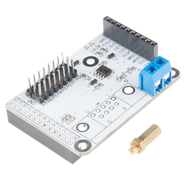
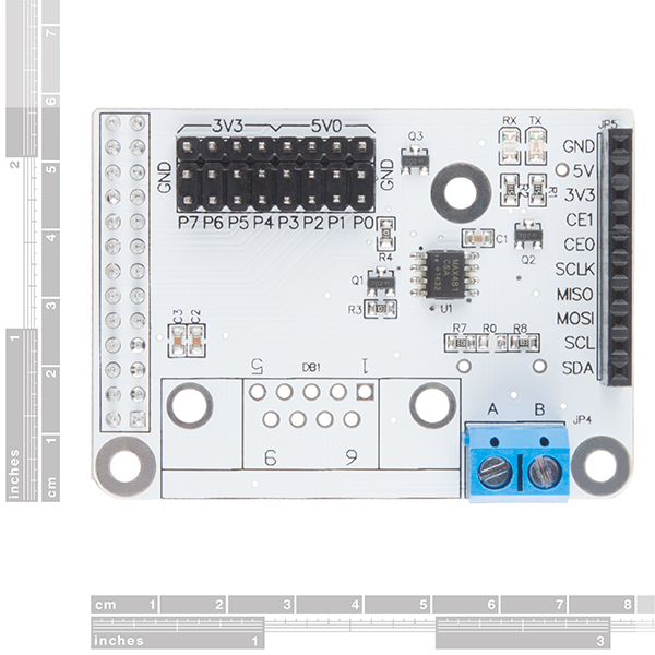
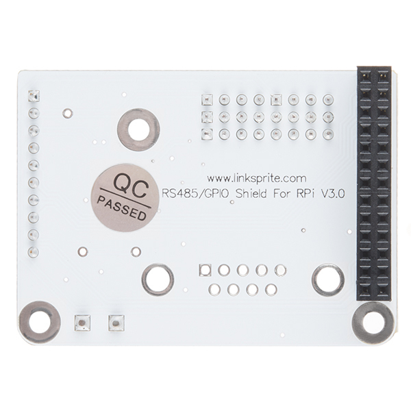
RS485 Shield V3 - Raspberry Pi
Our friends over at LinkSprite have made this nifty little RS485 Shield V3 for the Raspberry Pi, now you will be able to have a communication port for your field bus directly connected to your RPi! Even though the RS485 is sometimes thought as an "archaic" protocol, it will allow up to 32 devices to communicate through the same data line over a cable length of up to 4,000ft with a maximum data rate of 10Mbit/s. Those aren't bad numbers!
This shield comes pre-assembled so all you will need to do is just snap it right onto your Raspberry Pi and get programming. The RS485 Shield V3 is compatible with Raspberry Pi B, B+ and Raspberry Pi 2.
Note: The shield has an unpopulated footprint for a DB9 connector. Check below if you need to add the connector. Otherwise you can use the screw terminals.
- Schematic
- Datasheet (MAX481CSA)
- User Guide
- Product Wiki
RS485 Shield V3 - Raspberry Pi Product Help and Resources
Compatible with the Pi3
The RS485 should work with the Pi 3. Looking at LinkSprite's user guide for RS485 Shield V3, there is a note that it is compatible with the Raspberry Pi 3 => http://linksprite.com/wiki/index.php5?title=RS485/GPIO_Shield_for_Raspberry_Pi_V3.0 . You might need to do some modifications to get it working however => http://www.briandorey.com/post/Raspberry-Pi-3-UART-Boot-Overlay-Part-Two. This comment is in the manufacturer's product page.
Core Skill: DIY
Whether it's for assembling a kit, hacking an enclosure, or creating your own parts; the DIY skill is all about knowing how to use tools and the techniques associated with them.
Skill Level: Noob - Basic assembly is required. You may need to provide your own basic tools like a screwdriver, hammer or scissors. Power tools or custom parts are not required. Instructions will be included and easy to follow. Sewing may be required, but only with included patterns.
See all skill levels
Core Skill: Electrical Prototyping
If it requires power, you need to know how much, what all the pins do, and how to hook it up. You may need to reference datasheets, schematics, and know the ins and outs of electronics.
Skill Level: Rookie - You may be required to know a bit more about the component, such as orientation, or how to hook it up, in addition to power requirements. You will need to understand polarized components.
See all skill levels
Comments
Looking for answers to technical questions?
We welcome your comments and suggestions below. However, if you are looking for solutions to technical questions please see our Technical Assistance page.
Customer Reviews
4.8 out of 5
Based on 5 ratings:
1 of 1 found this helpful:
Works great!
I've just tested this on a Raspberry PI 3, and it works great!
Just keep in mind that the latest version of Raspbian has removed the UART from the gpio on raspberry pi 3, so you need to put it back using a device tree overlay.
I am using it with a modbus device at 115200 with no problems.
Works perfect
Everything works fine - i recommend
Nice converter
Works !
Is it possible to use this header with a raspberry pi zero w?
I can't access the user guide or the Wiki. It appears LinkSprite is down. Are you able to send the user guide over or publish it on your site?
I may be missing something, but from my reading of the MAX481 datasheet the device needs a VCC of 5V. The schematic of this board shows VCC supplied by 3.3V. Does this really work?
Will this shield be able to communicate with a device over modbus rtu - like the existing USB to rs485 USB dongles?
Hi Guys,
sorry if the question is stupid to you but I'm still in the phase of deciding if to use or not raspberry PI for the application I need to develop.
The scenario is the following: 32 RFID UHF readers needs to send data to the raspberry PI.
Existing readers have RS485 protocol and I cannot change them. I was looking at this RS485 shield. RS485 supports up to 32 devices. And this is ok. My problem is that I NEED to be able to know which is the device sending the TagID! There is no way to program the RFID reader to send a prefix, so, my question is: when on the raspberry I will receive data from the GPIO SHIELD there will be a way to know which is the particular device sending the tag id?
Hi I'm curious about one thing. The RXD is directly connected to the Ras. Pi. Is this good ? The MAX481 chip is powered by 5V, so won't RXD have 5V when logic 1 ? The Ras.Pi Ports are only 3.3V tolerant. How does this work without damaging the RXD GPIO of the Ras.Pi ?
This design is not helpful for multi drop RS-232 networks. The transmit enable and receive enable-not are tied together and controlled by the transmit pin. This is fine for simple point to point networks. With this configuration you can't properly determine if you had a collision on the bus should two devices try to talk at the same time. The solution is to always enable the receive buffer and only enable the transmit when the mode wants to transmit. In this way to receive the bytes you transmit. If those bytes are identical, you had no collision. If they are different you did, and your software can take appropriate actions to re transmit the data. You have had the same problem with all your 485 devices. And each time I use one, I have to cut lift a pin and tie it low. Could you at least not have put in a solder jumper as I suggested in a similar comment for your other 485 BOB?
As plagued the previous versions, the data direction is controlled by the Tx line of the RPi, and without a capacitor. Therefore it will only transmit the zeros, not the ones. Theoretically you could add in a capacitor to maintain transmitting, but then it might hold control of the bus for too long (it would depend primarily on the baud rate, but also on the data itself).
Unless I'm missing something in the schematic, this is a very serious issue.
What I personally decided to do was use a separate GPIO to control the direction. It works fine, but requires software to determine when it has finished transmitting, to control the direction. I did this in C, but it should also be possible with python.
Is the 32 device limit a hard limit or can you get 33~35 devices on the bus and still probably be OK?
The datasheet states 32 due to the impedance of the MAX481 (it isn't an arbitrary number). In my experience with the MAX485 (almost identical) there is a lot of room for things not being perfect. RS485 is significantly over-engineered for most applications, making it extremely robust. I don't think you'll damage anything using 35 devices, but being out of spec, I wouldn't guarantee anything either.
If you need more than 32 devices, and want to remain in spec, check out the MAX487 or the MAX1487, with similar specs, and a maximum of 128 devices (those and others are in the datasheet linked to above).
Awesome explanation MatthewR, Thanks!