- Home
- Product Categories
- WiFi
- SparkFun ESP8266 Thing - Dev Board

SparkFun ESP8266 Thing - Dev Board
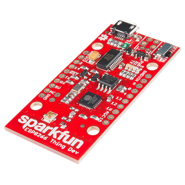
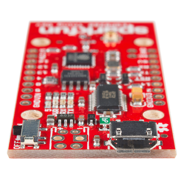
This is the SparkFun ESP8266 Thing Dev Board – a development board that has been solely designed around the ESP8266, with an integrated FTDI USB-to-Serial chip. The ESP8266 is a cost-effective, and very capable WiFi-enabled microcontroller. Like any microcontroller, it can be programmed to blink LEDs, trigger relays, monitor sensors, or automate coffee makers, and with an integrated WiFi controller, the ESP8266 is a one-stop shop for almost any Internet-connected project. To top it all off, the ESP8266 is incredibly easy-to-use: firmware can be developed in Arduino, and uploaded over a simple, serial interface. The ESP8266 Thing Development Board breaks out all of the module’s pins, and the USB-to-serial converter means you don’t need any peripheral components to program the chip. Just plug in a USB cable, download the Arduino board definitions, and start IoT-ing.
Why the name? We lovingly call it the “Thing” due to it being the perfect foundation for your Internet of Things project. The Thing does everything from turning on an LED to posting data, and can be programmed just like any microcontroller. You can even program the Thing through the Arduino IDE by installing the ESP8266 Arduino addon.
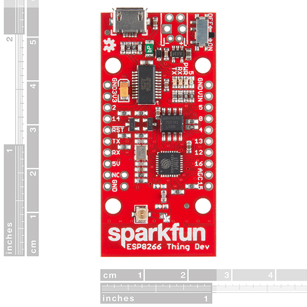
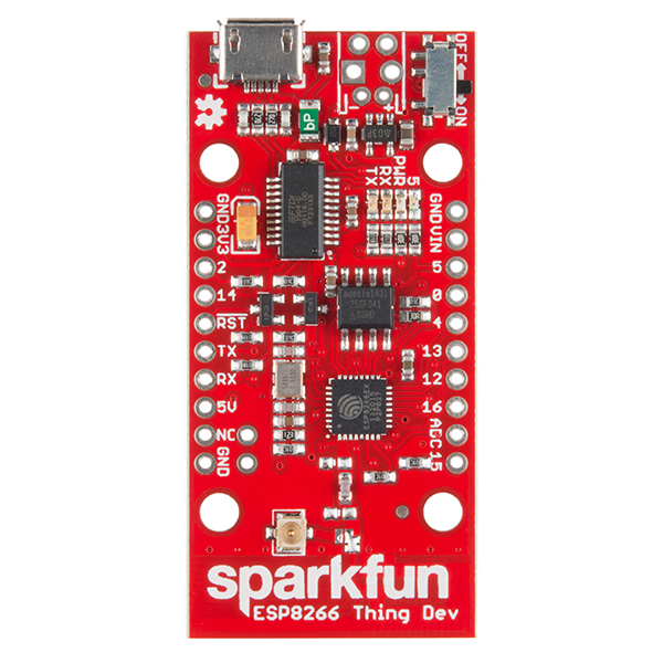
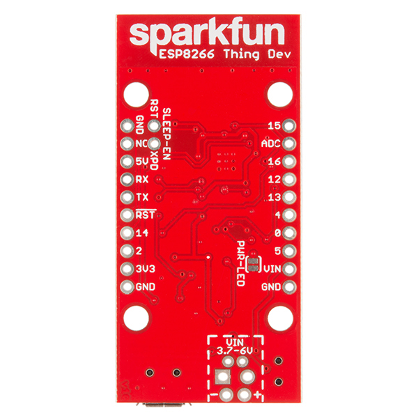
The ESP8266 Thing Development Board is a relatively simple board. The pins are broken out to two parallel, breadboard-compatible rows. The USB connector sits next to an optional power supply input, and an ON/OFF switch – controlling power to the ESP8266 – sits next to that. And LEDs towards the inside of the board indicate power, charge, and status of the IC. The ESP8266’s maximum voltage is 3.6V, so the Thing has an onboard 3.3V regulator to deliver a safe, consistent voltage to the IC. That means the ESP8266’s I/O pins also run at 3.3V, you’ll need to level shift any 5V signals running into the IC. If your project requires a power source other than USB, the Thing Dev Board includes footprints for a 2-pin JST, 2-pin 3.5mm screw terminal, or a simple 0.1"-pitch 2-pin header. This board has 4Mbit SPI (512KB) on board flash memory. Unlike the original ESP8266 Thing, the ESP8266 Thing Dev Board does not have a built-in LiPo charger.
The Thing Dev Board even includes a PCB trace antenna as a default WiFi antenna, it’s cost-effective and actually works really well! If you need to connect a more sensitive antenna, or need to route outside an enclosure, a U.FL connector is also available on the board. Some soldering will be required to get the U.FL connector functioning but instructions can be found in the Hookup Guide we have written for the dev board.
Note: We've provided a few Example Sketches to experiment on your SparkFun ESP8266 Thing Development Board. These sketches can be found in the Hookup Guide in the Documents section below!
- All module pins broken out
- On-board FTDI USB-to-Serial
- 802.11 b/g/n
- Wi-Fi Direct (P2P), soft-AP
- Integrated TCP/IP protocol stack
- Integrated TR switch, balun, LNA, power amplifier and matching network
- Integrated PLLs, regulators, DCXO and power management units
- Integrated low power 32-bit CPU could be used as application processor
- +19.5dBm output power in 802.11b mode
- Schematic
- Eagle Files
- Hookup Guide
- ESP8266 Powered Propane Poofer
- ESP8266 Community Forum
- GitHub (Design Files)
- GitHub (Arduino Library)
- Graphical Datasheet
SparkFun ESP8266 Thing - Dev Board Product Help and Resources
ESP8266 Powered Propane Poofer
March 15, 2016
Learn how Nick Poole built a WiFi controlled fire-cannon using the ESP8266 Thing Dev Board!
LED Cloud-Connected Cloud
February 22, 2016
Make an RGB colored cloud light! You can also control it from your phone, or hook up to the weather!
LuMini 8x8 Matrix Hookup Guide
January 24, 2019
The LuMini 8x8 Matrix (APA102-2020) are the highest resolution LED matrix available.
ESP8266 Thing Development Board Hookup Guide
November 5, 2015
An overview of SparkFun's ESP8266 Thing Development Board - a development board for the Internet of Things.
Choosing an Arduino for Your Project
December 11, 2017
Examining the diverse world of Arduino boards and understanding the differences between them before choosing one for a project.
Using Flask to Send Data to a Raspberry Pi
November 9, 2017
In this tutorial, we'll show you how to use the Flask framework for Python to send data from ESP8266 WiFi nodes to a Raspberry Pi over an internal WiFi network.
Introduction to MQTT
November 7, 2018
An introduction to MQTT, one of the main communication protocols used with the Internet of Things (IoT).
Internet of Things Experiment Guide
November 23, 2016
The SparkFun ESP8266 Thing Dev Board is a powerful development platform that lets you connect your hardware projects to the Internet. In this guide, we show you how to combine some simple components to remotely log temperature data, send yourself texts and control lights from afar.
Three Quick Tips About Using U.FL
December 28, 2018
Quick tips regarding how to connect, protect, and disconnect U.FL connectors.
Using Home Assistant to Expand Your Home Automations
May 9, 2019
An introduction to Home Assistant, an open source home automation hub.
0 of 1 found this helpful:
I2C location.
The silk screen on the left side is for I2C -- it says GND, 3V3, 2, 14. Pin 2 is SDA and Pin 14 is SCL.
1 of 1 found this helpful:
LED acting strange?
The LED5 is reversed from the ESP8266 Thing (not dev) version. The LED is pulled HIGH -- so, a LOW turns it on, and a HIGH turns it off. This was done because it matches the datasheet for the ESP8266 so that the LED could be used as a WiFi indicator.
Core Skill: Soldering
This skill defines how difficult the soldering is on a particular product. It might be a couple simple solder joints, or require special reflow tools.
Skill Level: Noob - Some basic soldering is required, but it is limited to a just a few pins, basic through-hole soldering, and couple (if any) polarized components. A basic soldering iron is all you should need.
See all skill levels
Core Skill: Programming
If a board needs code or communicates somehow, you're going to need to know how to program or interface with it. The programming skill is all about communication and code.
Skill Level: Rookie - You will need a better fundamental understand of what code is, and how it works. You will be using beginner-level software and development tools like Arduino. You will be dealing directly with code, but numerous examples and libraries are available. Sensors or shields will communicate with serial or TTL.
See all skill levels
Core Skill: Electrical Prototyping
If it requires power, you need to know how much, what all the pins do, and how to hook it up. You may need to reference datasheets, schematics, and know the ins and outs of electronics.
Skill Level: Rookie - You may be required to know a bit more about the component, such as orientation, or how to hook it up, in addition to power requirements. You will need to understand polarized components.
See all skill levels
Comments
Looking for answers to technical questions?
We welcome your comments and suggestions below. However, if you are looking for solutions to technical questions please see our Technical Assistance page.
Customer Reviews
4.1 out of 5
Based on 71 ratings:
2 of 2 found this helpful:
These Things are Great!
These things are perfect for small WiFi connected projects. I've bought several of these and am using them for:
- Remote thermometer (posts temp data to wunderground.com)
- Solid-state relay controller (for holiday lights)
- Mechanical relay controller (for outdoor and holiday lights)
With the latest Arduino update, you can easily program these things with the IDE. They're a little more expensive than the bare-bones ESP8266 modules (I have some of those to), but the integrated FTDI, the 5V->3.3V regulator, and many more I/O pins make this a much better option unless you're building a bunch of units.
5 of 5 found this helpful:
ESP8266 Thing working with Blynk
I placed my ESP8266 Thing into a two gang electrical outlet box with a five volt double relay board and connected the high side of the relays to control my garage heater thermostat contacts and the power line 110 volts to the heater respectively. I also connected a TEMP36 temperature sensor to the Thing ADC pin. I glued a small wall wart inside the box to power all the low voltage needs. The relay on the 110 volt power line is there to allow the heater to be disconnected entirely from the electrical grid - it helps to isolate it from nearby lightening strikes and related damage. I used the Blynk library in my Arduino IDE and programmed the Thing as easily as an Arduino UNO. I then made the Blynk Android app for my mobile phone in no time at all. The Blynk app is child's play. Now I can view my current garage temperature from anywhere. I can decide to connect the garage heater to the power grid. And lastly, I can set a Blynk slider control on my phone to set the garage temperature and the Thing connects the thermostat contacts to heat the garage until the desire temperature is reached. Sweet.
15 of 15 found this helpful:
Nice board except the Flash memory is too small for OTA updates
These boards only have a 4Mbit SPI flash and not the 32Mbit one that other ESP8266 development boards, like the NodeMCU using an ESP-12E module. Only having a half MByte of flash means that you can't perform Over The Air (OTA) updates. I have several of the Things (both Dev board and not) and some other ESP8266 boards based on ESP-12E modules, including several of the NodeMCU boards which are about the same price as a Thing. I've put together four projects so far using these boards and the Blynk app promoted by SparkFun and have been very happy with the results. I heard that OTA updates were possible with an Arduino based ESP8266 and I have recently figured out how to do it using the NodeMCU boards which have 4MByte of flash. The OTA implementation is very simple and involves only adding a little extra code to every sketch. A USB connection is used once to load the initial OTA-enabled sketch and all updates after that are OTA and are incredibly fast (compared to 115kbaud) and can be done from anywhere there’s an internet connection (assuming you can see the device on the internet). I used my NodeMCU boards to get the OTA figured out because the instructions said I needed to use a board like the NodeMCU with a large flash. I checked the schematic for the Thing and visually verified the chip number (ATSF041) is only a 4Mbit flash part. I don’t recall seeing any vendor make a point of how large their flash memory part is and since many ESP boards have a metal can over the ESP8266 and the flash you can’t look at the part. I am surprised that there is not more mention of the difference in flash size between ESP8266 development boards, but I guess that shows how new this is to all of us. Having a 4MByte flash is great for doing OTA but also having an Arduino with that much flash available takes away the worry (for a while) of running out of code space. The OTA implementation also reserves the top 1MByte for a spiffs file system accessible from the Arduino code, along with the two 1.5MByte partitions to do the OTA in. I think SparkFun should immediately start loading the boards with 32MBit flashes and alert people to the fact that there is only a 4Mbit part on the current boards. I’m sure that there will be a price increase for the boards, small I hope, but when developers start getting wind of how cool, easy and fast it is to do OTA updates on an Arduino, they are not going to want to give it up.
1 of 1 found this helpful:
Very cool for the pricepoint! Easy to setup and use
After setting up the libraries, I was able to remotely monitor and manipulate objects in my office in minutes using the IoT Hobby Kit Experiment Guide. https://learn.sparkfun.com/tutorials/iot-hobby-kit-experiment-guide
I look at this as a great low-cost option for adding wireless network access to existing projects, and it also has enough memory and I/O to use as a standalone board for simpler projects.
So far so good with the hardware reliability. I purchased 3 units on Cyber Monday and all 3 are working nicely to date.
9 of 9 found this helpful:
Makes a great remote device sensor
With the clothes drier in the basement and the living area two floors up combining it with a torroidial coil around one phase of the drier power cord and a rectifier and filter circuit to feed the analog input I can now hit the onboard web server and see if the drier has stopped running without going up and down stairs.
1 of 1 found this helpful:
Pretty slick little dev board!
This board is great! It gives super-simple access to tinkering with the ESP8266 chip. If it weren't for a bug in the Arduino IDE, I would have been posting to phant.io 20 min after opening the box. It makes the bar for prototyping with ESP8266 really low.
1 of 1 found this helpful:
Awesome WiFi Package
I purchased the Thing Dev Board to use in a project I have, which will gather environment data from sensors, then send that data up to my database, to be graphically represented on a website. The first board I received bombed. I could see the board via the Arduino IDE, but I could not transfer any data to/from it. This is where the story gets good... I turned to Sparkfun tech support. These guys/gals are awesome! I was walked through several troubleshooting scenarios, and eventually sent my board back to the tech support rep, so that he could duplicate and discover what the root problem was. Tech support found my board to be a dud, and sent me out a replacement most riki-tik, complete with headers installed. This new board is flawless, and really does have an impressive WiFi range. Even though my first board was a brick, Sparkfun tech support was so impressive that I have to give 4 stars for the review. If this was a review of tech support only, I would give six stars, er, okay, five stars!!
2 of 2 found this helpful:
Temperature Humidity Logger
I used this board to make a temperature humidity logger for a crawl space under a house. It works great! I posted the project here: https://hackaday.io/AlanCampbell
4 of 4 found this helpful:
Great tech if you want a shortcut to I/O control from your phone
I purchased this so that I can start projects that are controlled through my cell phone and was intrigued by the Blynk App.
I decided my first project was going to be to control a lamp in my living room. The challenge I found with this was not about the chips but about putting all the components in a box. I hooked it up to my computer, took me a few tries to get the driver install right, and then I was off to the races. installed the Blynk software and after fiddeling with the syntax for my router got it connected. Probably 45 mins from pulling out of the box I was blinking the LED.
I purchased 2 of these because I invariably manage to let the magic smoke out of my project boards. This is no exception. I tried to hook it up to a 12V power supply and POOF. then i noticed the big white letters on red background on the back side that said Vin 3.7-6.0 Volts.
WIth the destruction of my first board complete, I loaded my software on the second board and connected a pin to control the relay. I found that the pin will randomly drop out .
I next hooked up the Thing to control my Uno with 2 pins one acting as an on switch and the other as an off switch. As a result, my light doesn't flicker every 15-30 minutes anymore, but the blynk app does not allow for one button to control 2 switched (at least I haven't found it).
My next project is to use this board to control a Ceiling fan.
1 of 1 found this helpful:
not enough memory
only 512k... worst esp8266 board on the market in terms of memory: https://github.com/esp8266/Arduino/blob/master/doc/filesystem.md#flash-layout
I actually tried to find the flash memory before I bought 15 for my class but couldn't locate that information anywhere.... so I found out the hardway.. I wanted to host a simple javascript page to show some buttons.. I'll have to really skimp to make it under 64k... not the definition of a development board.
Here's a bunch of micro JS libraries that should help me get the job done... http://microjs.com/#
You're correct, with only 512K, there is not a lot of flash memory on these for larger programs. Sorry this didn't work out for your needs. Please contact us if you would like to request a return. www.sparkfun.com/returns
5 of 5 found this helpful:
Awesome!
I love this thing! It breathed new life in to my Arduino project dreams. I used this to create a web-connected thermostat. I considered a Raspberry Pi, but it seemed like so much overkill. So I tried it with Arduino on this board and it works awesomely. I just wrote a little web server to respond restful-y to http requests, threw in a temperature sensor and a relay, then created a little web gui to hit the endpoints. Lovin' it!
1 of 1 found this helpful:
Love the Thing!
This is a very fun board to experiment with. The WiFi is powerful, I see it all over my house(2600 sq feet house) Very easy to program it. I just love it!
1 of 1 found this helpful:
Excellent for teaching
I used this board to teach IoT classes at TinkerMill. It is awesome because all that is needed is a USB cable to work with it, which makes it very easy for beginners to use.
9 of 9 found this helpful:
Had to wire GPIO0 to Ground to program
Thanks to the reviewer who advised connecting DIO 0 to ground and power cycling to put the chip into bootloader mode. I kept getting "error: espcomm_open failed" until I did that. Tried changing cables, and devices, but that did the trick!
7 of 8 found this helpful:
Programming requires manually setting GPIO to ground on power up (EDIT: fixed with Arduino 1.6.7 + ESP Arduino 2.1+)
We ran a workshop with 25 of these boards and no one (users on windows, mac, and linux using instructions from the latest hookup guide) could program their ESP8266 Thing Dev without turning it off, hooking GPIO0 to Ground and then turning it back on. It seems that the FTDI chip sequence to take GPIO to ground and then reset the board to put the chip into bootloader mode didn't work. Other than that inconvenience, it seemed to work well. It just slowed us down a lot. Some participants hooked up a switch between ground and GPIO so that they could more easily turn on "programming" mode.
EDIT:
This appears to have been a software problem. It now works on OSX with Arduino 1.6.7 and the ESP Arduino 2.1+.
I believe it was a change with the ck reset vs. nodemcu reset style.
1 of 2 found this helpful:
Not enough output current
I want to drive a NeoPixel strip with this but just can't seem to get it to work (I had success with most of the tutorials). I think the gpio output current is too low to drive neopixels. Has anyone had any success in this regard? EDIT: I have subsequently been successful using a cheap ESP8266 ESP-12E module to drive a NeoPixel strip, so I am going with that.
2 of 4 found this helpful:
Doesn't seem to work.
So far I can't seem to get the ESP8266 Thing to work. The board definitions for the Arduino IDE won't even download on OSX because of SSL errors. I can get the blink sketch to work on Linux, but no internet connectivity. In contrast, I was able to get a Photon board up and running on my local network, so I know this isn't a network issue. It seems that the ESP8266 ThingDev is still too experimental and buggy. I wouldn't recommend it except as a project in and of itself. I would recommend the Photon instead, (provided you have a recent smartphone).
Easy to use and can run Firmata
I flashed it with Firmata, to be exactly, StandardFirmataWiFi sample code. And then my PC can start controlling the board over Wi-Fi via Johnny-Five (Node.js). Except Firmata + J5 takes some time to talk to each other (15-30 seconds), everything is good.
It seems some of the pins (GPIO0, GPIO2 and GPIO15) should not be touched before the device boot up. Otherwise, the board will go into different boot mode and stop running my code.
I read an article and it say to keep the board booting normally, GPIO15 should be kept low while GPIO0 and GPIO2 should be high.
Compare to Arduino, the board comes with less GPIO pins and weird pinouts (many GND pins and GPIO pins not sorted).
The on/off switch is very handy. With the switch set to off, I can plug in the board and got the COM port on my PC, while keeping the board off. So it's very handy to restart just the code on the board.
It also supports Azure IoT Hub and I am sure to try out later.
ESP8266 Thing Dev Board
I got this board to work with the Arduino IDE 1.6.8 by also loading the ESP8266-Thing Dev board extensions in Linux. I am running Mac OS X Version 10.5.8 on a Mac that I purchased in 2008. Processor 2.2 GHz Intel Core 2 Duo with $GB 667 MHz DDR2 SDRAM. It is running in a Virtual Box created by VMware Fusion Version 1.1.1 (72241), that I also purchased in 2008. The USB extensions seem to work just fine. However, I tried Virtual Box and it runs much slower and has many problems with USB. It would be nice if the ESP8266 chip they put on this board is one of the newer ones with much more Flash Memory. The AP app take almost half of the available Flash Memory. I have also purchased an an ESP8266 ESP-1 module. I am looking how to connect the Sparkfun Beefy 3 -FTDI Basic Breakout board to it.
Great Board
The ESP8266 Thing - Dev Board is terrific. My first board had a defective LED, which initially lead me to believe that I couldn't program the board since I couldn't get "blink" to work. Once notified, Sparkfun immediately sent me a new board; kudos to them. The original board works fine; just no LED.
Very good, web server up in 30 min
This board integrates nicely with the Arduino ide. My project, a small web server, was up and running quickly and without difficulty.
I wish it had an additional AD converter input, and I wish there was better documentation about the different modes available (I think) and what the trade offs are. For example can I switch modes in the program. I'm also a bit confused about the memory types and sizes available and how to access it. .
Great Product
Very compact.
All connections brought out to pads.
FTDI interface on-board.
Build quality good.
Works out of the box!
Cool little board
Bought two of these boards. Got one working very quickly. Paired with a multi-sensor board, I now have a pretty cool mobile temp/pressure/humidity sensor that allows me to take long duration readings from anywhere around the house. Lots of possibilities with this board.
Haven't figured out how to query things like the WiFi's signal strength yet. That would be really nice to know.
Bought two boards. One board is flaky - the USB connector is sensitive to the slightest movement. Probably not worth the shipping cost to have it replaced. Oh well.
Sorry to hear that one of the boards was a little off. We'll take care of that for you!
Very small memory
This device seems to work fine but the product details are missing a crucial bit of information: the board only has 512KB of flash memory. This severely limits its utility if you want to do anything like store images or patterns to flash out on LED panels since you will rapidly run out of room. It also makes it unsuitable for using high level programming tools like MicroPython.
This is the "dev board" version; it would be nice if the product details gave you a few more details about the product...
Thing Dev board, easy to get statrted
I purchased the Thing Dev board to learn about the ESP8266. This board was easy to get up and running right out of the box. My only problem was an sub-standard cable. I should have purchased a new cable from Sparkfun when I purchased the board. This is an easy way to get your IoT project onto the Internet fast.
"Really Cool"
Programming the dev board is easy via the USB port. Out of the box, it ran 4 days on two AA batteries, while logging temperature and humidity data once per 15 seconds to ThingSpeak. With easy optimizations, like low power, sleep modes, less frequent logging, and others, this board can run several times as long. I have had no problems with the WIFI connectivity. However, upon arrival, the orange thing (capacitor maybe?) next to the FTDI IC was chipped enough to show the inside of the component. As far as I know, this does not affect performance. I'm sure such an issue is very rare and it does not impact the usability.
First and subsequent impressions: VERY GOOD
Update, March 2019-
Still very happy with this. Yes, you can buy "an ESP8266" for less. Yes, there are ESP8266's out there with MORE memory. (This one has enough for what I've wanted to do so far.)
But I'm happy to "pay the price": I KNOW the Saprkfun device will WORK. It has great support documentation on the Sparkfun site. There are no dramas or ridiculous "p&p" charges when you buy from Sparkfun. You can gt lots of things from one source.
Want more memory? (And fater proc(?), more features, etc... I haven't tried it yet, but will order one soon and hope time to "play" with it comes soon: For $3 more, you can have the relatively new "SparkFun Thing Plus - ESP32 WROOM", WRL-14689
For months now I've had one of the devices this review is about monitoring two temperatures... and making them available to the internet. That Arduserver (see http://ArduServer.com) has had the same software running all that time. Just recently, I have also started looking at the values in two counters it maintains (using the device's built in hardware to count pulses on an iinput) and the value that reflects the state (high or low) of ANOTHER pin. (So... info 5 inputs available from the webpage) I've only watched the temperature reports CLOSELY, over an extended period... but the others seem to be working correctly too.
NOW!... it is all well and good having a server offering this information. I have other things to do besides going to a site regularly... so I wrote a program to monitor the information the server offers. It is for Windows, available for free. Called FarWatchWatcher. (Doesn't record one of the counter values). It can run on any Windows machine connected to the internet. It plots graphs of the values, stores them in a data file. Saves the graph as a .jpg from time to time.... which can be fodder for a webpage, if you have a webserver that can access the saved jpg. (http://sheepdogsoftware.co.uk/ssfw004_kitfork.htm) (FarWatchWatcher doesn't, by the way, care what is generating the page with the data... as long as the data is embedded in it to FWW's liking. Details on page.)
So... when someone says "Yes, the Dev thing is "nice"... but what can you DO with it?"... there's an answer for you!
The LOWER graph on http://mon7nc.dyndns.org/ ... the one captioned "FW004..." comes from the Thing- Dev I have been writing about. ((--- Mar 19 update ends here... below, original comments, and a previous edit--))
At the end of a very long first day, I could already say...
*** a) It WORKS! (^_^) ***
*** b) The documentation provided by Sparkfun is outstanding. (I like their documentation generally, but this is "Grade A" even against their norm.) ***
It was only a "long day" because my computer was really piggy about upgrading to a newer Arduino IDE. Once that was in place, a little further work had to be done... all of it reasonable and necessary, and well explained in the Sparkfun guides, and then, finally, I successfully ran the Thing's version of Blinky.
Emboldened by that initial success, and because I have some background in such things, I decided to jump to the Thing-As-Web-Server example.
*** WORKED! FIRST TIME! ***
So... as I said... DELIGHTED. (And relieved. After all the effort expended, it would have been a majorly depression inducing situation if it wasn't working!)
From the time I finished running the Thing's version of Blinky to the time I had a response from the web-server was 35 minutes. I keep careful records of what ports I have used with what device, and I write tutorials for things like the Thing as I go along exploring them. I would guess that those activities took about 2/3rds of the 35 minutes.
=== After subsequent investigations, I remain delighted. Telling it to use a static IP address was easy, and the "secret" was easy to find. Details at...
http://tinyurl.com/ESP8266Rave
(the above just takes you to....)
http://sheepdogguides.com/elec/misc/esp8266/esp8266-main.htm
I found the range of the device, even with "just" the onboard antenna will make it entirely adequate for things I will have fun with.
Does it have dozens of IO pins? No. Gigabytes of program space? No. Does it cost more than $16? No.
Only "complaint"? All my work (and expense) to build Arduservers (see Arduserver.com) is now moot. I guess I know how the local stable felt when Mr. Ford's cars came to town?
Great IoT Device
The ESP8266 Dev Board is really easy to use. Right off the bat I was able to talk to it via WiFi and shortly thereafter I was able to use BLYNK to run through the examples and add to them. Even though it does not have lots of internal memory, the board is super versatile and the Dev Guide is very well made to get you started quickly. Now to start adding to it and see if my wireless doorbell, temp and humidity sensors, etc, etc, can all play together. And it seems super easy to upgrade the flash to 16MBit through either Mouser or DigiKey.
[update 12/2018] Have now purchased multiple ThingDevs. These things are pretty easy to use and pretty powerful. Use it mostly for bridging wireless sensors to the home network. I know there are some newer, more powerful devices, out there other out there but I would still recommend these guys.
Excellent
You might find a similar product cheaper - if you want to search and research for support info; drivers; and scripts !! Nobody supports their products and provides complete and easy to follow directions, background info, scripts, and tutorials. This is am excellent Dev board !!!
Did Exactly What I Needed
Easy to program and get working quickly. Much easier to get going than the ESP-01 I used before.
My only complaint is that the power from the USB port feeds out the power connector, so I had to add a diode to prevent overcharging the battery.
great reliable board
Trying to do OTA programming which requires larger flash. Used my new (most excellent) Sparkfun hot air station and swapped out the 25SF041 for a 25SF081 flash memory IC. Once I get past the checksum errors from editing the json and boards.txt files, I might be able to use the extra memory for OTA programming. Update: I discovered comments in a related file that the Espressif bootloader refuses to load code over 4Mb/512kB, so the larger flash that I soldered on the board is not going to work. I will have to try the ESP32 after all. Hopefully the Arduino support for it has improved
I have had an unmodded ESP8266 Thing (non-Dev) board running in a solar powered gate opener 200' from the house for 15 months continuously now. I do not use the onboard LiPo battery charger however because the Thing is powered from a pair of existing solar charged gell cells that run the gate opener. Once every 15 minutes the Thing wakes up to report via WiFi, the gate opener battery voltage, the WiFi radio's RSSI (which is derived from the signal strength of the Access Point that is located in the house), and because I can, the temperature both inside and outside the gate opener's control box using DS18B20's. Except for the 4 or 5 times over the last year that I accidentally disabled my Raspberry Pi server in the house, I have had a 24/7 stream of data that I stick in a MySQL DB that I can access from the web. I'm sure it's not a world record, but it's pretty impressive that a $16 board can run night and day for well over a year. I just did a DB query and I see that the min and max temperatures the board has experienced inside the gate opener control box are -11.2ºF and 125.6ºF.
Weather sensors IoT
I bought a couple of the ESP8266 things to connect some of my weather sensors to the internet. So far so good. Using the Arduino environment I have been able to compile and load some of the example programs and it will do a http get to a script on my web server. The first project will be a tipping bucket rain gauge. Now I need to figure out how to read a gpio pin and send the tip count. It would be nice if I can figure out how to talk directly with the mysql server but for now I will go thru the web server and use a php script on the web server to talk to the mysql server. I like the fact the thing has an external antenna connection as this will be located outside some distance from the wifi access point.
Simple and reliable
Setup is easy, connects to WIFI very quickly. Impressive capabilities.
Does most of what you'd expect but has a small flash memory size
Overall this is a good board and has most of what you'd expect in a development board. It only has 512K of flash memory and I was assuming that it would have 4MB. I should have looked at the schematic, but it would be nice to have the memory size in the product description. Unfortunately, this means that you cannot use this board to do any development involving OTA programming, which requires 4MB.
Make sure you read carefully!
There are two versions of the Thing - this (dev) and the original.
Most of the specs are the same but this one drops the LIPO charging circuit in favor of an integrated FTDI chip - so this one is basically for wired projects and the other is your option for rechargeable projects.
just awesome!
Unreal how awesome this thing is. I am using in in access point mode, where essentially, the board is its own wifi router that I can connect to with my laptop, phone, etc. Once connected, it has an IP address of 192.168.4.1. I can http:// connect to it to read the analog input, input from an I2C sensor, digital input, or to set a digital output. I had a wireless gyro going with the 9dof board in about 30 min. Unreal. You can also have it connect to your existing wifi network to behave like a device you can http:// into for the same reasons.
For going portable, I'd recommend the 3.6 V Lithium battery.
This has to be one of the coolest thing Sparkfun sells.
Unstable POS
This is by far the worst development board I've ever worked with. It randomly resets, have to rebooted five-six times to boot in appropriate mode, fails to receive updates over USB (giving mem_fail) errors and generally speaking is just an unworkable, unstable board. We've been going through 30 or so units, we received from sparkfun, and they all operate like crap.
Hello!
Sorry to hear about the issues with the Thing Dev board. Have you contacted our technical support team @ techsupport@sparkfun.com - they're usually very good at helping getting these units running, or identifying the issues with the boards themselves.
Excellent features except for ROM size
I'm using these in a product prototype and it's working great. I particularly appreciate the U.FL connector because they're hard to find on ESP* dev boards.
But, I agree with lbeck37 - there's not enough Flash on this board to do OTA updates, and that's a bad fit for this project. So, I'm still hunting for a board that satisfies both requirements.
Very strong wifi signal
Makes a great comms officer for a unit of controllers. Yes it has limited pins, but learn i2c and Leave the processing up to a teensy, the 3.5 and 3.6 have more pins and power than most people will ever need, then use this as the wifi access to them. It is lacking in memory but hook it up with an external eeprom Or with a teensy with a microsd card and you have a powerful controller that strongly connects to a wifi signal my computer barely sees. All hardware arduino compatibility issues seem gone. Unlike the esp32. Plus so many example sketches
Great!
I am a noob at this stuff and pick at projects slowly overtime. My biggest problem so far is that it doesn't ship with any kinds of headers.
Set up was easy with Sparkfun's tutorial
My student and I were able to easily setup the device following Sparkfun's provided tutorial and get the LED blinking. He is now working through the remaining tutorials. Seems like a great little device so far.
Great little board for small IOT projects
This board is easy to use, simple to get up and running, and a great introduction to the ESP8266. You aren't going to be building a wordpress site on it with the tiny memory on the board, but it's perfect for a thermostat, indicator board, or any other small IOT project. I'm using it for a remote indicator for my home alarm system in places where it's difficult to run a hardwired light or keypad.
Works fairly well
I'm using the board for the LED connected clouds project. It works fairly reliable. Sometimes it has connectivity issues but it is rare. I would recommend this product for your web related needs
Must-have for Thing-based development
The built-in FTDI makes this board much easier to work with than the normal ESP8266 Thing. You don't need to mess around between programming and viewing serial output, and I have yet to have programming fail. Buy one of these to get things working, and then a regular to get the LiPo power and deep-sleep for production.
I have purchased nine of these. They are the best item for home automation. Not as convenient as X10 but a lot more reliable. Plus, they provide a closed loop control. I would like to see a 5V 16 MHz version. Excellent product!
Wasn't what I expected
I had assumed the ESP8266 Thing board would come operational with the AT command set that is specified in the ESP8266 data sheet from Espressif, the same as the standalone modules that are available. I've never done any Arduino projects, or used the Arduino development software, so perhaps that's part of the problem, but there was nothing on the web site that I saw that indicated the board only came with a boot loader and no operational firmware. In any case, I've decided to keep the board and will probably attempt to load firmware at a later date. It's certainly well built and a very convenient form factor with the usb built in, and not realizing I'd need to program it was probably my oversight, hence the 4 stars.
Just right for remote-control props!
I just had 5 of these in various props for The Little Mermaid this weekend. They are cost effective and robust enough to take the stresses of getting thrown on the ground repeatedly.
Unexpectedly simple
I've written a lot of firmware on many different MCUs. Both bare metal and with some flavor of embedded OS. This was my first time using the Arduino IDE and it literally took me 15 minutes to get an embedded web server up and running thanks to the Dev Guide. Setting up GPIOs, and peripherals (SPI, I2C, UART) is a cinch. Usually, 15 minutes is just enough time to get a hello world LED blinky example working. Now I don't know what I'm going to do with all my extra time!
Carson Whitsett Ditty Labs
Current consumption
I checked this with multimeter and it's showing ~70uA of consumption in deep sleep.
Good little breakout for the ESP8266
Nice package for the ESP8266 with great software support from platform.io. However, for the life of me, I could not get the FTDI USB driver to work on mac. Tried literally everything. So, this dramatically slowed down software development as I had to use my Ubuntu machine, which is not portable.
Central to projects I develop
Central to projects I develop. I have over 2 dozen of these boards in active service
0 of 1 found this helpful:
Really Handy
I'm using this to prototype a IR-remote server/extender, that I'll eventually base off the ESP-12 module (TV-B-Gone throwie anyone?). The heavy lifting was already done at https://github.com/markszabo/IRremoteESP8266, I'm just modifying the example project. The DTR connection to GPIO#0 doesn't work, but putting a jumper in to program is no big deal.
Amazing board!
Works fine with multiple DS18B20 and Blynk. I'm using Arduino IDE 1.6.7 + ESP8266 Community version 1.6.5-947-g39819f0. Version 2 has problem to upload the sketch
0 of 1 found this helpful:
Works
Seems to works for me as advertised. Have not not done a lot yet. But, was able to upload data to Phant and set up AP and Web server.
0 of 1 found this helpful:
Not sure what this "Thing" is suppost to do
I spent a lot of time trying to get the Blync tutorial to work. I does not. I had to fiddle with the jumper between NC and GND to get it even talking to my computer. The thing spits out
ets Jan 8 2013,rst cause:2, boot mode:(3,7)
load 0x4010f000, len 1264, room 16 tail 0 chksum 0x42 csum 0x42 ~ld
At 74880 Baud which isn't in the tutorial and the library is messed up. I would strongly recommend NOT buying this until sparkfun fixes it. Until then I'm out sixteen bucks
cant get it to work...
struggled until i found the the 0-->GND bootloader trick... Cool product. would rock if it didnt have to be levelshifted to3.3.. but guess that is the nature of the esp not the thing itself.. Except for the bootloader trick the documentation rocks ...posted too soon was unable to get it to do anything ever again.... Such a pity the esp thing (non dev board) is flawless during upload,.. will continue to try to get it rolling but it is a pity that something that was perfect got screwed up...
Board works just fine but needs more memory
The memory chip is too small for OTA. besides that the unit works just fine.
very handy - but flawed
having the ftdi on board is very convenient, makes it less painful to hookup than the generic ESP8266, but... - why such a small flash? means no spiff etc - since this board is much more expensive than generic devices, flash should at least be 4MByte ( like many generics) maybe more. Its impossible to do much web serving without having spiff to store pages and images etc... the auto reset doesn't always work - have to mess with it a lot...
Arduino Implementation needs work
The device is great, but the Arduino support is broken out of the box.
Please make an effort to distinguish the Thing from the Thing Dev in the next release. Don't leave people scouring the internet for details on what manual patches to apply before you'll be able to upload custom firmware from the Arduino environment.
Nice Board
I'm just learning How to work with ESP8266 and Arduinos. I find the Tutorial extremely helpful but I would appreciate more detailed instructions on connecting the external antenna. Not sure how to re-solder the antenna connection.
SAVING INIT.LUA TO EEPROM
Used lualoader to up-load init.lua. Flashed unit prior to using lua-loader (yes, I grounded GPIO0... after successful flash, removed jumper.) The init.lua code is as follows...
wifi.setmode(wifi.STATION) wifi.sta.config("xxxxxx","xxxxxx") print(wifi.sta.getip()) led1 = 3 led2 = 4 gpio.mode(led1, gpio.OUTPUT) gpio.mode(led2, gpio.OUTPUT) srv=net.createServer(net.TCP) srv:listen(80,function(conn) conn:on("receive", function(client,request) local buf = ""; local _, _, method, path, vars = string.find(request, "([A-Z]+) (.+)?(.+) HTTP"); if(method == nil)then _, _, method, path = string.find(request, "([A-Z]+) (.+) HTTP"); end local _GET = {} if (vars ~= nil)then for k, v in string.gmatch(vars, "(%w+)=(%w+)&*") do _GET[k] = v end end buf = buf.."<h1> ESP8266 Web Server</h1>"; buf = buf.."<p>GPIO0 <a href=\"?pin=ON1\"><button>ON</button></a> <a href=\"?pin=OFF1\"><button>OFF</button></a></p>"; buf = buf.."<p>GPIO5 <a href=\"?pin=ON2\"><button>ON</button></a> <a href=\"?pin=OFF2\"><button>OFF</button></a></p>"; local _on,_off = "","" if(_GET.pin == "ON1")then gpio.write(led1, gpio.HIGH); elseif(_GET.pin == "OFF1")then gpio.write(led1, gpio.LOW); elseif(_GET.pin == "ON2")then gpio.write(led2, gpio.HIGH); elseif(_GET.pin == "OFF2")then gpio.write(led2, gpio.LOW); end client:send(buf); client:close(); collectgarbage(); end) end)
Inserted my SSID and Password in the "xxxxxx", "xxxxxx" above. For some reason, does not seem to save... In lua-loader, if I select "set AP" and then select "Get IP", is works (of course, I enter my SSID and password in the blocks to the left). In lua-loader, I get an IP and when I enter the IP in the URL line (in my browser), everything works. When I remove power, then reconnect, it seems to lose the program and won't connect. Any assistance would be greatly appreciated. BTW, tried to leave a comment, but it kept asking me to verify my e-mail address before I could leave a comment... I did this and it still asked me to verify my e-mail address. Thanks.
The best way to receive support with your questions is to contact our Support team via this page - https://www.sparkfun.com/technical_assistance
0 of 1 found this helpful:
Not as useful as advertised
I had trouble getting any of the examples to run. Only two worked, Mesh and AP. The board probably works as expected but the documentation only talks about the board as it applies to one end of a link with a PC at the other end. There needs to be more discussion regarding a complete system. After fighting it for several weeks, I gave up and went back to the nRF24L01+ for direct two-way linking. If there was an example on how to create a direct wireless serial link with the fastest possible speed then I would try again. However, the forums are not much help as the knowledgeable posters are quite caustic and abrasive. Instead of getting answers, you're usually flooded by accusatory questions.
Coprocessor to WIFI
Using it with Blynk libs to off load WIFI to existing Arduino. So far it seem to be doing it. Need to use Softserial to access it's TXRX ports. Wish it has the power JST on it though.
Very Useful
I'm developing a product which requires the ESP8266 chip, rather than a module, and this board is a great starting point. The schematic/board are provided. I agree that the flash memory should be larger, and it would add almost no cost.
The board I have has the crystal running 17ppm slow. The crystal is specified for 10ppm, and ESP8266 specsheet requires 15ppm, but it works anyway. I built three of my boards with the same crystal and external load capacitors, and they all ran 15-25ppm slow. Changing the load capacitors to 4.7pF 5% solved the problem, and they're all in spec now.
If the crystal runs too far out of spec, the chip won't connect to WiFi. Jim - feel free to contact me.
Easiest ESP8266 WiFi product I've found so far.
I was able to post to Phant in about half an hour after unboxing the Dev Board and that included soldering on two long 10 pin female headers so I could use it with a breadboard. The Dev Board hookup guide is excellent and I am much more comfortable using the Arduino IDE (1.6.8) than some of the other methods available for the ESP8266. This is another great product. The libraries and tutorials enhance the value. Thanks!
Easy to use and can run Firmata
I flashed it with Firmata, to be exactly, StandardFirmataWiFi sample code. And then my PC can start controlling the board over Wi-Fi via Johnny-Five (Node.js). Except Firmata + J5 takes some time to talk to each other (15-30 seconds), everything is good.
It seems some of the pins (GPIO0, GPIO2 and GPIO15) should not be touched before the device boot up. Otherwise, the board will go into different boot mode and stop running my code.
I read an article and it say to keep the board running normally, GPIO15 should be low while GPIO0 and GPIO2 should be high.
Compare to Arduino, the board comes with less GPIO pins and weird pinouts (many GND pins and GPIO pins not sorted).
The on/off switch is very handy. With the switch set to off, I can plug in the board and got the COM port on my PC, while keeping the board off. So it's very handy to restart just the code on the board.
It also supports Azure IoT Hub and I am sure to try out later.
-------------------- Tech Support Tips/Troubleshooting/Common Issues --------------------
Differences "ESP8266 Thing - Dev Board" vs the Original "ESP8266 Thing"?
This is quite a common question that we get. Looking at the ESP8266 Thing - Dev board , it was designed to keep the cost of the development board low and there were requests to keep the original ESP8266 Thing. The main differences are:
The ESP8266 Thing Dev board does not have the 2-pin JST connector [ https://www.sparkfun.com/products/9749 ] or the LiPo charge circuitry like the original ESP8266 Thing. We have a variety of chargers available on our storefront if you decide that you want to charge the LiPo without removing a LiPo battery from the ESP8266 Dev board => https://www.sparkfun.com/search/results?term=lipo+charger . The LiPoly Charger single cell [ https://www.sparkfun.com/products/12711 ] is more flexible but it is a bit more expensive compared to the other LiPo chargers. This is due to the amount of components that are populated on the board.
The plus side is that there is a built in FTDI on the board to upload code to the board. Personally, I feel that this is a more reliable connection than using the external FTDI basic breakout based on my experience. The ESP8266 Thing Dev board does not include a trace to cut the DTR pin which makes it easier to debug and send serial data to a serial monitor/terminal. You would not need to cut any traces like the original ESP8266 Thing and constantly have to jump the pins when you need to upload.
The main differences between this and the original Thing is (1) built in FTDI chip and (2) no lipo connector, right? Anything else?
You are correct! We had a very large request to make a board with these specifications while at the same time keep the original Thing with a LiPo charger. So now there are two Things.
Let the Dr. Seuss references commence.
Keep all Dr. Seuss references for next week...
I have created a video tutorial for this part: http://thesignalpath.com/blogs/2015/12/07/tutorial-and-experiments-with-esp8266-soc-blynk-app-arduino-and-internet-of-things-iot/
The Features should specify the amount of Flash memory on board. From the schematic and images, it looks like it is 512KB (a 4Mbit device). It appears that the latest AT firmware binaries from Expressif require 1MB of Flash memory! see 512K:
Seconding this. The storage space and dynamic memory need to be listed in the specs.
Got 10 of these to communicate in a mesh network. Sebastian Jezowski
Hi,
I have connected this with the "SparkFun VR IMU Breakout - BNO080 (Qwiic)" via I2C. Following this, I have run one of the IMU sensor examples, but the board is outputting gibberish for some reason. I have successfully outputted values from the IMU using an Arduino Mega, however. What could be the reason for this?
I'd greatly appreciate any insight.
I'm trying to use the UART on this board as a LIN master, and I found that the graphical datasheet has the wrong pin numbers listed for the serial TX and RX pins. This manifests as the board locking up if I try to use the listed pin numbers (7 and 8) as GPIO pins.
I read through the ESP8266 datasheet and it turns out that TX is actually GPIO1, and RX is GPIO3. When I use these pin numbers with
pinModeanddigitalWrite, it works as expected.Now I can proceed with my primary mission: remotely controlling my office mate's standing desk.
A useful tip about I/O pins: 0 is connected to an on-board 10K ohm pull-up resistor; 2 is connected to an on-board 10K ohm pull-up resistor; 5 is connected to an on-board LED ohm and 220 ohm resistor to Vcc; 15 is connected to an on-board 10K pull-down resistor; 16 is not (currently) supported by PaulStoffregen's OneWire library, because that pin requires special treatment in the low-level I/O code.
What is the maximum voltage that the regulator can handle? Is a 12 volt supply too much?
If your project requires a power source other than USB, the Thing Dev Board includes footprints for a 2-pin JST, 2-pin 3.5mm screw terminal, or a simple 0.1"-pitch 2-pin header. You can supply anywhere between 3.3V and 6V into these inputs to power the board.
Ok, that works!
I used this thing and the LTC3588 buck converter (also sold on Sparkfun in a different form than what I used) to make a solar-powered web server
The example code that is available in the Arduino library is fantastic, and the intergration with Phant.io is pretty easy too.
Info on a $3.35 PCB which is like a shield, but with just a bunch of pads... for prototyping work at the bottom of... http://sheepdogguides.com/elec/misc/esp8266/esp8266-main.htm (The top is comments/ tutorial on the Thing.)
Hello, It is possible power from USB when I need deepsleep? I see on the schematic FT231 is powered from 5V. And I need using powerbank, have the least possible consumption in sleep mode (microamperes). Or I need to bring 3.3V to VCC and OFF switch?
If I have this right, perhaps it could be more visible in your product listings? With an "also consider" box on each? As I say... IF I have it right: The Thing- DEV BOARD (WRL-13711, where this comment appears) connects to PC for programming via USB cable. The Thing- ("plain", NOT "Dev Board", WRL-13231) requires a 3.3V FTDI Basic is required to program it.
Note that the switch on the board doesn't cut power from the USB cable to the 5V rail, it only enables the 3.3V rail. So if you've got stuff hooked up to the 5V pin, that will be powered as long as the USB cable is in.
I would have preferred the power switch to be placed just after the diode so that it cuts both the 5V and 3.3V rails. Stuff can get damaged if the 5V rail is on but 3.3V is not, for example if this board is hooked up to a circuit using both voltage levels.
Make sure not to use D0 (pin 17, GPIO0) for an active-low signal, because if you do, you won't be able to reset the board if that net has a low voltage on it. That low voltage on D0 will prevent bootup. I experienced this intermittently where my board could boot up fine (because the net attached to D0 floated to a high voltage) then in software I set D0 to GND, then when I reboot it can't start (because now the net is grounded). Took me all day to figure out.
D15 also needs to be at 0V during bootup or the device won't start because it's looking for a non-existent SD card. Sure would be nice to have that on the graphical datasheet!
Finally finished building a project with this board. Hope that the layout mistakes I made and the software I got working are useful for others: link to blog post (software and PCB files will be uploaded in a few days)
Somewhat amusingly, it comes with the sparkfun-guest WiFi password preprogrammed into the flash memory. It will automatically attempt to connect once a second or so until you change that.
Now that I'm trying to create a symbol for this in my schematic design software, I've got to say the pin numbering on the board is really screwy. Instead of labeling 1-10 on the left and 11-20 on the right, they just have their functional name. Even in the graphical datasheet. Also the picture of the underside of the board is flipped and rotated so it makes it hard to do a mental comparison of where the vias go, which pins are which, what the planes are, etc.
Two questions: 1) What is the max amount of DC and transient current deliverable on the 3.3V and 5V rails? I want to power a lot of chips from this board but I don't know what the current limits are on the 3.3V and 5V outputs from the dev board.
2) In the features list, what does it mean to have "All module pins broken out"?
The 5V pin is connected to the power on the USB connector, it is designed to be used up to 500mA, although if your source provides more then it will probably be OK (the traces were not designed for infinite current, and whether they will hold up is dependent on max current, average current, airflow, etc.) As for the3.3V line that is regulated by the AP2112K which will do 500mA. "All module pins broken out" means you have access to all free pins on the actual ESP8266. For more information check out the graphical datasheet for the board.
Thanks for the info! Any reason why this isn't described explicitly on the graphical datasheet?
Thanks.
Also from the schematic it looks like SPI SS pin is pin 15, but that's not called out on the graphical datasheet. The graphical datasheet makes it look like it can't support the Slave Select pin for SPI.
Sorry, took me a while to pull up and update files. Updated.
I bought two of these for two different projects and managed to fry them both trying to do the same simple thing. Anyone possibly able to tell me what I'm doing wrong?
I hooked up a simple hobby servo (HS-85MG, also sold by Sparkfun): ground to ground, power to VIN on the board (direct from USB before the voltage regulator), and command to pin 5. These were the only three wires connected on the board, besides USB. Conveniently these are next to each other in the correct order on the board. I wrote a sketch that takes commands over HTTP and sets the width of the servo command pulse (using the Arduino Servo API) accordingly. It worked great for about 30 seconds and 5 position changes, then all the lights on the board turned off and I noticed the voltage regulator chip was very hot and smelled mildly of burning plastic. Even with the servo disconnected I haven't been able to get the board to stay powered on for more than 20 seconds or so since then.
You are clearly burning out the on-board power capability by drawing too much current. You will not be able to power your servo from this board based on what you described. To get your system working you'll need another power source for the servo's power, then you need to connect that GND to the ESP8266's GND, and you can still keep your signal wire on the ESP8266.
Strange that the voltage regulator was hot, since you pulled current from upstream of it. Probably what happened is that your servo drew so much power that it caused voltage droop on the 5V line, which made the LDO (LDO = voltage regulator) have trouble and go into a very inefficient mode where it could not supply the 3.3V out at such a low voltage. Perhaps you even caused the 5V line to temporarily droop below 3.3V, at which point current would flow backwards through the LDO unless it was protected.
I've been having great luck with the Dev board until I hooked it up to the MAX31885k thermocouple board. Once I jumper the Chip Select line on the Max board to pin 15 on the Thing, I can no longer upload new code to the Thing. I notice in the MAX31855k documentation this warning:
Warning: Even if you don't plan to use Dxx as the chip select pin, the Arduino SPI library will set it as an output anyway. If it ever becomes a low input the Arduino will turn into a SPI slave and cannot communicate with the MAX31855K.
I suspect this is related. Any ideas on how to have an SPI device attached to the Thing and be able to upload code to it? Or am I missing something?
The SPI pins as defined in the SPI.h library for this board are: MOSI = D13, MISO = D12, SCLK = D14.
And then you should be able to set CS pin to be whatever you want in software, if it's an available GPIO on the ESP8266 dev board and not used for something else (don't make my mistake of using D0 for CS! See my post above).
A question for Jim Lindblom whats the point of C8? the 5.6pF capacitor in the antenna routing?
I have a dumb question.. I can't find anything detailing whether the 8266 chip ( or the Thing DEV board) has pull up/down resistors on the GPIOs, and if so, if they're controllable in software.. Can anyone confirm? I'm looking to just monitor 3 switches, and sink a 5v relay to ground ( would that be a problem for the 3.3v GPIO if it's set to output?
According to the datasheet I found for the ESP8266 chip itself:
3.1.1. General Purpose Input/Output Interface (GPIO) There are up to 17 GPIO pins. They can be assigned to various functions by the firmware. Each GPIO can be configured with internal pull-up (except XPD_DCDC, which is configured with internal pulldown), input available for sampling by a software register, input triggering an edge or level CPU interrupt, input triggering a level wakeup interrupt, open-drain or push-pull output driver, or output source from a software register, or a sigma-delta PWM DAC.
How much current can the IO pins supply? I want to be able to drive some small relays to control some appliances and I need to know if the IO can power the coils directly or if I need to add an interposing FET.
12mA per pin max.
If you want to confirm that number for yourself, you can find that spec in the ESP8266EX chip datasheet. The ESP8266EX is the chip on the Thing Dev board. You can find its Datasheet under its product resources page, at http://espressif.com/en/products/hardware/esp8266ex/resources under the section labeled Documentation.
Whenever I try any of the example sketches in 1.6.7, after installing board files and restarting (per hookup guide), is simply:
"Board thing (platform esp8266, package esp8266) is unknown"
It happens during compile. Any idea what is causing this?
After much hair pulling and internet searching: Revert back to Arduino 1.6.5. Past that Arduino has varying degrees of bugs and issues with the ESP8266 library.
Is it possible to power this Thing using a regulated 3.3 volt power supply connected to the 3v3 pin in the I2C header (between the GND and #2 pins)? This is documented in the previous generation Thing's Hookup Guide (https://learn.sparkfun.com/tutorials/esp8266-thing-hookup-guide/powering-the-thing).
Just taking a wild stab at this, the VCC net in the schematic is the 3.3V net so an external 3.3V power source would be attached anywhere there, however, one thing to check out is the datasheet for the AP2112K-3.3V voltage regulator on the board and see what happens if you power the 3.3V side externally and don't have 5V on the other side- the voltage regulator may have severe problems if you power it "backwards" with 3.3V on it's output, and GND or floating voltage on it's input. For example, power might flow backwards through it and burn it out.
I thought I left a comment here already but can't find it now. I haven't received an email saying my comment didn't meet the guidelines so...
Has anyone else noticed that the LED is backwards? On every other board I have when I set a pin high, the LED comes on. With this board it goes out.
Was this intentional? Did I miss something in the docs?
Is it me or is the LED output reversed? I'm finding that when I write digitalWrite( 5, HIGH ) the LED goes out. Write LOW and it comes on.
Looking at the schematic of the Thing Dev board, the on-board LED (pin 5) is Active Low (that is, 'reversed'). I also discovered this when I wired an external, 'normal' Active High LED to that pin: my external LED would light only when the on-board LED was dark, and vice-versa.
To note this fact in Thing Arduino Sketches, I've named the LED pin "PIN_LED_L", with the _L suffix indicating that it lights when LOW rather than the more common HIGH.
And now all of a sudden, my previous comment is showing up. Why are these all out of order?
The “ESP8266 Thing Development Board Hookup Guide” has a bug in the download version of “ESP8266_SoftAP_Server.ino”
On line 101 of the download version of “ESP8266_SoftAP_Server.ino”, the memset() call is incorrect, leaving garbage chars in the AP_NameChar string. It is correct in the code shown on the webpage Access Point (AP) Web Server.
Dan
Can the ESP8266 be used standalone to display data/graphs on a Wi-Fi connected device browser, with no internet?
So this dev board can receive temperature signals from a DS18B20 digital temp sensor, and send a signal out to a relay to turn on/off correct? All externally controlled (thinking blynk through wifi) and standalone without support from an arduino or similar controller?
Mine is successfully speaking with a DS18B20, using the OneWire library. I haven't gone any further than having it spit the temperature reading out the serial port yet.
(had some issues on the WiFi side which have since been pretty much resolved. It was a Christmas present so obviously I haven't been working on it for very long:) )
I would say that for your purposes, this thing (Thing) is an Ardiuno with a WiFi shield.
Great board, received it on Friday deployed a WiFi thermometer (to my wife's greenhouse) on Saturday. ;)
Hi there, just received the new WRL-13711 board and am unable to upload a program using Arduino or the standard esptool / espressif sdk. I have been working with the older WRL-13231 (and generic ESP8266s) and am able to upload programs using an FTDI breakout.
So here's what I know:
Thanks! Christopher
For what it's worth, if I manually take GPIO0 to ground on startup, it will enter bootloader mode and I can program it via the integrated FTDI/USB cable.
Is this normal or should the integrated FTDI/USB be taking GPIO0 low automatically w/DTS ... ?
It does sound like your ESP8266 isn't being put into bootloader mode before the code begins to upload. GPIO0 and the ESP8266's reset pin should be automatically controlled, though -- you shouldn't have to do any manual finagling with them.
The reset circuit on this board differs a bit from that of WRL-13711 -- both DTR and RTS signals from the FTDI chip are used to separately control the ESP8266's reset and GPIO0 pins. For GPIO0 to go low, for example, the FTDI's DTR must be low and RTS must be high.
esptool has a board definition that controls those FTDI pins. If you're using esptool manually, make sure to add the
-cd ckoption, to select the proper board. (There are all sorts of esptool's out there, this one works well for me.)As for Arduino, make sure you've got the latest stable release of esp8266 Arduino and "SparkFun ESP8266 Thing" is checked. That should be selecting the correct board during upload. If that still doesn't help, check in with our tech support team, and we can help get everything sorted out.
Yeah, I tried all of those things. I've tried it with the latest stable esp8266 Arduino, and the latest esptool-ck (which happens to be the same one that is included with the esp8266 Arduino).
I've now tried it with 4 or 5 boards and both using Arduino and manually and get the same output:
We have a workshop with 25 of these tomorrow morning and we're kind of up a creek without a paddle at the moment. I've contacted the support team several times over the last few days via email on via the web form with no response.
I ran into the same issue with my Thing boards this week, and after some legwork and snooping around, I found a rather simple fix. I've issued a pull request for the Arduino library that fixes this problem, so that you no longer require a jumper to ground to program the board. Details here: github
In the meantime, until that gets packed into a new release, you can simply modify:
Change:
to:
This should fix the issue until the next platform release.
I had the same issues and got it working using esptool.py and modifying the platform.txt file. I don't have to manually ground GPIO0 now.
Could be an issue with esptool.exe controlling DTR/RTS on some systems?
I'm using Windows 10, so I figured it was just Microsoft's terrible serial drivers...
I had the same issue, grounding GPIO0 allowed upload through the Arduino IDE, but it would be great if the design worked as intended.
This plus an i2c motor driver, and you can make a wifi tank !
Maybe this could be a silly question: to use the "thing" with blynk the board and the phone need to be connected to the same wifi or they just need to be connected to the internet (so that i can control the board even if I am away from home) ? Another question, does this board work with the Adafruit 12-channel 16-bit led driver with SPI interface?
In the schematic, shouldn't U4's "FTS31XS-U" be more correctly called the "FT231XS-U" ? (as is the case with the FT231X Breakout board)
According to Espressif, the RX & TX pins on the ESP8266 are 5V tolerant. It's only these two, but that should make it easier to hook this thing up to other MCU's.
The video shows the board with "stacking headers" attached. The still images above do not show any stacking headers. Do they come with them? Are they pre-assembled?
There are no headers attached to this board. We understand that there are a lot of header options available and we don't want to make that decision for you. The stackable headers in the video can be found here.
But I'm really bad at soldering. Do you guys offer a soldering service? I really want to get one but I want to use it prototyping with those stackable headers.
Does the module need to be FCC certified to include it in a product, or just the ESP8266 chip?
Can this Thing be flashed with NodeMCU?? if so is the process same as for "real" nodeMCU's??
Thanks
What's the point of using a ESP8266 module if it costs 16$? Isn't ESP8266 supposed to be the dirt cheap solution?
Part of it is that this is a Development board which tends to have more features that are helpful for development such as the FTDI chip on board, a final project is not likely to use the Development board. On the other hand the ESP8266 Thing is also $16, although it is an ESP8266 module, 4Mb of flash, battery charger, and voltage regulator, and unlike a lot of the really cheap modules breaks out all of the I/O pins. A $5 module is great, but if you are spending $15+ to add a voltage regulator, battery charger, and possibly microcontroller for more I/O then $16 all in one board starts looking pretty good.
This seems to be a better choice for someone who only wants one device to futz with, since having the FTDI on board makes it cheaper than the cheapest dev board + a cable. I could see recommending this to someone who was just starting and wanted to decide if this was the way to go; there's probably a lot of people doing arduino things who have never needed a TTL-supporting cable.