- Home
- Product Categories
- Bluetooth
- SparkFun nRF52832 Breakout

SparkFun nRF52832 Breakout
The nRF52832 is Nordic Semiconductor’s latest multiprotocol radio System on Chip (SoC). It’s half microcontroller, with a list of features including 32 configurable I/O pins, SPI, I2C, UART, PWM, ADC’s, 512kB flash, and 64kB RAM. And it’s half 2.4GHz multiprotocol radio, supporting Bluetooth Low Energy (BLE), ANT, and Nordic’s proprietary 2.4GHz ultra low-power wireless communication – it even features on-chip NFC tag support.
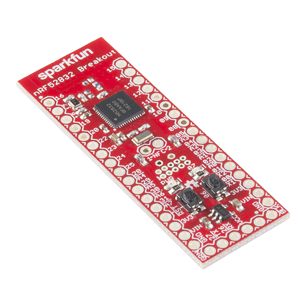
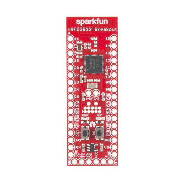
SparkFun’s nRF52832 Breakout provides easy access to all of the chip’s features. It breaks out all of the nRF52’s I/O pins, provides a 32.768kHz RTC crystal, a user-programmable button and LED, and a trace antenna to send and receive those 2.4GHz transmissions. Plus, to make the chip as easy-to-flash as possible, the breakout comes pre-programmed with a serial bootloader.
Nordic’s nRF52832 is an SoC that combines an ARM Cortex-M4F microprocessor with a 2.4GHz multiprotocol radio. In addition to providing access to all of the chip’s I/O pins, the breakout board includes a handful of external components. The nRF52832 can operate on a power supply between 1.7 and 3.6V. The board also includes a 3.3V regulator with a maximum input of 6V, if you want to power the board with batteries or a regulated wall supply.
- Bluetooth Low Energy (BLE), ANT and proprietary 2.4GHz radio support
- 32-bit ARM Cortex-M4F Processor
- Easy access to all 32 GPIO
- SPI, I2C, UART, PWM and ADC I/O support
- User-programmable LED and button
- 32.768kHz RTC Crystal
- Pre-programmed serial bootloader
- Arduino board definition available!
SparkFun nRF52832 Breakout Product Help and Resources
nRF52832 Breakout Board Hookup Guide
November 17, 2016
How to hookup and program (in Arduino!) the nRF52832 Breakout -- a development board for Nordic's BLE/ANT/2.4GHz system on chip.
MIDI BLE Tutorial
February 22, 2018
Developing a bidirectional MIDI-BLE link with the nRF52832 Breakout.
Looking for the nordic SDK guide?
Here is a link for Nordic's guide to using the nRF52832 with the Nordic SDK => http://infocenter.nordicsemi.com/index.jsp?topic=%2Fcom.nordic.infocenter.sdk5.v12.0.0%2Fnrf51_getting_started.html&cp=4_0_0_1 .
Bootloader Tips and Tricks
If you are having trouble getting the nRF52832 Breakout into bootloader try placing the board on a non-conductive surface (or plugged into something like a breadboard) and then either make sure your fingers are ONLY touching the buttons or use something like tweezers or even a M/M jumper wire to press the buttons. This results in much more consistent behavior getting this board into bootloader mode.
Window XP
This is not compatible with Windows XP.
Core Skill: Soldering
This skill defines how difficult the soldering is on a particular product. It might be a couple simple solder joints, or require special reflow tools.
Skill Level: Noob - Some basic soldering is required, but it is limited to a just a few pins, basic through-hole soldering, and couple (if any) polarized components. A basic soldering iron is all you should need.
See all skill levels
Core Skill: Programming
If a board needs code or communicates somehow, you're going to need to know how to program or interface with it. The programming skill is all about communication and code.
Skill Level: Competent - The toolchain for programming is a bit more complex and will examples may not be explicitly provided for you. You will be required to have a fundamental knowledge of programming and be required to provide your own code. You may need to modify existing libraries or code to work with your specific hardware. Sensor and hardware interfaces will be SPI or I2C.
See all skill levels
Core Skill: Electrical Prototyping
If it requires power, you need to know how much, what all the pins do, and how to hook it up. You may need to reference datasheets, schematics, and know the ins and outs of electronics.
Skill Level: Rookie - You may be required to know a bit more about the component, such as orientation, or how to hook it up, in addition to power requirements. You will need to understand polarized components.
See all skill levels
Comments
Looking for answers to technical questions?
We welcome your comments and suggestions below. However, if you are looking for solutions to technical questions please see our Technical Assistance page.
Customer Reviews
3.9 out of 5
Based on 9 ratings:
3 of 3 found this helpful:
great board
Great board. It works well and it is easy to program using SWD and the Nordic DK which I previously used for development. I suggest buying a breakout board like this before thinking your firmware is complete. It turns out aspects of my code that worked on Nordic's DK did not work with this breakout. I was therefore able to fix my program before starting the design of my own PCB. I've been working with nRF52 for my senior year project as an ECE and this product and additional files have been excellent resources.
5 of 5 found this helpful:
Great value; inexpensive powerful board with BLE
This is a good board, it does exactly what I need. It was almost trivial to get the Bluetooth up and running, and control a stepper motor controller through it (which also leverages SPI libraries). I've not tested I2C.
The SparkFun Arduino IDE plugin made it simple to get started and accomplished all of the above. My only complaint is that it doesn't include a straightforward flash access functionality from the nRF SDK out of the box. This would be handy for accessing flash without having to do a lot of research. I spent a few hours deep-diving into the SDK, which has half a dozen ways to access flash with various configurations that may or may not work depending on how the device is configured. The best option would be if they could add support for FDS, which is a record-based filesystem driver in the nRF SDK, but it has a fair amount of dependencies and requires understanding of the SoftDevice that might need to be abstracted away for the average Arduino user. nrf_nvmc on the other hand is pretty simple and standalone, and doesn't require any SoftDevice config. You just read internal flash directly from memory addresses and write to addresses in bytes or words using the library functions.
While they do provide their bootloader code, it would also be nice for noobs if they provided their procedure for installing the bootloader to a new chip. I buy from SparkFun for prototyping, but ultimately I want to make my own board. If I want it to work like this one, I do have the Nordic docs regarding bootloader installation, but I'm going to have to do some trial and error to figure out the options they used when flashing the bootloader package. UPDATE: I found their procedure in the Makefile located in the bootloader source repo: https://github.com/sparkfun/nRF52832_Breakout/blob/master/Firmware/bootloader-custom/sparkfun/dual_bank_serial_s132/armgcc/Makefile -- "make flash_softdevice".
ONE WORD OF CAUTION - This device by default is capable of being powered by the serial interface. Unfortunately, the power from this interface does not go through the VIN voltage regulator as one might hope. It goes directly to VDD, so be sure you use a 3.3v serial adapter. I literally caused the nRF chip to smoke and bubble a bit by using a serial adapter configured for an Arduino at 5V. Luckily (perhaps amazingly), nothing got damaged before I noticed my mistake.
2 of 2 found this helpful:
Okay but wrong schematic!
I like that the breakout board has the nrf52 on it with all the I/O broken out. Super helpful! It worked out good for the project I was on but it lacked a good 3.3V regulator. The 3.3V regulator Vin max was 6V. I really needed something that could work with Li batteries at around 7.2V. I had to put a different regulator on the board that I thought was pin for pin compatible but the Sparkfun schematic was incorrect for this part and needless to say caused irreparable issues to a board before I caught the difference. The board should really use the TPS76933DBVR regulator. Goes up to 10V!
1 of 1 found this helpful:
Really having fun with this. Works as expected.
It was super tough setting up for C after the bootloader just disappeared, but I wasn't much interested in BL. Not much help for using C with this part. I am using the Segger Studio (which is free for Nordic parts, yay!) and a J-Link EDU. I see there is a $20 Adafruit J-Link EDU. I am using the Nordic SDK but it is specific for Nordic dev boards, what a pain in the butt. Not only that, Segger has a SDK for this part auto installed as well. Have to be sure I am not mixing SDK's (like headers). I got it working though, but big learning curve. I plan to clone and extend the Arduino libraries in Git, so you can do stuff besides BLE and gpios.
2 of 2 found this helpful:
Challenging board to use ...
I was working on a project that was using the RedBearLab BLE Nano v2. When I finished the prototyping, I went to order the quantity I needed for deployment, but found that they were discontinued. (Ugh!) I looked to this board to replace the RedBearLab parts, but this board (while hosting the same Nordic chip) is much more difficult to use.
- Getting the board back into the boot loader is a challenge. The two button sequence seems to require very specific timing. It takes me a number of tries to get the board to jump into the program loading mode. (If you are having trouble, just keep trying, you will eventually get it.) It would have been nice to implement the reset following the Arduino model.
- The "hookup guide" only details how to get the BLEPeripheral library functional, but that does not help if you need to run the board as a "central" role. So, I can't directly port my application to this board without some serious extra work.
- As others have mentioned, the 3.3V regulator has a max input voltage of 6V. In my case, this makes powering the board a challenge, as the BLE Nano V2 could handle up to 13V on the VIN line.
I am hopeful that I can find a way to port my BLE central application to this board, but I was disappointed that the hookup guide ignores the "central" role that this board is capable of.
2 of 2 found this helpful:
Nice item but disappointed by minimal software library support for Arduino
I needed a Bluetooth LE device that was compatible with the Arduino GUI. Well based on my reading this was the best choice for low power and Arduino interface support.
However, my project is for a Bluetooth device in Central mode not in Peripheral/Server mode. Unfortunately I have not been able to find a suitable nRF52832 Arduino library for Central mode. AdaFruit nRF52 libraries appear to support Central mode but are only available for their devices. Unless there is a hidden Central mode library out there; this project is at a stand still.
So I am back where I started, uncertain how to accomplish my project in the Arduino GUI.
I look forward to putting the SparkFun nRF52832 to use in a different project... Some day.
????
Love it!
The nRF52832 is a very robust chip, and this breakout board makes it extremely easy to get started prototyping with it. It's got a nice set of features, and of course - excellent Sparkfun documentation!
Nice breakout board, but useless without external programmer
The serial boot loader does not really work. I could use it to program the chip once, but after that, the button press procedure no longer works. I biught the Nordic developlment kit as external programmer, but I would have preferred not to be mislead by the mentioning of an internal boot loader as it is not useful for repeated programming during development.
Hello!
Sorry to hear about the trouble with the nRF board's bootloader. Have you contacted our technical support department over at Techsupport@sparkfun.com - they may be able to help out with setting the board back into DFU and bootloader mode so that you can upload without an external programmer.
We bought this board to develop a Windows PC mouse application starting from the HID_test.ino example from the BLEPeripheral Library recommended in the Hookup Guide. Running the example as-is overwrites something in the bootloader or perhaps the Softdevice as the board will no longer boot into the application. We have isolated the offending function in the example to: bleHID.clearBondStoreData(); However, commenting this line out and attempting to pair with a Windows 10 PC results in a "Driver Error" from the PC. Further, there does not appear to be currently any support for the board or the BLEPeripheral Library.
Looks like you may be the same guy that opened the issue on GitHub, but just wanted to share the solution to the clearBondStoreData() problem here too.
https://github.com/sandeepmistry/arduino-BLEPeripheral/issues/164#issuecomment-311051910
You are correct and thank you again for your help but unfortunately we still get the Windows 10 "Driver Error" and still no support from SF or Github :( Nordic at least tried but it is not their code.
I got as far as the BLE Button example, when I started to have trouble. I thought "Maybe I need to power it from another source", and when I plugged it into my breadboard a rogue jumper wire shot 12v across one of the pins. POOF. there goes 20$. :(
Pro Tip. get the ftdi beefy, and don't leave old jumpers on your breadboard between projects.
Which pins are used for I2C/TWI by default?
I2C defaults to pins 20 and 21 for SDA and SCL, respectively. That default is set in the board variant - you should be able to adjust those constants to set it to just about any other pin.
Thanks for the tip! Tech support got I2C working with the nRF52832. Try looking the tip labeled " I2C with the nRF52832 " in my comment for more information and an example => [ https://learn.sparkfun.com/tutorials/nrf52832-breakout-board-hookup-guide/discuss#comment-58599a84f3b1a8770f8b4567 ].
Can anyone confirm that TWI/I2C works? PIN 21 is hardwired to the RESET button.
I changed the SDA and SCL pins in the board variant, but I still can't communicate with an I2C sensor. I've also tried disabling the pullups on SDA/SCL and set the pin drive modes to either S0D1 (Standard '0'. disconnect '1' ) or H0D1 (High drive '0', disconnect '1'), since I have external pullups on my SDA and SCL lines, but my sensor still won't talk back.
Just got back into the embedded/hardware world so I am without an oscilloscope and can't debug this properly, unfortunately.
For reference, the device I'm trying to communicate with is a SI7021 temp/humidity sensor with 10K pullups. Sensor communicates properly with an Arduino Mega 2560.
On a side note, the nrfutil executible loaded onto my machine was an ARM EABI5 binary; I'm running x86_64 linux. I ended up just installing nrfutil manually.
Okay, I can confirm TWI works :) In the end, after mucking around and digging through source code and pulling and plugging in wires, I had inadvertently switched up SCL and SDA. (Rookie mistake... this is what happens when you switch careers from embedded systems to cloud software).
Setting the pin drive mode to H0D1 (or S0D1) and disabling the internal pullups was the solution for my particular case.
Hi,
I am facing almost the same situation. I am trying to use an MPU6050 sensor over I2C on pins 13 and 14. How did you set pin drive mode to H0D1 via Arduino IDE?
Thanks!
1) How can I connect this with Arduino Lilypad USB Plus? Do I need an additional tool?
https://www.sparkfun.com/products/14631
2)How far it can detect a NFC tag?
Hi there, it sounds like you are looking for technical assistance. Please use the link in the banner above, to get started with posting a topic in our forums. Our technical support team will do their best to assist you.
That being said, I think you might have the wrong product. I don't remember this product being able to scan NFC tags.
Hi, Couple of questions.
Can the internal part of the MCU is powerful enough to drive no pixels?
And
Can the Arduino core be used to talk to other devices like this using the proprietary NRF protocol? Can it be used to talk to NRF2401 devices?
Hi there, it sounds like you are looking for technical assistance. Please use the link in the banner above, to get started with posting a topic in our forums. Our technical support team will do their best to assist you.
I've prototyped with the breakout board and now I spun a custom board. I am trying to upload the bootloader to it and am pretty lost.
I downloaded nrfutil on ubuntu. I have both a STlinkV2 and a serial adapter. It seems nrfutil is just meant to communicate over serial. I also tried using the Android nrfconnect app to do dfu but do not see the device. Will it broadcast as a blank chip? Do I need to do some fancy reset?
So in nrfutil in the command line I typed
The output was: not a zip file. Where do I get a zip file?
Thanks!
Okay I read that nrfutil has to make the zip file first. I have no idea if this is right because there are two hex files in the github but I tried:
and then the dfu command was happy with that zip but it is upset about my serial port.
I was developing a device on the Adafruit feather nRF52 but the voltage regulator is linear and two big for the application I'm developing. I was just wondering what the characteristics are of this board(Not the MCU). Can you implement energy saving API's on the arduino IDE with this board? What current does it draw in sleep if it is still connected to a device via BLE? Thanks.
What range have people been able to get with this board?
Help with PWM hookup. I bought this breakout board as well as the TB6612FNG motor driver board to hookup 2 dc motors. I cannot find any info at all on PWM pins on the nrf52832 board. I see a reference to PWM modules but I have no idea how to wire this up or what code is necessary beyond what I have done on the arduino. I am a newbie but hey, everybody starts somewhere right? Yes, I know I can use the arduino or whatever, but I want to use the nrf52832 to gain experience with it. thanks in advance....Ron
¿Can this be programmed with a custom GATT Service Profile for BLE?
Is this board FCC or CE certified?
Nope, check out our FCC tutorial on how our stuff fits in with FCC guidelines. The short answer is as prototyping hardware it is not required to be certified. While most boards like this are built using the manufacture's suggested circuit and should have no problems passing certification for a final product we do not go through the process to get our boards certified.
Thanks for the quick reply. By the way, I bought a few of these boards to do some prototyping for my research project. They're great! Thanks for the hardware.
Where would I get a 2x5 socket for the Cortex debug connector?
Anyone knows that if this breakout can be used to read the ADC and then transmit the data with BLE? If it is possible, can I just use Arduino IDE to write the code? Thanks, guys!
I want to hack my treadmill and emulate an ANT+ foot speed (foot pod) sensor to get better pace accuracy than my Garmin FR235 can deliver when used with a Garmin foot pod. Any clue where to start looking for other similar projects using this board? Other hints on how to get started? I have done tons of arduino and raspberry pi projects. Have extensive electronics experience and the treadmill already has a wheel with a magnet that I can use for a switch to provide input to the board.
Any way to hook up an external antenna?
This is very nice board. I really like it. Now I could use some help for my project. My goal is to send data from a sensor that stores data in a 16 bit unsigned integer. I was able to send that data through BLE UART using the seria.ino file in the examples as a reference. However, the only way I was able to do that was by sending the data after taking 16 bit values and splitting them into two separate 8-bit values and using the BLESerial.write function since the function can only send 8 bits (one byte) at a time. Is there another way of communicating that will allow me send more information at a time in a single instance.
Also, I see in the comments that the TWI and I2C lines on the board are pins 20 and 21 on the board. However, there is no pin 21 on the board for the SCL line. Do I have to change the definitions like how it is explained here in the tutorial: https://learn.sparkfun.com/tutorials/nrf52832-breakout-board-hookup-guide/discuss#comment-58599a84f3b1a8770f8b4567.
Thank you.
My board do not blink the blue LED to move to bootloader mode. pulling pin 6 down and pressing reset button do not respond at all. Both the red LED and blue LED glow all the time. looks like the default bootloader is corrupted. Any idea to recover to the default bootloader mode?
Is there any way to access the Schematic except from Eagle?
Yes, just click on the 'Schematic' link in the product description above.
The SPI interface does not appear to work. I attempted to communicate with the LSM9DS1 breakout, with no success.
I ended up finding the issue: pins 10 and 9 are, by default, reserved for NFC use and therefore cannot act like GPIO pins. One option is to disable them in the code, another is to just not use them. Switching the CS pin to a different GPIO fixed the problem.
https://devzone.nordicsemi.com/question/55696/struggling-with-basic-gpio-read-on-nrf52/
Does the Arduino Bootloader peacefully coexist with the Nordic 'softdevices' (ie, S212 & S332)? Is it replaceable/restoreable through the SWD interface?
The boards ship out with the S132 soft device installed, and the bootloader should be able to update that image if you need.
The bootloader on our board is a slightly modified version of Nordic's nRF5 v11.0.0 SDK HCI/UART bootloader (source can be found here). Using nrfutil v0.5.2, you should be able to package up and upload an application, SoftDevice, or even a new bootloader.
There's lots of good info on creating an image to bootload and running the bootloader over on Nordic's SDK reference page. Our Arduino hardware definitions can at least help get you started, though.