- Home
- Product Categories
- Distance
- TFMini - Micro LiDAR Module (Qwiic)

TFMini - Micro LiDAR Module (Qwiic)
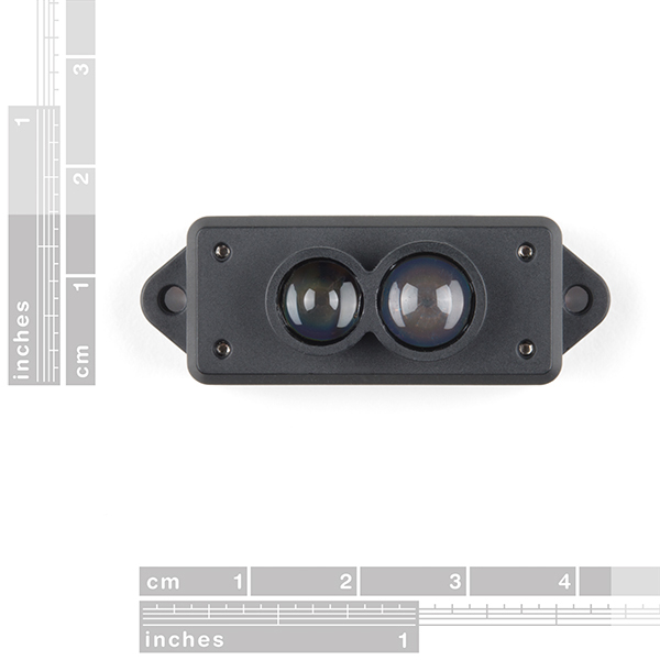
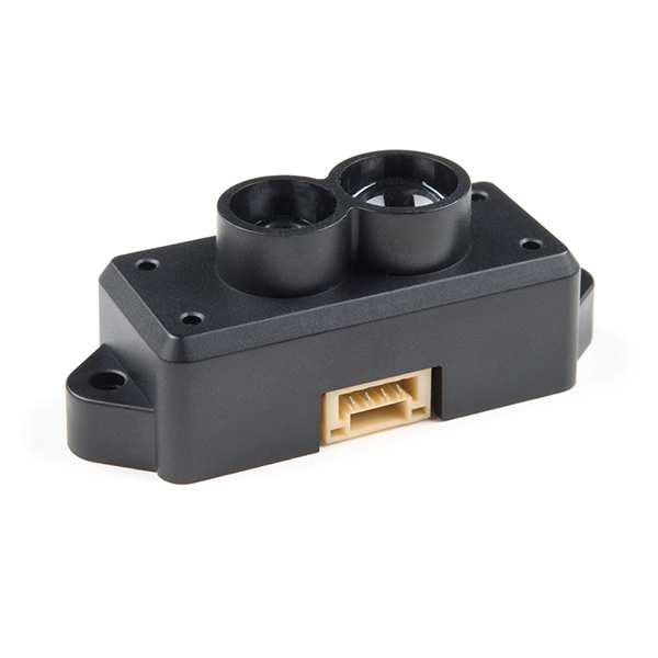
The TFMini is a ToF (Time of Flight) LiDAR sensor capable of measuring the distance to an object as close as 30 centimeters and as far as 12 meters! As with all LiDAR sensors, your effective detection distance will vary depending on lighting conditions and the reflectivity of your target object, but what makes this sensor special is its size. Measuring only 42x15x16mm, the TFMini allows you to integrate LiDAR into applications traditionally reserved for smaller sensors such as the SHARP GP-series infrared rangefinders. Because this sensor is now I2C connecting multiple sensors is now possible. Over 100 sensors can be connected but note that each sensor will require approximately 800mA so size your power supply accordingly.
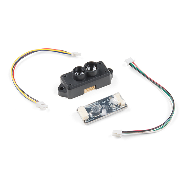
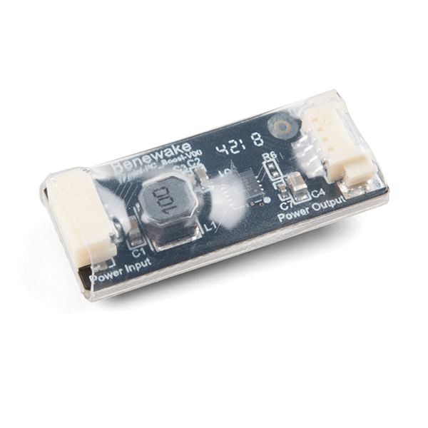
This version of the TFMini is even easier to use thanks to the addition of the included Boost Board making this micro LiDAR Module capable of connecting to SparkFun's Qwiic Connect system! The TFMini comes with a cable that connects the LiDAR module to the boost board and another that connects them to the Qwiic system. If you are looking to use a breadboard with your TFMini we recommend picking up a Qwiic Adapter to hook you up.
NOTE: The I2C address of the Micro LiDAR is 0x10 and is software configurable. A multiplexer/Mux is required to communicate to multiple Micro LiDAR sensors on a single bus. If you need to use more than one Micro LiDAR sensor consider using the Qwiic Mux Breakout.
Important: This product does not use laser light for ranging. Instead it contains an LED and optics. Many such systems are being marketed under the name "LiDAR," although it may be more appropriate to think of this device as a "Time-of-Flight Infrared Rangefinder". It differs significantly from traditional IR rangefinders in that it uses ToF to determine range and not triangulation — as is performed by the Sharp GP-series devices.
- 1x TFMini - Micro LiDAR Module
- 1x Boost Board
- 2x Hookup Wire
- Resolution: 1cm
- Maximum Reads Per Second: 100
- Minimum Detected Object Size at 2m: 20mm
- Operating Wavelength: 850nm
- Signal Acceptance Angle: 2.3°
- Default I2C Address: 0x10
TFMini - Micro LiDAR Module (Qwiic) Product Help and Resources
TFMini - Micro LiDAR Module (Qwiic) Hookup Guide
November 8, 2018
The TFMini is a ToF (Time of Flight) LiDAR sensor capable of measuring the distance to an object as close as 30 cm and as far as 12 meters! The TFMini allows you to easily integrate LiDAR into applications traditionally reserved for smaller sensors such as the SHARP GP-series infrared rangefinders. With the added Qwiic feature, you can quickly connect to the sensor via I2C!
Core Skill: Programming
If a board needs code or communicates somehow, you're going to need to know how to program or interface with it. The programming skill is all about communication and code.
Skill Level: Competent - The toolchain for programming is a bit more complex and will examples may not be explicitly provided for you. You will be required to have a fundamental knowledge of programming and be required to provide your own code. You may need to modify existing libraries or code to work with your specific hardware. Sensor and hardware interfaces will be SPI or I2C.
See all skill levels
Core Skill: Electrical Prototyping
If it requires power, you need to know how much, what all the pins do, and how to hook it up. You may need to reference datasheets, schematics, and know the ins and outs of electronics.
Skill Level: Competent - You will be required to reference a datasheet or schematic to know how to use a component. Your knowledge of a datasheet will only require basic features like power requirements, pinouts, or communications type. Also, you may need a power supply that?s greater than 12V or more than 1A worth of current.
See all skill levels
Comments
Looking for answers to technical questions?
We welcome your comments and suggestions below. However, if you are looking for solutions to technical questions please see our Technical Assistance page.
Customer Reviews
2.6 out of 5
Based on 5 ratings:
Goes into error state
While testing the LiDAR would go into an error condition (returns only 0xfffe, or 0xfffd) and not recover until after a power reset. I added code to send a reset to the LiDAR if an error was detected but that didn't work. I am still playing with it and there may be a solution I have not discovered yet. Also, in the sample code if byte 0 of the LiDAR data is zero then it is an error. I think this is wrong because the LiDAR is sending the data of its previous frame due to it being busy on the current frame. Due to the difference in frame rate and polling rate this will occur quite often but the data is valid unless distance data contains an error code.
Inconsistent readings
The readings are inconsistent, even sitting still, there is no data available 50% of the time even if just polling 2/sec. When this occurs it is returning previous data. The accuracy of the data is off consistently, for lidar I would expect better but is conststently off by several centimeters meaning this couldnt be used for piloting in large rooms.
Data valid: mode:3 strength: 1102 Distance: 170cm 66.9290in Data: 10AA09803 complete Data valid: mode:3 strength: 1102 Distance: 170cm 66.9290in Data: 00A909803 previous data Data: 004209323 previous data Data: 10420B023 complete Data valid: mode:3 strength: 10223 Distance: 66cm 25.9842in Data: 10420D223 complete Data valid: mode:3 strength: 10342 Distance: 66cm 25.9842in Data: 101E09500 complete Data valid: mode:0 strength: 1044 Distance: 30cm 11.8110in Data: 001F09500 previous data Data: 001F09500 previous data Data: 001F09200 previous data Data: 10AA09803 complete Data valid: mode:3 strength: 1102 Distance: 170cm 66.9290in Data: 10A909803 complete Data valid: mode:3 strength: 1102 Distance: 169cm 66.5353in
It is a good devise for its cost.
Still can not find out how to change an I2C address of this sensor in case if I want to connect more then one sensor on the same I2C bus with Arduino. If anybody can help, I will really appreciate that. Thank You!
Caveat emptor
I purchased two and was unable to get data from either. I tried Pi 3 B, Arduino Uno, 101 with external power. It would appear the uart version is much more reliable
Challenging Sensor!
This sensor was /is very challenging. My goal with this sensor was to use it outside either on a power wheels or measuring 39-40' distances on my property. I immediately attached an SSD1306 .96 OLED which caused much consternation. Originally, I tried both on a QWIIC MUX board and soon gave that up. I then attached the TFMINI (boost) to direct QWIIC and the OLED to a Grove shield which failed. I then attached the OLED directly to the QWIIC RedBoard (also tried the QWIIC BLackBoard c) which finally provided readings.
The next step was portable. I tried various power sources including a LI battery rated at 2A. I even tried attaching a 9V to the barrel connector (per recommendation).
Limited success with a bulkly portable unit.
As with other comments, spurious results and screen blanking (assume it perceived the distance was more that than the 3v3 could handle).
I rate the sensor as OKay because it does work in a limited fashion and I learned much from experimenting.
Instead of the "boost board" I would like to see an option for 5V operation (another board which provides/allows 5V power and 3v3 volts for the signal lines). Only then can I determine this sensors potential. I am not real saavy yet with how to make the signals 3v3 volts or I would do it myself.
I am also testing lighted environments as I thought the readins went haywire in a bright environment - still testing.
Still can not find out how to change an I2C address of this sensor in case if I want to connect more then one sensor on the same I2C bus with Arduino. I did an address scan and see that all of the sensors initially have same address 0x10. In their manual it is written that address is "configurable" between 0x10 and 0x78. But no words about how to do that change. If anybody can help, I will really appreciate that. Thank You!
Glancing through the documentation, I don't see a refresh rate listed anywhere. Anyone with sharper eyes than I can spot this, or have experience?
It looks like that this TFMini is capable of outputting up to 100 readings per second.
Yes! This. I would recommend that ~all~ sensor parts listed for sale have sample rates defined or explained. This type of information is pretty much always needed. I'm trying to think of an example of when I don't care what the sample rate of a sensor is and I'm drawing a blank.