- Home
- Product Categories
- LoRa
- SparkX SAMD21 Pro RF 1W


SparkX SAMD21 Pro RF 1W
This product was retired with the introduction of the new and improved Version 2 SAMD21 ProRF 1W. The new version can be powered with up to 15V out-of-the-box, is designed for a cleaner RF signature, and puts the flash memory on a separate SPI port in order to be compatible with Micro/CircuitPython. The silkscreen labels on the new version are a lot prettier, too!
LoRa stands for 'Long-Range,' referring to a modulation technique whose specialty is low power transmission of small data packets -- perfect for Internet of Things applications. Using either point-to-point radio or LoRaWAN you can send data from a node in a remote location back to your base station to check in on sensors or track equipment. Communication is possible in the other direction as well to send commands or control actuators!
Like the LoRa®-enabled SparkX Pro RF this board is based on the Semtech SX1276 transceiver, but the module boasts a whopping 1W output power. All that extra oomph makes it possible to send small messages up to 9 miles using common rubber-duck type antennas.
In addition to more transmission power the SparkX SAMD21 ProRF 1W gets more computational power courtesy of the SAMD21 microcontroller running at 48 MHz. We used the additional GPIO pins to permanently enable LoRaWAN signals. This means more pins for you to connect to sensors and actuators, even when connecting to a LoRaWAN network like The Things Network.
Checkout the SAMD21 Mini/Dev Breakout Hookup Guide as a general starting point for the SAMD21 Pro RF 1W.
To get you started we've included some basic P2P examples.
Experimental Product: SparkX products are rapidly produced to bring you the most cutting edge technology as it becomes available. These products are tested but come with no guarantees. Live technical support is not available for SparkX products. Head on over to our forum for support or to ask a question.
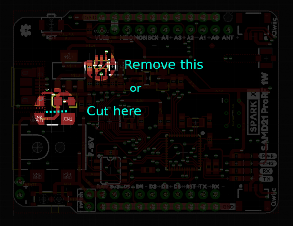
Battery Input Voltage The silkscreen label near the barrel jack states an input voltage range of 7-15V. Although this is correct for the regulator voltages over 7V will damage the battery charging IC. We recommend powering the board with a 5V source through the USB cable. If you must use a high voltage battery (over 7 V) please remove the charger IC or cut the VBATT trace as shown in this image.
- Semtech SX1276 transceiver with 1W amplifier
- U.FL and PTH wire antenna connections
- Atmel SAMD21 microcontroller with Arduino bootloader
- 4MB flash on SPI lines
- 15 IO pins:
- 1x SPI
- 1x UART
- 5x analog
- 5x digital
- Qwiic enabled with 2 ports
- Onboard 5V and 3.3V regulators
- Barrel jack connector or PTH for battery input (up to 15V with white-wire fix)
- Battery power on/off switch
- USB connection for programming and serial output
- Example Sketches used for range testing
- Datasheet for the E19 module
- Datasheet for the SX1276
- Schematic
- Eagle Files
- Hookup Guide:
- To get the latest files please visit the GitHub repo
Comments
Looking for answers to technical questions?
We welcome your comments and suggestions below. However, if you are looking for solutions to technical questions please see our Technical Assistance page.
Customer Reviews
No reviews yet.
opps ignore the last item question -- directions where clearly given for SAMD21 set up :)
A few questions
Is that a mico or mini USB?
the "Battery Input Voltage" Disclaimer says to power around 5v.. Would a 3 AA pack (4.5v) be enough or best to use a 4 AA pack (6v)?
In the example product code it has "#define LORA_DEFAULT_SPI_FREQUENCY 500000 " This is on the 915 mhz ? is the 500000 number just a random number and need replaced ?
<edit: question added>: It appears there is a u.FL connector on the side with the USB connector and one on the actual chip mounted on the back-- What u.FL connector would have the best "RF energy output" ?
Would you follow these instructions for setting up with Arduino (for board selection / when uploading the sketch ) https://learn.sparkfun.com/tutorials/samd21-minidev-breakout-hookup-guide/setting-up-arduino
Hi, I hope I can help answer some of your questions! 1. It is a micro USB connector 2. The best bet would be to use 4 AA batteries for 6V input. The reason is that the E19 RF module is designed to operate at 5V and the linear regulator onboard has about 1V dropout. 3. You can increase that number (500 kHz) to something more typical of SPI communication such as 1 MHz or possibly even 5 or 10 MHz. Just keep in mind that testing was done at 500 kHz so I am not sure what the upper limit is. 4. Yes, the u.FL connector on the E19 module should have the best RF output, but it will require you to either move that 0402 0-ohm resistor to the other position or try to close the gap with solder.
As a final note: stock of this item is running out. For the re-stock we have made some changes to address the problems with the very first release. The most significant changes are:
I expect that these new models will be in stock some time next week.
Thanks for the detailed response
One last question that I think would be of general interest, it appears this module and the RFM95 (part number SPX-14785) and this module both are based on SX1276 LoRa®
Can they communicate with each other? SPX-14785 is based off of the "RadioHead" library --- I have tried a few times and can't get the r SPX-14785 to receive packets from the parkX SAMD21 Pro RF 1W *even at close distances
You are correct, they are both based on the SX1276. I have sent packets between the two ( SparkX Pro RF and the SparkX SAMD21 Pro RF 1W ) however I did not use the RadioHead library. Rather I used the same arduino-LoRa library on both devices. The catch is that the pin definitions are different between the two so you'll need to modify the code. The easiest way is to include LoRa.h directly in each sketch folder and change the #defined default pins. Here's the schematic for the 32U4 ProRF so you can figure out which pins to define :D
If you need to use the RadioHead library it still should be possible, I just haven't tested it. I say that because the LoRa modulation is standardized so once you have radio waves going out anything listening for LoRa should be able to get it.
Good luck and keep us posted!
Did you address the RFM95 using arduino Lora with
LoRa.setPins(10, 9, 2); <-- changed to the appropriate pins for the sparkfun board. Also, are they in the order of CS RST INT ?
I never used "LoRa.setPins()" because I just redefined the default pins, however I looked in the library and you are correct about the order.
I have a hunch that you need to call "LoRa.begin()" after "LoRa.setPins()" also.
FYI for the first version of this board (x01 in bottom copper layer) the pins should be: - Chip Select (SS): 12 - Reset: 13 - INT: 6
(Those pin numbers may change a little for version x02)
Ahhhhh!!!! AWESOME! THANKS!!!