- Home
- Product Categories
- WiFi
- SparkFun WiFi IR Blaster (ESP8266)

SparkFun WiFi IR Blaster (ESP8266)
Do you want to control your TV via a web-browser? Want to ask Alexa to mute your stereo? Want to schedule triggers to your IR-controlled LED strip? These are all applications that the WiFi IR Blaster is perfect for. The SparkFun WiFi IR Blaster is designed to connect all of those old, legacy IR-controlled devices to a WiFi network exposing them to a new method of control with the Internet of Things.
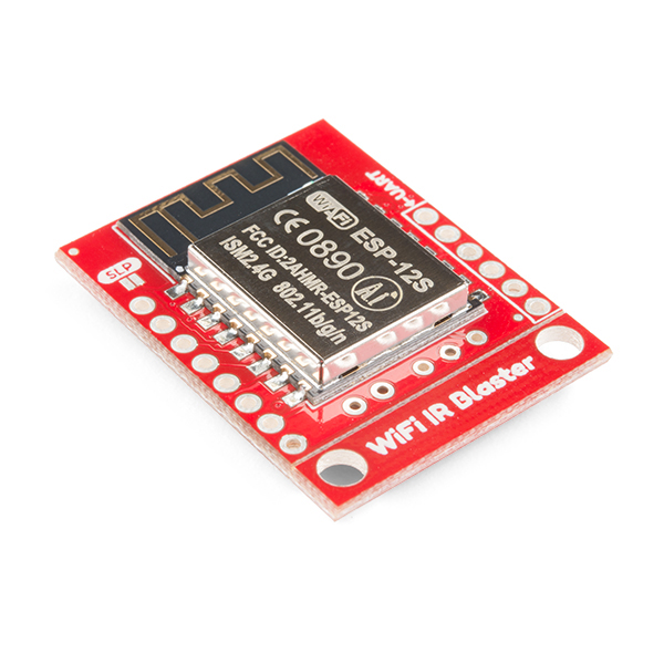
The WiFi IR Blaster combines an ESP8266 – a powerful WiFi/microcontroller SoC – with IR emitters and receivers. With built-in WiFi support, the ESP8266 can be programmed to provide an interface between HTTP, MQTT, TCP, and infrared-controlled devices. This module equips the ESP8266 with a crystal, 4MB flash, and a PCB antenna – just about everything it needs to get going. Please be aware that the antenna sits under the SparkFun logo on the board, so try not to place anything that may interfere with WiFi signals near that area.
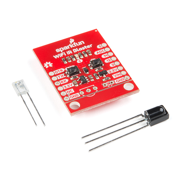
The IR emitter and detector components are packaged with the board, but not soldered in place. This allows you to solder both components at any angle your project requires. It also leaves the option to customize the board and spec out your own emitter and/or receiver. So some soldering will be required to get the WiFi IR Blaster operational.
- 1x SparkFun WiFi IR Blaster
- 1x LTE-302 IR Emitter
- 1x TSOP382 IR Detector
SparkFun WiFi IR Blaster (ESP8266) Product Help and Resources
Using Home Assistant to Expand Your Home Automations
May 9, 2019
An introduction to Home Assistant, an open source home automation hub.
SparkFun WiFi IR Blaster Hookup Guide
December 6, 2018
How to assemble the WiFi IR Blaster and program it using Arduino. You'll be controlling IR devices from the web in no time!
Core Skill: Soldering
This skill defines how difficult the soldering is on a particular product. It might be a couple simple solder joints, or require special reflow tools.
Skill Level: Noob - Some basic soldering is required, but it is limited to a just a few pins, basic through-hole soldering, and couple (if any) polarized components. A basic soldering iron is all you should need.
See all skill levels
Core Skill: Programming
If a board needs code or communicates somehow, you're going to need to know how to program or interface with it. The programming skill is all about communication and code.
Skill Level: Rookie - You will need a better fundamental understand of what code is, and how it works. You will be using beginner-level software and development tools like Arduino. You will be dealing directly with code, but numerous examples and libraries are available. Sensors or shields will communicate with serial or TTL.
See all skill levels
Core Skill: Electrical Prototyping
If it requires power, you need to know how much, what all the pins do, and how to hook it up. You may need to reference datasheets, schematics, and know the ins and outs of electronics.
Skill Level: Rookie - You may be required to know a bit more about the component, such as orientation, or how to hook it up, in addition to power requirements. You will need to understand polarized components.
See all skill levels
Comments
Looking for answers to technical questions?
We welcome your comments and suggestions below. However, if you are looking for solutions to technical questions please see our Technical Assistance page.
Customer Reviews
4.8 out of 5
Based on 5 ratings:
1 of 1 found this helpful:
Fits my needs...
Although this device works very well it does not come with any IR firmware preloaded. That's not a bad thing, just letting others know.
The placement of the emitter and the sensor are easy, just follow the instructions. I recommend that you use a "fine tip" soldering iron.
The mounting holes are a nice touch and useful to me (somewhat). But I would have preferred that they were permanent and at the other end of the board.
Be patient with the firmware you choose to load onto it. The source I used has various adjustments that needed tweaking to get my remote to be received reliably. Once you've got that this device becomes convenient for decoding remotes and creating a program that transmits commands.
1 of 1 found this helpful:
Home Assistant and ESPHOME Compatible
I've been using this for automating my stereo system and tv with home assistant and ESP-home, using the sparkfunBlynk template. Its uptime is good and is powered via my tv's usb port (not all tv usb ports work similar).You will have to do some work in figuring out the multitudes of ways engineers encode their data, it won't always be easy, but many use NEC, and you'll always have raw data to record, which this device allows. The ADC pin can also be used as a raw button pin via ESPhome.
You can salvage better IR leds from old tv remotes, or buy 5mm clear leds to fit your needs. I just shoved this in a too small hammond box and covered the whole thing in LEDs. With the amount of modding I've attemped on this bad boy I have damaged the thin traces to the IR output but I just have a bigger resistor from 3V3.
My only con is that ESPhome gets higher in bytes every patch, so wireless updating with many ir codes will have you fighting to keep save every bit, but if you program by header it will program no problem. I guess you could store a database of helper entities in home assistant, and the only code on the device for outputting the proper data, but I haven't gotten around to it, and so far haven't hit the true limit.
works great and proves what can be done
Works Pretty Well
I was able to solder the diodes easily and put a 6 pin header into place to allow me to program the ESP8266 from the Arduino IDE on my Mac. First I tried an old Sparkfun FTDI basic breakout but couldn't get the driver to work so I used a CP2102 USB to TTL adapter that used a different driver. The only annoyance was that it didn't have the DTR pin, so I had to press the buttons on the IR Blaster board each time I wanted to send a program.
First I ran the receiver program so I could point my remote control at the receiver diode and then get the codes for each button on the remote as I pushed it. Then I pasted the codes into the web server sketch and tweaked it to allow me to communicate with the server via WiFi and then have the IR Blaster send these codes to the TV and cable box. I rewrote portions of the code to make this all work in the manner I preferred.
One initial roadblock is that the simple NEC Codes didn't seem to work on my TV or cable box, and I later discovered that my cable box didn't use the NEC protocol anyway, but rather something called GICable. Thus I ended up using the longer raw codes as described in the Sparkfun Hookup Guide and had to rewrite some portions of the Arduino sketch as a result. Maybe I could look at the documentation for the IR Blaster Arduino library a little more to see if I could send simpler codes, but the example code only showed NEC format and raw format.
Once everything was working, I wrote a simple app for my iPhone that allowed me to have logos for the various cable stations that I could push and send the corresponding request to the web server (which would then send the IR raw code via the WiFi blaster) as well as pretty buttons for the volume and channel controls and the on/off buttons for the TV and cable box. Now I only have to use one control (the iPhone) to control both devices.
Of course for a few more $$ I could have bought a fully-assembled and enclosed IR blaster from any number of suppliers, but I would have been tied to their own control software. All told it took me about a day or two of coding and experimenting to make everything work the way I wanted it to.
After following the hookup guide, this device streams out seemingly random numbers when I put it in listen mode, even with the device in the dark. This happens no matter which firmware I use.
Copying and pasting the numbers after an attempt to record a remote command, the IR LED is outputting something, but it definitely isn't the same thing that my remote is putting out.
Help?
I have to say, it took a bit of time to get this working, but I finally was able to. Some issues I had: when using the Beefy3 FTDI board, I was only able to see serial output using the Arduino serial monitor. In order to use other terminal programs, I had to connect a UART to VCC, GND, RX, TX and then I could get serial out. Also, I found the LED builtin pin was #2. Very fun!
Can anyone tell me what is the transistor used and the voltage regulator, because on the schematic files they are hidden ?
Hi there, it sounds like you are looking for technical assistance. Please use the link in the banner above, to get started with posting a topic in our forums. Our technical support team will do their best to assist you.
I don't have part numbers (not at work), but that looks like a 3.3V regulator (we normally use one that is rated for 500-600mA) and the other part looks like NPN MOSFET.
Yeah, well I burned out the transistor and the regulator and I want to replace them can you tell the components data sheet or name ?
Could not for the life of me get this device to work with Arduino IDE's serial monitor. It is as if it doesn't have the correct bootloader pre-programmed to work with any of the examples in the tutorials. I cant get the device to get past the boot-loader's startup message at 74880 Baud. It's supposed to change to 115200 Baud after this startup message and then output the data collected on the IR (according to the tutorial). I couldn't even get it to compile and output serial data at all with the most basic program. I was hopeful, but looks like I've wasted a day going nowhere. Very disappointing.
I had a similar issue. I found that connecting an FTDI directly to the GND, VCC, TX, RX pins and then I was able to get serial IO.
Someone removed the video. The link no longer works.
If you are referring to the link in the newsletter we caught an error a little too late and had to remove it. The video is up to date on this page in the image carousel or you go directly to the video here.
Do you intend to propose the same product witjh an ESP32 instead of the old ESP8266 ?