- Home
- Product Categories
- Infrared
- Infrared Emitters and Detectors

Infrared Emitters and Detectors
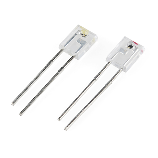
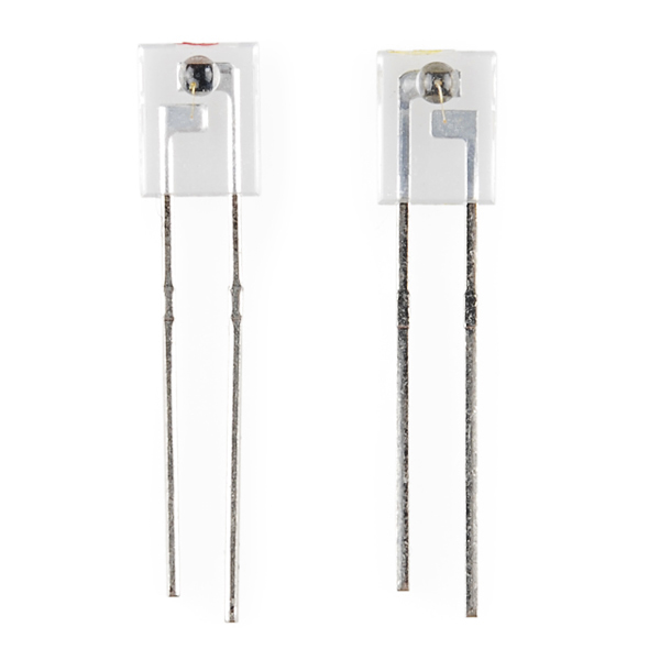
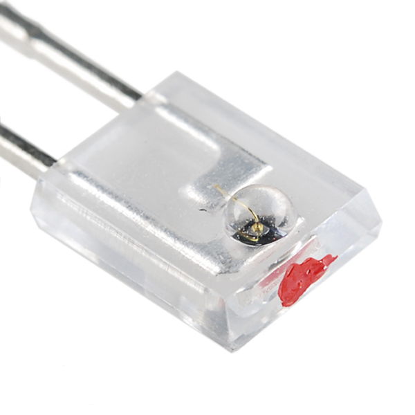
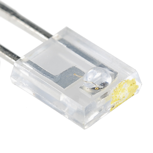
Side-looking Infrared Emitters and IR Detectors. These simple devices operate at 940nm and work well for generic IR systems including remote control and touch-less object sensing. Using a simple ADC on any microcontroller will allow variable readings to be collected from the detector. The emitter is driven up to 50mA with a current limiting resistor as with any LED device. The detect is a NPN transistor that is biased by incoming IR light.
Datasheets:
- IR Emitter (Yellow dot)
- IR Detector (Red dot)
Applications:
- IR Schematic - Basic object detection schematic
Robot Room - Excellent website with lots of goodies
Sold as a pair, with one Emitter and one Detector.
Infrared Emitters and Detectors Product Help and Resources
IR Communication
February 7, 2013
This tutorial explains how common infrared (IR) communication works, as well as shows you how to set up a simple IR transmitter and receiver with an Arduino.
Simon Tilts Assembly Guide
December 3, 2013
This tutorial will guide you through assembling your Simon Tilts PTH Kit.
SparkFun WiFi IR Blaster Hookup Guide
December 6, 2018
How to assemble the WiFi IR Blaster and program it using Arduino. You'll be controlling IR devices from the web in no time!
IR Control Kit Hookup Guide
October 2, 2013
How to get the most out of the infrared receivers and transmitters included in the IR Control Kit.
Core Skill: Electrical Prototyping
If it requires power, you need to know how much, what all the pins do, and how to hook it up. You may need to reference datasheets, schematics, and know the ins and outs of electronics.
Skill Level: Rookie - You may be required to know a bit more about the component, such as orientation, or how to hook it up, in addition to power requirements. You will need to understand polarized components.
See all skill levels
Comments
Looking for answers to technical questions?
We welcome your comments and suggestions below. However, if you are looking for solutions to technical questions please see our Technical Assistance page.
Customer Reviews
4.8 out of 5
Based on 6 ratings:
1 of 1 found this helpful:
replacement parts for Irobot roomba
exactly what I needed
1 of 1 found this helpful:
Fixed Roomba!
Purchased these to fix one of the bumper switches on my Roomba vacuum cleaner. Worked like a charm. Cheapest fix I've ever done.
1 of 1 found this helpful:
Works great
Sensors are great. Works really well.
WARNING: DO NOT FEED ANY MORE THAN 5 VOLTS!
I made that mistake, and feed the emitter more than five volts. It flashed really bright, pooped and died.
2 of 2 found this helpful:
Exactly what our Roomba 510 needed
After years of faithful service, our 510 Roomba started doing the boogie fever circle dance, for which the only prescription is more cow. . . Uh, I mean new emitters and detectors for the bumper sensor. We took it apart, switched out the old with the new, put it back together, and crossed our fingers when we pressed the start button. It worked perfectly! (Until the battery died, but that's another problem for another store.)
1 of 1 found this helpful:
Excellent!
Made a bunch of beam block detectors using ATTINY85s to modulate the beam and ignore ambient light. Very easy to use.
1 of 2 found this helpful:
Eccellent
Very quick shipping and packaging, parts worked with no problems
Does anyone know if i can use this to make a simple hard wired circuit to turn on a motor from about 12 feet? If not, will using an arduino connected to the detector and the motor work? I would appreciate a quick reply as the project is time sensitive.
which resistors do i need to incorporate these components into a 5V circuit ?
In case anyone is curious, here's what the response on the detector looks like. Channel 1 (the higher line) is the detector, and the other line (channel 2) is the emitter. Each horizontal line marks 1 volt and each vertical line marks 50 microseconds. So, it takes the detector about 250 microseconds to get from about 5 volts to 0 once the emitter is turned off.
Thank's, that is useful. It also shows that the detector reacts practically in an instant.
The shipment I just received had the detectors marked with a red dot and the emitters marked with a yellow dot. This should probably be noted somewhere.
When the detector is setup with a voltage divider (10k resistor and 5V), it reads about 2.0V. When I block a fairly large light coming from the next room with my hand, it drops to about 1.75 volts. So ambient light is an issue.
Anyone know which "bin" these parts come from? The datasheets list pretty different values for radiant intensity and on current for the emitter and detector depending on the bin.
Note that the emitter and detector are directional in regards to the small bulb or lens that is on one side of each. I couldn't figure out why the emitter had such a minimal effect on the readings from the detector until I pointed both of the bulbs at each other. The range is actually quite good even with all of the ambient IR from lights in the room. Even at distance of about 6 inches, blocking the emitter makes a significant difference in the detector reading. Hope this information helps.
JerrA's code is a good place to start, but has any used 2 sets of these to monitor a doorway. I went to know when someone enters or leaves a room.
I ordered this pair and received 2 emitters and no detector. Who do I contact about this?
Could I take the set of these, and turning them both 90 degrees away from the other(so the emitter and the detector are pointed in the same direction instead of at each other) could I get a reading from reflections of nearby objects, like say a hand? I'd like to use it as a motion sensor, like what you'd see on an automated soap dispenser.
I come from the future to say, "yes". Really, that is how most IR proximity sensors work (ever take an old VCR apart?).
Why would there be an IR proximity sensor in a VCR? I've taken several apart and don't remember seeing any.
And have you actually tried it? If so, do they work well with a retroreflector, for break-beam detection (like a garage door safety sensor)?
I think I've only seen like one or two total. I've not actually tried it, but it shouldn't be that hard (as a proximity sensor). Just set up the detector to drop voltage and use an ADC to test the voltages. You might even be able to get the voltage to fluctuate enough to use a digital input. As for beam breaking, you can at smaller distances with no filtering (two or three inches).
With this pair I was able to successfully decode the power button signal from a Comcast remote control, and create a program that will switch the power of the cable box on and off at pretty much any interval of time that I want (limited by the Arduino). The final setup consists of the emitter and the Comcast receiver box, and it works from across the room.
Datasheet links appear broken. Links take me to a blank page. Can anyone help?
I'm able to see a noticeable difference in XMega ADC readings (12 bit) across dark/light color differences from a flat surface about one inch away. I think there's even some room for improvement with oversampling.
Though not as handy as the QRD/QRE sensors, the IR transmitter's max forward current is 50mA, twice that of the QRE1113. That extra power translates into extra range. You'll need to test for your own requirements if these will work though - standard YMMV disclaimer applies.
what sort of range for detection do we stand to get with this package?
Has anyone used these for making Infrared Pulse Sensor? They seem more practical then using the larger LEDs in most projects.
They should work, the frequency is in the right region. You'll need to construct something that ensures that the light is bounced through the skin rather than directly from the emitter to the detector.
Could I use these in this application?
http://www.miscjunk.org/mj/pg_pdt.html
What I'm worried about is having 3 of the lined up about 3 inches apart, and pointing at each other over a distance of about 5 to 8 inches. Will they have a tight enough focus not to interfere with each other? Or is this where I should be using different "carrier frequencies" as mentioned in the video accompanying this?
Note: I'm a total beginner with electronics so I'm not really up on all the lingo.
I would only turn one on at a time. In other words: turn on emitter 1, read sensor 1, turn off emitter 1; turn on emitter 2, read sensor 2, turn off emitter 2; turn on emitter 3, read sensor 3, turn off emitter 3; repeat at high frequency.
Does anybody know if the detector can demodulate 38khz or not?....been looking all around but nothing really came up and i have no clue if it will be able to i know the tsop####etc. can do it but i want to know this particular set since i have a couple
These things are very effective at capturing remote control outputs. I've create a program that does that here: https://github.com/atomicpunk/arduino/blob/master/infrared/infrared.ino. The range is only about 5 feet using the IR schematic shown, but it's enough for testing purposes. A circuit with an amplifier and filter should give several more feet.
Could you post an example of an amplifier and filter for these? I'm very interested to increase the range on these. Thanks!
Does anybody know if these guys will communicate with the black IR emitters and receivers such as ones you could find ona a TV remote and on the TV itself?
Looks like it.
Would the IR Schematic under "Applications:" for this product require a very consistent power supply or would just using a cheap little 5v regulator be good enough? Would I have to use something like the circuit in Sparkfun's first embedded electronics tutorial? JoelQ
Total noob question here.
I'm trying to integrate an infrared detector into an Irdroid infrared blaster ( http://www.irdroid.com/ ) and wire it in through the mic loop, which has around 2.2V put through it. I could also wire it in with the Irdroid's battery (6V) and use a transistor to open/close the mic loop.
Would something like this work in a situation like the one stated above?
EDIT: Whoops! didn't realize it needed 5V. I guess the latter option would be the only one that's viable.
any idea when these may become available?
Just tried this, can get around 2 inches of semi-reliable detection =(
I just received these yesterday and used them to repair the front bumper sensor on my Roomba 500 (560) series robot. I used the link below, thanks so much!
TEST AND REPAIR PROCEDURES: http://www.schneordesign.com/Avi/irobot/roomba_mod2.htm
Regarding Sparkfun: QUALITY PARTS — FAST SHIPPING — RECOMENDED SUPPLIER.
Can these two be used for Universal remote? If not then whats the use of them?
Note that the white LEDs I used are extremely bright(I can't stare into them) and pointed directly at the detector about an inch away. I haven't encountered problems with common household ambient light, except for direct sunlight.
A bit of an update. It appears that the detector is at least a bit sensitive to ambient light that isn't infrared. Shining white LEDs at it causes a very noticeable change in reading. But, I've found a way around it. A regular piece of exposed 35mm film in front of the detector. I put 2 layers of 35mm film in front and for a distance of only about an inch from the emitter, the detector will yield values of 0.02 when the emitter is off, and 0.7 when the emitter is on. With a set of super bright white LEDs shining at the detector, then the values will be 0.3 with the emitter off, and 0.9 with the emitter on.
So if you are having problems with a lot of ambient light staring straight at the emitter, you might try just putting a few layers of 35mm film in front of it. In my case, without the 35mm film with the white LEDs pointed at the detector, I got readings of 0.94 with the emitter off and 0.95 with the emitter on.. so this little trick could definitely save a project if you're having this kind of problem
Fixed my Roomba's bump sensors with these guys! See http://www.schneordesign.com/Avi/irobot/roomba_mod2.htm. Works great!
To all the people complaining ambient light messes with the detector's reading. This is not possible to prevent. Take a camera that sees infrared and a piece of 35mm fully exposed camera film. Put the film over the camera lense and you'll see almost nothing but infrared.
The main ambient light sources that put out a bunch of infrared for me, are the incandescent light bulbs in my house. I get readings of about 0.8 when my desk light is on compared to 0.1 when it's off. LCD screens do not appear to give off hardly any infrared. I would bet that fluorescent lights don't give off any infrared either. Sunlight of course, is an infrared spot light. There is nothing sparkfun(or physics) can do to make the perfect detector that only sees your little emitter. The only thing you can do is use coding to differentiate your emitter from all the noise.
Also, I've confirmed that for the most part, this is only sensitive to infrared light. If you stick a non-infrared LED pointing at the detector, the readings don't change.
Also, one last thing: I found http://www.societyofrobots.com/schematics_photoresistor.shtml to be a much better tutorial for using photoresistors(ie, the detector) than the linked web pages.
Well bugger. The emitter and detector look exactly the same to me...I don't see any of this "tinted pink" thing.
There's always the trick of looking at it with a digital camera. IR light shows up on a digital camera.
I would imagine that this trick would work best with a more inexpensive camera (a camera on a cell phone, for example), as SLR's generally have an IR filter (some stronger than others).
I was able to test a TiVo remote using my grandpa's iSight, and other webcams probably work too.
I had the same issue. If you have a multimeter with a diode test mode, use that. You should only be able to get a reading when oriented correctly on the detector (the phototransistor). The positive probe goes on the collector (longer lead). Worked great for me. Make sure you're not in too dim of a room when you do this.
Just by way of avoiding confusion, it might be cool if items sold as a pair didn't picture a pair of pairs.
i wanted to know, if someone has used this sensors, whether these sensors are sensitive to ambient light???????????
waiting for reply..
Judging from the rest of the comments, ambient light might be a bit of an issue. I'd suggest putting a directional shroud or something around them in order to make it more directional...
How far is the range on these? Could you sense something across the room?
What are the odds I can point the detector at a peice of white letter size paper, then point a 940nm laser diode at the paper from a distance and trigger the detector?
I wrote about using these to test a camera shutter at the Arduino forum here:
http://www.arduino.cc/cgi-bin/yabb2/YaBB.pl?num=1233960430/
These couldn't have been easier to use.
Where are the plain photoresistors?
In case you somehow haven't found them after six years of searching, here you go.