- Home
- Product Categories
- Development Tools
- 40 Pin AVR Development Board

40 Pin AVR Development Board
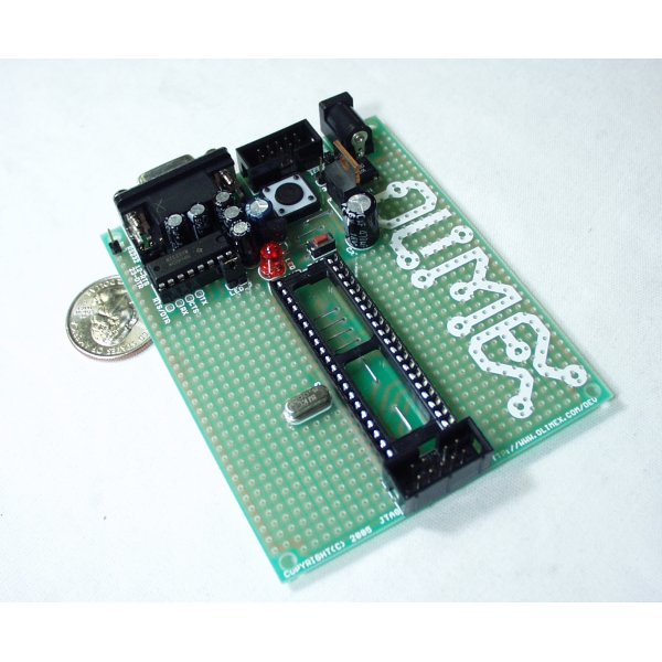
Prototype board for 40 pin Atmel ATMega microcontrollers with power supply circuit, 8MHz crystal oscillator circuit, RS232 port, reset IC, status LED, and 10 pin STK ICSP port.
Notes: Board does not come with AVR Microcontroller installed. Please see a list of related items below.
- STK200 compatible ICSP 5x2 pin connector for in-circuit programming with AVR-PG1 or AVR-PG2
- JTAG 5x2 pin connectr for in-circuit programming and debugging with AVR-JTAG-USB and AVR-JTAG-L
- RS232 Tx, Rx interface with MAX232 IC on socket
- 8 MHz crystal on socket (user can replace with any value)
- reset IC ZM33064
- reset button
- general purpose push button
- status LED connected to PB0 via removable jumper
- DIL40 microcontroller socket
- Power plug-in jack
- selectable +3.3V / +5V power supply voltage regulator
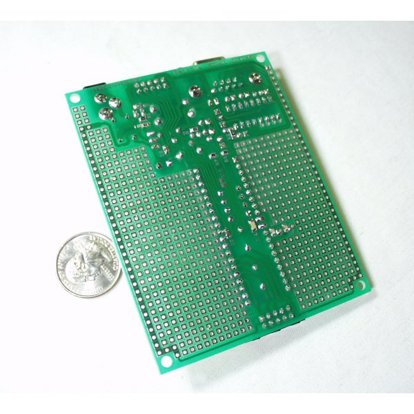
- extension pin headers for each uC pin
- four mounting holes 3.3 mm (0.13")
- GND bus
- Vcc bus
- FR-4, 1.5 mm (0,062"), green soldermask, white silkscreen component print
- 100x80 mm (3.9x3.15")
40 Pin AVR Development Board Product Help and Resources
Core Skill: Programming
If a board needs code or communicates somehow, you're going to need to know how to program or interface with it. The programming skill is all about communication and code.
Skill Level: Competent - The toolchain for programming is a bit more complex and will examples may not be explicitly provided for you. You will be required to have a fundamental knowledge of programming and be required to provide your own code. You may need to modify existing libraries or code to work with your specific hardware. Sensor and hardware interfaces will be SPI or I2C.
See all skill levels
Core Skill: Electrical Prototyping
If it requires power, you need to know how much, what all the pins do, and how to hook it up. You may need to reference datasheets, schematics, and know the ins and outs of electronics.
Skill Level: Noob - You don't need to reference a datasheet, but you will need to know basic power requirements.
See all skill levels
Comments
Looking for answers to technical questions?
We welcome your comments and suggestions below. However, if you are looking for solutions to technical questions please see our Technical Assistance page.
Customer Reviews
No reviews yet.
In case anyone wants to know: this board is working perfectly for me with an ATMega1284P chip (which is like a souped-up ATMega32: 128K of program memory, 16K RAM, extra timers, 2 UARTs, etc.).
You don't need to remove the ZM33064 Brown-Out Detector for 3.3V operation, if it's easier, you can remove the 0-ohm SMD resistor connected to it. See the schematic. I'm using it with AVR Studio 4.x and a 10-pin cable to real STK500, though the STK500 USB dongle works too.
Hey matt, i thought the atmega32 needs 5v ? i didnt know we could use 3.3v? I'll be using this in conjunction with a bluetooth module. and all this time I thought I would need to step down the voltage?
The atmega32 needs 4.5-5.5v to run. Although the atmega32L is the same chip but it can run 2.7-5.5 but speed is limited to only 8MHz.
If you don't the extra speed the atmega32L is good but for speed, a logic level converter would need to implemented with the atmega32.
hi guys, can anyone confirm if this will work with AVRStudio? and what cable would u guys recommend for pc connection
If you plan to use this dev board with the 3.3V supply, be sure to remove the Brown-Out Detector IC (it's the transistor-looking IC between the red LED and the two buttons (reset button and big round button).
If you don't do this and use the board with 3.3V, your microcontroller will be held in reset and nothing will work.
I just wasted several days banging my head against the wall trying to figure out what I was doing wrong. Removing the brown-out detector IC fixed everything.
I hope this helps you out.
-Matt