- Home
- Product Categories
- Development Tools
- 8 Pin AVR Development Board

8 Pin AVR Development Board
Replacement: None. We are no longer carrying this dev board but check out the rest of the AVR development tools! This page is for reference only.
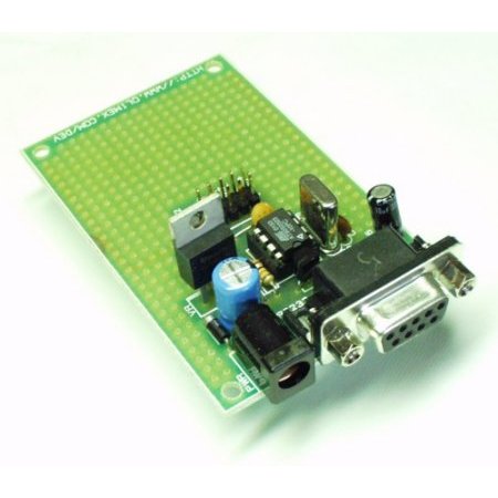
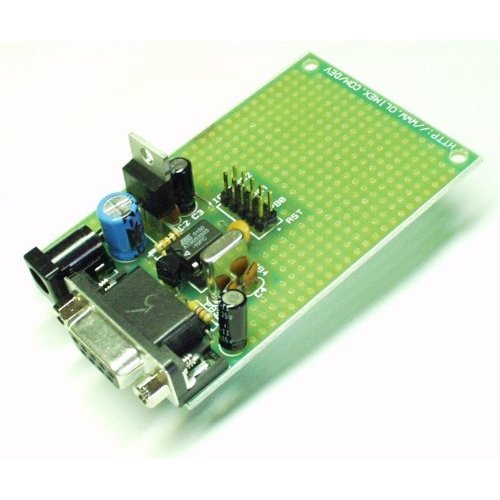
An excellent entry level prototype board for 8 pin AVR microcontrollers with power supply circuit, crystal oscillator circuit, RS232 port, and STK 10 pin ICSP port.
- FR-4, 1.5 mm (0.062"), green solder mask, white silkscreen component print
- ICSP 5x2 pin connector for in-circuit programming with AVR Programmers
- Voltage regulator +5V, 78L05 and filtering capacitors
- Quartz crystal oscillator circuit 10MHz available - Must use internal 9.6MHz osc on ATTiny13
- DIL8 microcontroller socket
- RS232 DB9 female connector
- RS232 interface circuit
- Extension slot on every uC pin
- 4 pcs mounting holes 3.3 mm (0.13")
- Grid 100 mils
- GND bus
- Vcc bus
Board does not come with AVR Microcontroller installed. Please see a list of related items below.
- 58x81 mm (1.7x3.2")
Comments
Looking for answers to technical questions?
We welcome your comments and suggestions below. However, if you are looking for solutions to technical questions please see our Technical Assistance page.
Customer Reviews
No reviews yet.
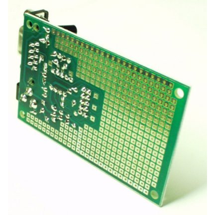
Nice little development board for 8 pin AVR chips. The 10Mhz oscillator is not connected. If you want to use it you have to bridge two pads on the bottom. But for chips with internal oscillators just leave it as is. I might pull it off and use it in a different project.
The board has a +5V bus and 0V bus along the card edges. Each pin on the chip is available on a pad, but you might have to search for PB3 and PB4.
I plug the ICSP into my Arduino, pulling the +5V and ground using the edge busses, and find I can run SPI to the 8 pin chip.
This is a good board to get started with 8 pin AVR. Be sure to get a few Tiny13 chips when you order. Some extra headers for the board will also come in handy.
So is this thing a programmer? Product description is confusing. If not, does anyone have a programmer circuit I can use, preferrably with only discreet components? (I know it might not be possible. But always worth it to ask! By the way, I do NOT want to use an arduino to program it.)
This is not a programmer, it's a development board, which basically means a microprocessor with some useful hardware wrapped around it. You'll still need something to get code onto the chip.
There are numerous pages out there with DIY AVR programming circuits. You might also try our Pocket Programmer which is relatively inexpensive.
edit never mind, this is a dev board, not a programmer - face palm
Newb question... I have a small handful of ATtiny13's that I'd like to play with; I've never programmed an AVR before (except for BasicX-24's a few years ago, different environment.)
If I download WinAVR and get this board (I have a serial cable already) is that all I need to program these chips?
FWIW, I already have a breadboard & the components for the project I have in mind.
These are nice little boards. I gave away my only one to a friend and assume it's now sitting in a box, in a cupboard somewhere (pearls spring to mind about now :-).
Anyway, I'm now searching for a low voltage/current 8-pin AVR board but after an initial search haven't yet found one.
What I mean is a board that make the most of say an ATtiny85's
low power usage by having a battery supply and low power reg (maybe switchmode).
Any idea folks?
The ATTiny85 doesn't really need any external components. It accepts a wide range of input voltages and can run at up to 16Mhz on its own internal oscillators. Solder one to a bit of perf board, connect some batteries and you're done. If you need low power you can reduce the clock frequency (default is 1MHz) and turn off unwanted parts of the chip. See the datasheet.
If I connect this to my PC directly, using the RS232 port, do you know how do I make the avrdude recognise this board? Or do I have to use a separate programmer?
It is programmed over ICSP.
I made an short instructable about using this board. Hope this is useful.
<font>Blinky LED using an attiny13, a USBTiny programmer, and olimex board - More DIY How To Projects</font>
I'm sorry if this is a really stupid question but I'm not sure I understand this development kit. If 2 pins are VCC and GND, 4 are used for MOSI MISO SCK and RST for the programming, and 2 are used for the crystal how do you interface with the uC? There are no pins left for I/O. I must be misunderstanding something here.
If you have stuff connected to the pins it will interfere with programming exactly as you say. The best answer is to develop your software/circuit on either the 14 pin version of the chip or an Arduino. Use the 8-pin chip for the final product. Anything else is a pain. This board is a bad way to do it IMHO.
If the circuit connected to MOSI/MISO/SCK will draw more than a few hundred uA when the programmer asserts them, or if you don't want those I/Os to be asserted for some other reason, then you'll need to add jumpers or some other means to let you disconnect your circuit from the microcontroller during programming.