- Home
- Product Categories
- Development Tools
- 20 Pin AVR Development Terminal

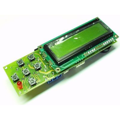
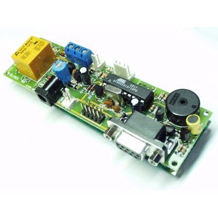
20 Pin AVR Development Terminal
Replacement: None. There is no direct replacement for this board. We have retired it and will no longer carry it. This page is for reference only.
A fun package full of potential projects! Development board for 20 pin AVR microcontrollers with power supply circuit, crystal oscillator circuit, reset IC, RS232 port, STK ICSP port, 16x2 alphanumeric LCD display, 6 button keyboard, Dallas touch button port, frequency input, relay with 5A/250VAC contacts, buzzer, status LED.
Supported Devices: AT90S1200, AT90S2313, ATtiny2313
Board does not come with AVR installed. Please see a list of related items below.
- FR-4, 1.5 mm (0.062"), green solder mask, white silkscreen component print
- Four mounting holes 3.3 mm (0.13")
- Dallas touch button port
- Frequency input
- RS232 DB9 female connector
- RS232 TTL levels output connector
- ICSP 5x2 pin connector for in-circuit programming with AVR-PG1B or AVR-PG2B
- Voltage regulator +5V, 78L05 and filtering capacitors
- Quartz crystal oscillator circuit 10MHz
- Reset IC ZM33064
- DIL20 microcontroller socket
- Relay with 5A/250VAC contacts with screw terminals
- Status LED for the relay
- Buzzer
- DC Power jack
- 120x36 mm (4.7x1.4")
- Datasheet
- Schematic
- AVR ICSP connector
- avr-mt.asm - Demo software (Thanks to Dr. Raphael Holzer)
Comments
Looking for answers to technical questions?
We welcome your comments and suggestions below. However, if you are looking for solutions to technical questions please see our Technical Assistance page.
Customer Reviews
No reviews yet.
I think you guys should make something like this, only all surface mount, FTDI chip, atmega328, etc. I'm not saying another arduino clone, but a dev board for a bare AVR with all the goodies like this one, but more.
Yeah, finally broke this guy out to play with it. Could not talk to it with an STK500 through the ICSP port, tried multiple chips, thinking I had a bad chip in it, that was not the case. I troubleshooted it down to the reset circuitry. First of all, the schematic says a 10k pullup to vcc, that was a 1k on my board, we usually use a 6.8k pullup, so 1k seemed a little small. I think that in combination with the reset supervisor would not allow the STK500 to pulse the reset pin the way it does for entering programming mode. I checked and it was trying, I would get a 0 pulse, not sure of the length (didn't scope it). After removing the reset supervisor and replacing the 1k with the 10k, it started working fine.
Hmm, last post didn't show up, must have hit cancel. Anyways, I could not get the buttons to work, even using that code. Either they would stay high or it would miss a button press. I think if you need to write zeros to the pin, give it time to get down, then turn it to an input, otherwise it will be pulled high instead of tri-stated. And I think you need to give some time after setting a pin to an output and making it high before you can read the full voltage on the output, that's why I was missing presses. Here is the code that I used with delays in it
void ReadButtons(){
PORTB = 0;
DDRB = (DDRB &= 0x0F);
DDRB.5 = 1;
PORTB.5 = 1;
delay_us(250);
if (PINB.6)
up_button = 1;
else
up_button = 0;
if (PINB.7)
ll_button = 1;
else
ll_button = 0;
PORTB = 0;
DDRB = (DDRB &= 0x0F);
PORTB = 0;
DDRB = (DDRB &= 0x0F);
DDRB.6 = 1;
PORTB.6 = 1;
delay_us(250);
if (PINB.5)
right_button = 1;
else
right_button = 0;
if (PINB.7)
center_button = 1;
else
center_button = 0;
PORTB = 0;
DDRB = (DDRB &= 0x0F);
PORTB = 0;
DDRB = (DDRB &= 0x0F);
DDRB.7 = 1;
PORTB.7 = 1;
delay_us(250);
if (PINB.5)
left_button = 1;
else
left_button = 0;
if (PINB.6)
down_button = 1;
else
down_button = 0;
PORTB = 0;
DDRB = (DDRB &= 0x0F);
}
And here is a video of it in action
http://www.youtube.com/watch?v=CnEgn1nWUlw
Also, you can put a ATTiny4313 on it, same pinout, just a larger capacity.
I have already purchased AVR terminal, attiny 2313 and DB9 connector. Did I buy all the required components? I have zero exprerience, so how do I start programming? Could anyone tell me? Thanks.
I suggest you try some of the tutorials in the Tutorials section. There will be some differences, since they use the AtMega168... But it should give you some tips on how to set up a development environment.
possibly a useless comment since this is going into the discontinued list, but don't forget that pins 15 and 16 on the lcd control the backlight. they aren't attached, but two of the L-header pins make it easy to attach to one of the 'spare' header pins.
I just received mine a few days ago and it is a fun little board to play with. LCD was easy to get up and running, I am using it with a Maxbotix LV-MaxSonar-EZ0 via usart. I think I will buy another one before they are sold out. Good price.
I Agree with Ben, maybe a joystick instead of buttons.
and a nother relay and.....and ....and....
I just got this thing a few days ago and so far I'm loving it. There are a few things I'm still kind of unclear on, so I wanted to see if anyone else has any ideas.
If I want to do IO (other than built-in buttons, light, and lcd) do I have to solder into the buttons or hijack one of the freq or ibutton inputs?
Similarly for interrupts, it looks like the ibutton goes to an interrupt pin, do you just hijack that and use it as an interrupt?
I'm working on a project where I'd like to be able to read a pwm signal from a maxbotix sonar rangefinder and output a pwm signal to a motor. It seems like I'll have to do some hijacking though... (too bad there weren't more pins broken out for general use).
Anyways, any ideas/suggestions are greatly appreciated.
Yeah, I'd be all over this thing if had a breakout for the available pins.
I bought this about 2 weeks ago. Today I finished writing an lcd driver in C.
When I bought this I had ZERO embedded hardware experience. I would reccomend this board to newbies, it has the advantage of being premade with the most common components, and the processor is easy to code for.
This board has even fell on my shag carpet from a few feet up (by accident) with no ill effects.
Also, that assembly code is EXTREMELY useful. Thank you Dr. Holzer ;)