- Home
- Product Categories
- Monochrome
- Serial Enabled 20x4 LCD - Black on Green 5V

Serial Enabled 20x4 LCD - Black on Green 5V
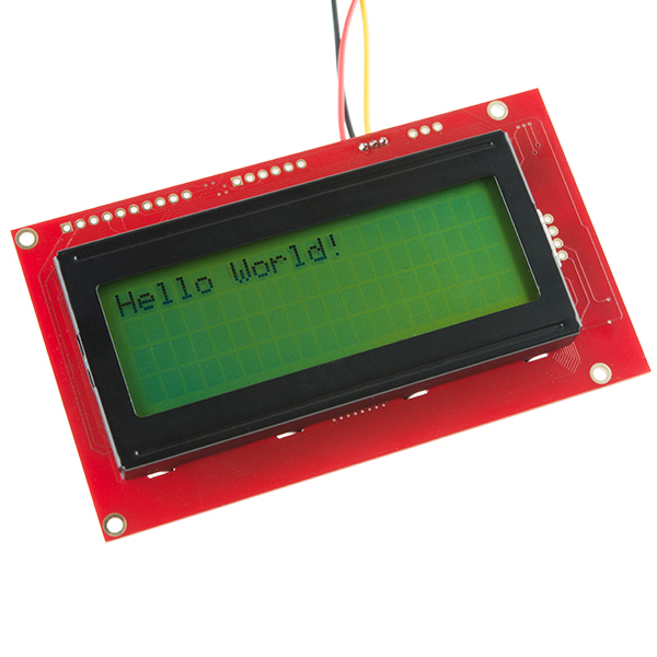
This is the latest evolution of our serial LCD. Included on a single board is a 20x4 LCD and an embedded circuit based around a PIC 16F88. The on-board PIC takes a TTL serial input and prints the characters it receives onto the LCD. The installed firmware also allows for a number of special commands so you can clear the screen, adjust the backlight brightness, turn the display on/off, and more.
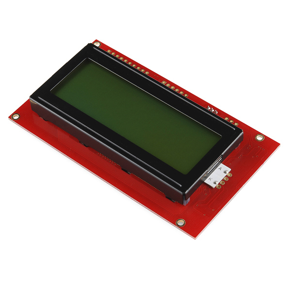
Communication with SerLCD requires 5V TTL serial at a default baud rate of 9600bps (8-N-1). You can adjust the baud to any standard rate between 2400 and 38400bps. The power (VDD), ground (GND) and RX pins are all broken out to both a 0.1" pitch header as well as a 3-pin JST connector.
SerLCD has the ability to dim the backlight to conserve power if needed. There is also a potentiometer on the back of the display to adjust the contrast.
- Embedded PIC 16F88 utilizes onboard UART for greater communication accuracy
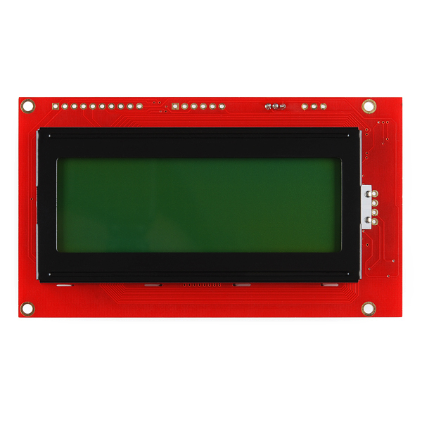
- 20x4 Black on Green LCD
- Adjustable baud rates of 2400, 4800, 9600 (default), 14400, 19200 and 38400
- Operational Backspace
- Greater processing speed at 10MHz
- Incoming buffer stores up to 80 characters
- Backlight transistor can handle up to 1A
- Pulse width modulation of backlight allows direct control of backlight brightness and current consumption
- All surface mount design allows a backpack that is half the size of the original
- Faster boot-up time
- Boot-up display can be turned on/off via firmware
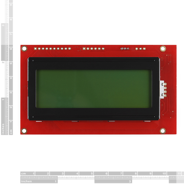
- User definable splash screen* PCB: 105 x 59.9 mm
- LCD: 87.3 x 41.8 mm
Serial Enabled 20x4 LCD - Black on Green 5V Product Help and Resources
PIC-Based Serial Enabled Character LCD Hookup Guide
May 29, 2018
The PIC-based serial enabled character LCD backpack is a simple and cost effective solution for interfacing to character Liquid Crystal Displays (LCDs) based on the HD44780 controller. The backpack simplifies the number of wires needed and allows your project to display all kinds of text and numbers.
Core Skill: DIY
Whether it's for assembling a kit, hacking an enclosure, or creating your own parts; the DIY skill is all about knowing how to use tools and the techniques associated with them.
Skill Level: Noob - Basic assembly is required. You may need to provide your own basic tools like a screwdriver, hammer or scissors. Power tools or custom parts are not required. Instructions will be included and easy to follow. Sewing may be required, but only with included patterns.
See all skill levels
Core Skill: Programming
If a board needs code or communicates somehow, you're going to need to know how to program or interface with it. The programming skill is all about communication and code.
Skill Level: Rookie - You will need a better fundamental understand of what code is, and how it works. You will be using beginner-level software and development tools like Arduino. You will be dealing directly with code, but numerous examples and libraries are available. Sensors or shields will communicate with serial or TTL.
See all skill levels
Core Skill: Electrical Prototyping
If it requires power, you need to know how much, what all the pins do, and how to hook it up. You may need to reference datasheets, schematics, and know the ins and outs of electronics.
Skill Level: Competent - You will be required to reference a datasheet or schematic to know how to use a component. Your knowledge of a datasheet will only require basic features like power requirements, pinouts, or communications type. Also, you may need a power supply that?s greater than 12V or more than 1A worth of current.
See all skill levels
Comments
Looking for answers to technical questions?
We welcome your comments and suggestions below. However, if you are looking for solutions to technical questions please see our Technical Assistance page.
Customer Reviews
3.5 out of 5
Based on 19 ratings:
4 of 4 found this helpful:
Easy to use - Easy to break
This is one of the those products that works as expected right out of the box. It was really easy to hook up a 9600 baud UART to it and start printing characters.
Unfortunately its just as easy to break. Because it has no I/O lockout on boot, it saves all settings on EEPROM between boots and because it is controlled using embedded control characters rather than either a dedicated control line, it will often read garbage characters during connection/disconnection and power cycles as control sequences and do everything from disabling the backlighting to changing baud rate. And there is no way (no obvious documented way that I can tell) to factory-reset it EXCEPT by using the UART interface, which is dodgy at best. Good luck ever recovering this thing once it reaches the tell-tale solid black 1st and 3rd lines.
This is an issue with which we are familiar. One of our techs wrote up the quick fix in the comments of the Quick Start Guide. Have a look here, it should help!
1 of 1 found this helpful:
Not good for development.
Agree with others who say it is too fragile to be practical. When it works, it is like any other serial 4X20 display; although, all but one command requires two writes. Fortunately, that one command is 0x12, which you will learn to use to unbrick it.
When using it to develop code, the slightest error will give garbage. More often than not, correcting that error or commenting it out doesn't get you back to a known state. It stays garbage until you rebuild/unbrick it from scratch. It is sad that that "bricking" has been a known problem for more than 10 years and has not been fixed.
I bought the SF display because it will operate at 38400 baud, and it will do that. But keeping code ready to fix it when it goes off the rails is an inconvenience at best, and of course, that code is not left in-line. As one of the other reviewers said, you have to bring it into the shop, fix it, then return it.
My plan for the SparkFun 20x4 serial LCD is to keep it and write new code for it, if I get time. Unfortunately, SparkFun cannot provide a schematic for it, so you are left guessing about some pins. There is a schematic of a backpack version on the web. While that version is generally accurate so far as the number of active components, simple probing with a multimeter will show that connections between the 16F88, LCD, and transistor on this display are different.
The display also injects a pretty substantial pulse at about 83 Hz into your power line. Perhaps that is from the backlight supply. Be sure to use ample decoupling.
Edit: 06/03/18 Developed new software that seems robust. That seemed to be the main problem. Also changed to a PIC16F1827 as I was more familiar with that chip, and it had additional capabilities. The 16F1827 and 16F88 are pin compatible. Changed to a 16 MHz crystal for a better selection of faster baud rates. Here is a link to the finished project with code: https://forum.allaboutcircuits.com/threads/fixing-the-sparkfun-4x20-lcd-display.148893/ One could keep the original crystal and simply change the baud settings and delays to accommodate it.
1 of 1 found this helpful:
Works Great!
I have owned one of these displays for about 5 months now I haven't had any problems since I completed writing my own object to control this display. I had several problems with my own code initially that resulted in dark first and third lines or random characters like the other reviewers but I was always able to reset my serial connection speed to 9600 baud using the instructions provided with it. Now that all of my control functions are working properly it has been displaying exactly what it is supposed to
1 of 1 found this helpful:
Works as expected.
It works as I expected it to. There are wires on the one pictured, probably so "Hello World!" could be displayed, but mine did not come with wires so I had to solder some on.
1 of 1 found this helpful:
One of these bricked itself while, even running on Software Serial!
This is really serious for me. The display was being used in a system that a user was travelling with. It has been working fine for weeks, but it seems that there is still a chance for these things to pick up garbage and freak out, even if it is not on the hardware serial lines. This failure was embarrassing, I will need to figure out a work-around, hopefully less of a kludge than only powering it up after the micro. Even doing that isn't satisfying, because a fix for a relatively rare failure is hard to verify. I'd appreciate any suggestions!
Edit: I am going to call tech support in a few minutes but, for me, the issue is not whether I can recover this particular board. What I must do is put in place some kind of robust fix/hack to prevent this from happening again in the field. I can deal with SMT soldering, so if there's a tested PCB fix in the works, I can likely implement it with a rework until it becomes available. Also, I don't think it's correct to suggest that Software Serial somehow was the cause of the LCD getting bricked.
Edit 2: I spoke with tech support, and they could neither give me any suggestions for work-arounds or re-works nor did they have a date for a replacement board. I'm experimenting with holding VPP low until the Arduino is booted and software serial is up and running.
Edit 3: It seems that the PIC is configured with VPP (MCLR) disabled, so controlling during power-up isn't as easy as I hoped. That still leaves the problem of handling power-down crud.
Just to be clear, this mostly works fine, but it is IMHO too fragile for applications where you really want it to keep working. In the situation I have, power is supplied from a regulated wall wart. When that is plugged into the Arduino board there are some messy transients flying around, (and also when it is unplugged). If I simply plug and unplug a bunch of times I can pretty reliably get it somewhat scrambled (splash screen messed up). If I get more abusive with deliberately bad insertions of the plug I can very easily get it scrambled. Obviously, I can spend time tweaking and adding electronics to handle these situations and so improve the situation, but I think it will never be robust enough to be worth the effort. Sadly, I am going to consider them a loss of time and money and am planning to replace them with another display module. If anyone has suggestions for a fix, I'm still all ears, but I can't spend more time on this...
Hello!
Sorry to hear about the trouble with software serial bricking the LCD. Have you contacted our technical support department at Techsupport@sparkfun.com - they're the best people to contact to get help with issues like these.
1 of 1 found this helpful:
One thing missing
This product is ALMOST the greatest thing ever...Almost.
For me, this is not simply a serial display, this is a ready made breakout board for the PIC16F88.... BUT NO.
If only the designer had broken out the UNUSED TX Pin.... WHY WHY WHY WHY was this pin left "NC" (as per the diagram)...its already there, you have broken out every other pin.... SF Engineer: "lets not break out the TX pin to mess with them".... I swear there must be a conspiracy behind this. So: 4 stars...
Other than that, this board works just fine, and was exactly what I needed. I wrote a brief serial "driver" to control it because I did not like the user interface with the special characters, commands and cursor positioning and other things. http://www.ccsinfo.com/forum/viewtopic.php?t=55546
....that TX Pin though.
3 of 5 found this helpful:
worst product!
I've bought about a over a dozen of these. All but three have gone bad. Symptoms are an all black screen or black lines across the first and third lines.
Hi there, So sorry to hear that you are running into this issue. It is common that if you leave these units connected to the UART, the programming of the control processor will scramble the LCD processor code. This is recoverable, however, this is not a defect of the unit. The best way to avoid causing this issue is to use a software serial setup to move your LCD communication lines to a different set of IO pins other than the hardware UART lines. If you find that you have put your screen into this state contact our tech support team and they can help you with directions on how to recover the module.
1 of 2 found this helpful:
Serial input failure
I agree with the previous reviewer on the quality of these. I've only run them from Arduino's and after awhile the serial input program seems to fail. It now turns on and shows the Sparkfun splash screen but any serial input shows vertical lines. If I unplug the screen and hook up another Sparkfun serial screen it shows the proper info. While it worked I really enjoyed the serial function.
Easy Breezy Serial LCD
I found this display straight forward and easy to work with. And no additional libraries to bloat your code. After a little study of the info available thru Sparkfun, the darn thing worked as intended the very first time. Spend a little time with the spec sheet, you'll be way ahead. Nice display.
Good product
Very simple to use with only 3 cables
Bricked
I thought I was going to be immune from the bricking issue already described (1st and 3rd lines all blocks) by using Serial2 on the Mega.
After months of reliable operation using the basic clear screen, move cursor, etc. commands, I thought I would reprogram the splash screen.
That's when the problems began and I bricked the display. I attempted the recovery procedure, but since I was not getting the default splash screen I knew there was a little chance of successful recovery.
If I were to do it again, I would probably get the standalone backpack board so that it can be trashed if bricked, while keeping the LCD.
Suggestion... Change the firmware and expose some header pins or a switch so that recovery can happen under almost any conditions.
Two out three ain't bad
I bought three of these displays. I got two of them to work. One of the displays would only give me gibberish on the display. I tried using different baud rates thinking that the default was changed. I tried resetting the baud rate. Nothing really worked. So I am sending that one back. The other two though work great.
In the Arduino documentation for connecting to the display, they allude that you can use their SEN-08733 JST 3 pin connector with the LCD. You can as a matter of fact, but you need to pay attention to the wiring. Normally +5vdc is red and power supply return is black while yellow is your serial communication line. This is how the 16x2 serial LCD displays are set up. Well, pins one and three are swapped on this display. So you can either swap the wires around on the connector or use red as your communication wire and yellow as your +5vdc wire. You just need to pay attention to how you hook it up.
Also, the "SparkFun SerLCD v2.5 Application Note" does not have clarity on the cursor position addresses. It just indicates that the addresses are 0x80+n. That is sort of true but the addressing is not contiguous as one might assume. Therefore you need to pay attention to the "SerLCD v2.5" datasheet which indicates the "viewable" cursor position for a 20x4 display in it (page 3).
Other than that, these guys are fun to program and play with. I set the baud rate to 38.4kb so I avoid program slow downs when displaying data and messages. It works very much the same as the 16x2 serial display (with exception to the wiring of the power and signal lines and the extra addresses for more cursor positions).
It is very simple to program once your used to generally programming character based LCD's. They are lots of fun.
Mr.
Hi, Thank you for your inquiry. We are on the point of installing the LCD displays and, therefore, cannot give you any feedback yet. Do you sell the same LCD displays 20 x 4 LCD black on white 5 volts? Please send me the part number. Best regards Juergen
Hi Juergen, I'm afraid we don't currently offer a 20x4, black on white, 5V LCD Display.
Works Great!
Pretty simple to operate. Great tutorial to go with it.
To easy to get in an unknown state
Been working on a project and the night before I needed it, something happened and it went into an unknown state. All it does is display two lines with black boxes. All attempts at unbricking it failed. I was left with either ordering a new one or buying a pic programmer to reflash it. I only chose to order a new one because I'm in such a rush to get this project completed and I don't want another learning curve at flashing it.
Hello!
We've heard that a lot. We're working on a new layout for one that does not have the same issues, but as a general rule of thumb you should always be careful about what you have directly connected to hardware serial lines while uploading to the Arduino. Have you contacted our technical support department at techsupport@sparkfun.com for help with the LCD in an unknown state?
Nice little display!
Easy to hook up and reasonable quality and price. Would like more support in terms of programming language to perform various tasks. I'm a Picaxe fan and there is no help specific to Picaxe. But I was able to fumble around and figure it out.
Would like to see someone like myself write up a support document which uses "English" to explain various programming terms. Just a thought.
Works well
This unit makes it easy to add a basic display to my projects. I like the ease of using the serial interface as it makes connection to a controller very simple.
Works great and intuitive
The board works as expected and the hardware interface is easy to accomplish. The software is intuitive.
Hello everybody! Does anybody know if there is an library of Sparkfun boards for Eagle? I'm talking not about schematics, but about footprints and connectors of boards/modules.
Like if you are designing some your prototype and you are planning to have a sockets for modules pluging, and you need just an element in your schematic that has proper footprint and connectors location of used module.
Particularly, I'm looking for footprints of this screen and Big Easy Driver.
The SparkFun Eagle Library does have about 15 of our boards in it (although not this screen or the big easy driver). If you find one please let us know and feel free to send us any you make via a pull request.
Does SparkFun going to update those libraries by adding more footprints?
Probably not. If we ever need to use a footprint for something we might make one and add it, but as you can see that does not result in a large selection.
Anyone know where to get a nice-looking enclosure with a cut-out for one of these displays? Alternatively, what's a good prototyping source to have a handful made?
Excellent display and worked right away. Plenty fast for my needs, only 3 wires needed and I was able to get the 80 character locations addressed and working in less than an hour. Now we need more colors please and the price is good also.
I strongly recommend anyone interested in this display to not buy it.
The power line stretches some 15" before it reaches the PIC, while at the same time suffering from 150mA+ PWM. This is practically an oscillating antenna! There is only a single 0.1uF cap to suppress this noise - but its at the very end of the wire and definitely not enough for this current. If you turn on the backlight, the electrical interference is so bad that if your power jumper to the board is more than a few cm the display will often fail to accept commands properly.
Search google and you'll find many people can't get this display to work on an Arduino that has a shield.
The schematic doesn't match the actual device - there are ~13 other components on the board not shown.
The PIC does not have the brown-out fuse enabled, meaning I need to physically disconnect the display when I wish to reset it after a command. Any voltage held by capacitors on a 5V regulated power line will prevent the reset until they've been fully discharged (in my case, 20+ seconds).
Thirty bux - ouch!
The main difference is that the serial converter is built into the main board of this one, rather than a daughter board.
Useful if you have limited space to work with.
PEOPLE HAVING SCREEN CONFIG ISSUES!! Many people have made comments regarding the stability and reliability of these type of screens and their firmware. Something to keep in mind when using these screens.
They are their own system, running their own microprocessor and getting both commands and data from a UART interface.
If you have this screen (or any other serial device) connected to the same UART that is being used to program the board (ie: any Arduino with one UART and using that UART with the screen (Rx and Tx pins)), you run the risk of inadvertently sending commands during the programming process to the LCD that reconfigure it and cause it to not behave as expected!
Think about it. When you program an Arduino, both Rx and Tx LEDs show activity, meaning that the Arduino IDE is sending data to the board, and the board is responding. If the LCD screen is ALSO connected to the Arduino via the Rx and Tx pins, it too will be reading the bytes that is being send back to the IDE. If there is a byte sequence that includes the command to change the LCD baud rate, defined screen size, or whatever, then your screen will most likely not work correctly unless you send the appropriate commands to reconfigure it.
Either unplug the screen during the programming process, or ensure that the screen is using it’s own UART (another hardware UART or a software UART) so that the programming process does not change the configuration. Otherwise, who knows what baud rate or screen size it will be set too and yes, you will get random characters, no characters, and inconsistent cursor locations. Initially, I had the same problems as others have commented on. I have been using these screens for years without any issues once I realized this gotcha.
I have blown out TWO of these boards with static electricity. In 35 years of messing around, I have never blown out any board-mounted device. I confess, I don't wear a wrist strap. But I'm reasonably careful about the way I handle devices, touching only edges or corners well away from pins. The relative humidity in my workspace is currently 35%. This thing has mounting holes on its corners that (apparently) conduct a static charge to sensitive spots. I had expected those mounting holes to be grounded, but I was wrong. I'm not about to buy a third one. Right now I am seriously considering an output scheme using LEDs...
[The next day] It looks as if I shall have to eat my words. I have looked at all the alternatives and my application absolutely, positively requires a big display. There's no way I can sneak around that without making it impossibly difficult to use. Ergo, I shall have to use two wrist straps, two ankle straps, strip naked, and work on bare concrete in a hot room with a humidifier.
To get this to work with the FEZ Panda II, I had to change the serial lcd file with these changes:
public void SetCursor(byte row, byte col)
{
switch (row + 1)
{
case 1:
break;
case 2:
col += 64;
break;
case 3:
col += 20;
break;
case 4:
col += 84;
break;
default:
return;
}
col += 128;
SendCommand((byte)(col));
}
row and column are 0 based. Make sure you set the BAUD_RATE to 9600. To set the LCD to 4x20:
SendByte(0x7C);
SendByte(0x3);
SendByte(0x7C);
SendByte(0x5);
Thanks a ton
DO NOT BUY!!! impossible to control - absolutely unpredictable what this thing will display if you send more than 1-2 strings of formatted data to it. Check some other reviews below, too, for other problems...
How about an updated datasheet for these newer LCDs ??
What's the 2-pin header on the front/right side for?
Will this module power completely (backlight included) from a +5V supply?
What's the current draw of it at full brightness?
Thanks.
Is there no ? symbol?
What are the main differences between this and LCD-00462?
http://www.sparkfun.com/commerce/product_info.php?products_id=462
Take a look at the circuit behind, this one has a integrated special sparkfun design which enables serial input.
Other one has a add-on backpack circuit also enables serial input but increases total volume of the lcd.
I think firmware of the PIC is same...
so does that mean i can use this on my arduio uno without taking up pin space?
We are working with the ATMEGA328 Pro Mini 5V, and I am having a little bit of trouble getting this LCD to work properly. We were using an ATMEGA2560, in which case we specified the serial output to use Pin 22. This worked flawlessly, and we were able to go from there. Now that we have moved to the smaller ATMEGA328 board, we only get garbage output. For a fraction of a second, it will display the information properly. We successfully moved every other component over from the 2560, but this is still giving us grief. Please help...
HELP! I can't seem to make the LCD work anymore. It was working just fine, and then... I only get a clear screen with black squares, no backlight... Even the splash screen doesn't appear when I power it. Any clues on how to fix it? Is there any way to reset the screen? Thanks!
Works great. Using them with Redboards and Pololu 32U4 SV. Bright, readable screen in virtually any light.
I made a character map: Sparkfun_4x20_Charset.pdf The red boxes are the two reserved codes for commands.
Thanks to the code for resetting, it saved my display's life after faulty upload of userdefined char's. (I misunderstanded the datasheet)
Hi SparkFun Can you help me change the splash screen? I'm not having much luck.. First time I've used a serial screen. I have to say that so far this is a really awesome product.. Thanks for supplying it.
The way I understand what the code should be from the data sheet is:
My problem is that this doesn't work after cycle.. I'm able to toggle the splash screen "on and "off", just not able to change it..
Thanks in advance. =)
I have three of these now and with the brightness turned off (set to zero) all three of them run just fine and very reliably at 4.5 volts. (If the brightness isn't zero, two of them will not run at 4.5 volts.)
Just a quick comment: The 20x4 serial LCD works just fine with the $12.75 Arduino compatible A-Star 32U4 microprocessor.
If the 20x4 serial LCD gets into an unknown state so that you can't communicate with it, you can reset it to 9600 baud by sending <control>R immediately after simultaneously starting your program and powering the LCD. In an Arduino environment, do this:
Create a serial port other than Tx. For example,
SoftwareSerial lcd = SoftwareSerial(0,2);
Then, 2.
Trying to reset the display, but I can't figure out what is meant by sending "<control>r". I've sent that but it does nothing. should it be: Serial.write(124); Serial.write('r'); or: Serial.print("<control>r"); seems to me the language of the datasheet is a bit confusing about what exactly should be sent.
Hey everyone. I'm currently working on a project that involves this screen, but when I get the screen up and running, with the VDD and Ground hooked in appropriately, if ANYTHING touches the Rx pin it just spams the screen with "|||||||||" Can anybody give me a clue as to what is going wrong?
That's just electrical noise on the RX line. That shouldn't happen if you have the RX line plugged in properly on a TX pin either on an Arduino or on a serial converter such as an FTDI basic.
Has anyone else noticed the JST connector is backwards. I struggled for hours trying to get this display to work. I replaced an existing display with this one and it did not work. After a number of hours I noticed the silk screen on the board did not match what I would expect. VDD matches with yellow wire and RX matched with the red on the JST harness. Swaping the shroud around solved the problem.
Hope this saves others some head banging.
I am getting corrupt characters when powering this via a USB charging block.
It works great when powered by the USB from my laptop though.
I thought that USB was always 5v. I have not measured the voltage yet.
Here is an image showing the issue.
https://www.dropbox.com/s/mlv0u8mddy9qlmd/LCD.jpg
Any ideas?
Thanks.
Phil
Hi it says you should not connect the unit to true RS232 because the minus volts will kill the module, I am thinking could you modify the next versions to include a couple of clamp diodes to stop the input going below 0 Volts or above 5 Volts, in the mean time I will try and remember to do this if I feel the need.
Hey,
did anyone got it running with Arduio IDE 1.0.1 and the Leonardo? I changed the code that no errors appear, but the LCD doesn't do anything.
Had the same problem myself. You have to use Serial1 for the Leonardo. See http://arduino.cc/en/Guide/ArduinoLeonardo#toc6
Oh! Id rather think of this as a PIC dev board... its got the PICs Pins broken out... and an ICSP header, and an LCD attached!...
im definetly buying this, flashing my own LCD driver, and .... lord have mercy.
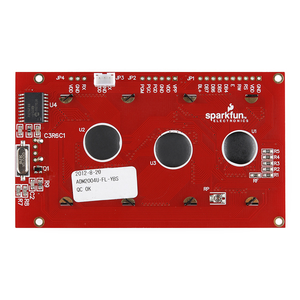
False Advertising! The picture shown for this product has the circuit board color as GREEN. But when I got the board, the circuit board color was and still is RED! Fix the picture!
Dude, relax.
Breath, breath.... "Ummmmmm.... Ummmmm...." Okay, relaxing....
Hi i erased the f/W by mistake. The SerLCD v2.5 source code is for 16F688 but the micro i have on my board is a 16F88 !! Do you have somewhere the F/W corresponding to 16F88 ? Best regards
I have 3 of these. They are so unreliable, even after applying the various strategies described by earlier commentators, that I have given up on them. I will give them away to anyone who will pay for postage (from Canada).
When I get replacement displays, they will not be from SparkFun, whom I no longer trust.
Since still can be googled, that this display wouldn't be worth the few bucks it costs due to the problems, some folks had with it:
I have now more than a hand full of them all working seemlessly, following the four simple rules for that cheap but price-worthy display:
A) feed them from sufficiantly "stiff" power source (Low ESR 100�F in 5 V output) B) Add a sender-side pullup resistor to 3,3 V for the Rx line. C) Add a procedure on the controlling mic, in which the user holds a button down during startup, if the display eventually lost its baud rate setting displaying any shit but no chars. Which does: Start from 2400 Baud, set the LCD Baudrate to your standard one. End up talking with 38600 Baud to the display, setting your standard baud rate. Any time the customer has a messed-up display, he repowers the display holding down that start-up-Button, and: LCD is displaying properly again...
To me, this display really is competitive to others of nearly the same specs, coming from Canada for double the price. It is really good readible in full sunlight and with low power consumption led backlicht also in the complete darkness.
My wish to sparkfun: Make the contrast adjusteable via serial command, not by potentiometer...!!!!! Really serious wish: Buying a lot in future, if that maybe possible.
Could you guys please update the eagle files with the newest schematic and a new datasheet with mechanical drawings? Also, did you keep the relative location of mounting holes relative to each other from the original "basic" display?
I think SparkFun needs to add a pull-up resistor on pin 4 (Vpp). This pin is an input (not input/output) and should not be left floating. Another pull-up on the RX pin would also be advisable.
My main bitch is that "|", 7C, the vertical bar character is not there. However, it IS the command character. When porting code from a previous design that used parallel LCD I/O, I "inadvertently" sent a whole s**tload of strings that were interpreted as commands and the units were not even able to be resurrected by SparkFun techsupport. This is also apparently true for all Serial LCD units based on the Sparkfun Serial-LCD Backpack module though whether it kills the unit so permanently is unknown to me.
Sigh, so I gotta buy a couple more displays.
can I drive the RX with 3.3V?
I first had problems using this serial 20x4 LCD module via software serial (bitbanging). It is controlled from a Leaflabs Maple Cortex M3 processor, which output pins are turned to floating state during flashing. Really ennoying in development phase: Hundreds of random chars appeared on the display, changing the baud rate, changing the setup as 20x4...
Cure: External 10kOhm Pullup resitor on the TX-line to 5 Volts. (Use a 5 V tolerant pin on the maple for the serial communication to the LCD.
Now: Flashing the MIC, resetting - without any problems with this LCD.
Criticism: such pullup could have been implemented in the LCD design. Designed as a Voltage divider to meet the 3,3 V TTL specifications of most Controllers around.
Further: Where is a reset Pin for the PIC driving the LCD? Bad Documentation.
I got this LCD working, and it looks lovely. Here are my recommendations:
(1) Don't buy this unless you don't mind a very slow display. Any kind of text animations or quick updates aren't going to work. Each statement you send needs to be followed by around 100ms delay.
(2) If you do buy it, use http://www.arduino.cc/playground/Code/SfLCD2 as suggested by Member207599 and add a delay(1000) to the first line of setup, so that your Arduino can finish booting up before the display, avoiding some frustrating errors others have experienced above.
(3) Set screen brightness to 10% - plenty bright and more reliable
If you need a faster display, use a regular parallel interface. If you need more pins buy an arduino mega. If your spending all the, spend the money.
This LCD is a huge pain to control but using the link posted by Member207599 its now a breeze. Documentation is fair at best as well/
Using the LCD with an Arduino board I first had some difficulties to get it to run and figured out that it needs plenty of delay(). A good lib is http://www.arduino.cc/playground/Code/SfLCD2 which does the right amount of delay after any command and now the LCD works 100% reliable with two shields in between and 15cm cable.
So many problems. The data sheet is minimal and misleading. Expect to power cycle many times to get your text to print properly
i am using a picaxe to control this display and i can send text and change the display type and back light level but i cant get any of the extended LCD commands i.e. clear display to work. I think it to do with the syntax on the picaxe?
serout 1,T9600_8,("Hello World!") and
serout 1,t9600_8,(124,140)
work but how do i clear the display?
Ah it is serout 1,T9600_8,(254,1). the data sheet could be more explicit in saying that the extended commands use 254 as the special control character. "254" is only mentioned once.
I have two of these, purchased several months apart. One appears to be working happily off the serial output of a uMFPU math chip. The other worked for a while, then could't manage the switch to the default 9600 on power off/on in a reasonable time frame (development has a lot of compile/test/edit/repeat cycles and each cycle needs a board power cycle as well). Not sure what changed, but it's an annoying glitch. Had I only needed 9600, the K107 serial board from wulfden would work fine with a display I already have.
Any chance to get some 20x4 3.3V LCD panels? As you know, by your frequent "out of stock" status, the Netduino community is growing quite fast. Would be great to have some store bought options.
This display doesn't operate the way that it is described in the Datasheet. It's pretty much worthless.
The datasheet doesn't seem to mention the vertical spacing of the mounting holes. This is 2.15" on the older version with the daughter board. The mounting holes are too small for a 4-40 standoff. Too bad SparkFun doesn't offer a 2-56 standoff kit to go with this.
My older version with the daughter board runs just fine off of the 5V pin on the Arduino at the default backlight level, which is plenty bright in a well lit room and might be too bright in a dimly lit area.
When I received mine, it defaulted to 4800 baud instead of the expected 9600 as shown in the datasheet.