- Home
- Product Categories
- Components
- Relay SPDT Sealed - Mini

Relay SPDT Sealed - Mini
Replacement: None. We do not have a direct replacement for this relay. This page is for reference only.
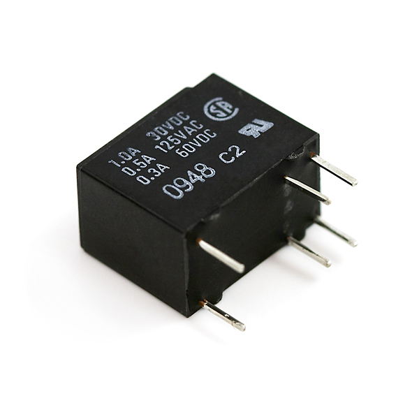
These are tiny 5V coil 1A Single Pull - Double Throw (SPDT) sealed relays from Omron. If you're looking to save space - these little guys will do it!
- 5VDC coil SPDT Relay
- Rated up to 24VDC @ 1A
- Fully Sealed
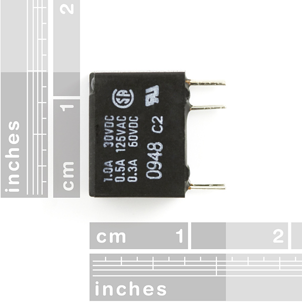
- Easy 0.1" spaced pins
- Omron part # : G5V-1-DC5
Comments
Looking for answers to technical questions?
We welcome your comments and suggestions below. However, if you are looking for solutions to technical questions please see our Technical Assistance page.
Customer Reviews
No reviews yet.
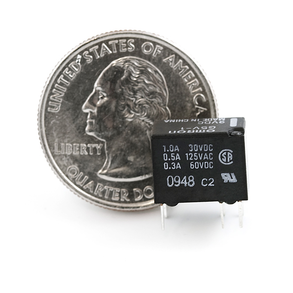
These are not 5VDC, rather 9VDC. You can see the top label in the picture with the quarter. I have some and 5VDC is not enough to make them switch.
If you read the datasheet the coil can be driven by 5v @ 30 mA, and 3v @ 50 mA
Note that this will not fit on a breadboard. :( It's small, but not what you want unless you're designing a custom PCB. The feature marked "Easy 0.1" spaced pins" made me think it would. Guess I should have looked closer at the drawing.
Sadly, it's the PERFECT relay for Arduino. It has internal resistance to draw the perfect 30mA of current when hit with 5V. Too bad it won't fit. :(
Glad you pointed it out. Even after looking at the spec sheet I didn't immediately get it. The rows of pins need to be 0.3 in apart to fit a standard DIP spot. These are 0.2. Why?
The recommended method of driving relays with the Arduino (or any microcontroller really):<br />
<br />
http://www.arduino.cc/playground/uploads/Learning/relays.pdf<br />
<br />
Any1 has tried using this with the arduino? I was wondering whether the current provided by the pin is just enough to energize to coil..
could you explain a little more calle? If I put power through pin 2 to pin 9 (or vice versa) that means that depending if the power is on or not pin 1 or pin 10 will be connected to pins 5 and 6?
You connect it like this:
http://pastebin.com/Tj9DHsXy
(you cant have several spaces after each other on sparkfun)
I just want to confirm that this is "RELAY-2G5Q (RELAY-2)" from the SFE footprint library?
I could also use some simple instructions on how to wire up this relay. Thanks!
Does anyone have a tutorial on getting these to work with the arduino. What I am having issues is:
You have 3 pins for each throw. So I assumed that you just wire the load across the 2 outer pins then hit the middle pin with 5v.
No luck though? Anyone know what I am doing wrong?
Thanks!
Sounds like your assumptions on the pinout and/or how a relay operates is incorrect. The datasheet has a little picture on the third page of the pinout. The little square between pins 2 and 9 (middle pins) is the coil - one side would likely be your digital out pin, the other side probably ground (assuming the arduino can drive the coil directly). Pins 5&6 (the 2 on far from the others) are connected together internally and would be the common side of the switch (put +5v here maybe). Pin 1 is the normally closed (NC) throw and will be connected to pins 5&6 when relay is not energized, when the relay is energized, pins 5&6 will be connected to pin 10. Your load would likely be on pin 10 on one side and gnd on the other. In that case it would be disconnected normally, and connected to V+ when the relay is energized. (See picture in datasheet for pin numbering - continuity test between pin 5/6 and 1/10 can be helpful too if you just want to check which pin is NC and which one is NO).