- Home
- Wall Clock Controller - PIC 16F877A

Wall Clock Controller - PIC 16F877A
Replacement: None. There is no direct replacement for this board. This page is for reference only.
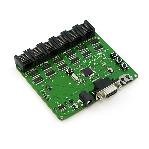
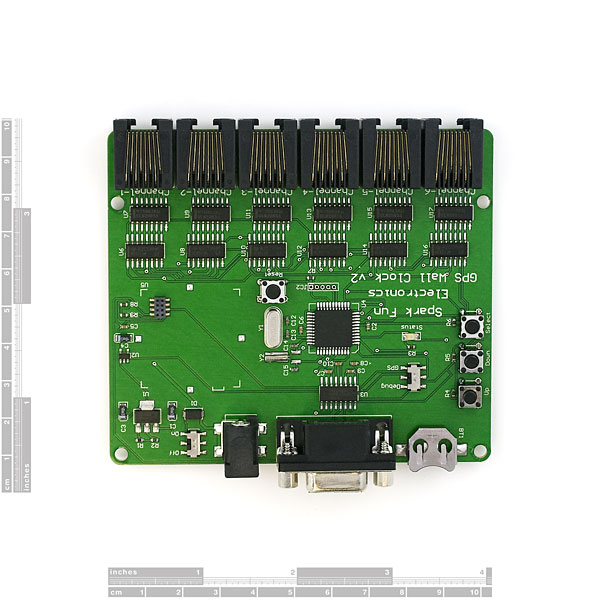
The Wall Clock Controller from Spark Fun Electronics. This board was specifically developed to control the 24" Wall Clock project. It is a very good demonstration on how to use decoders and drivers to control a very large number of IO lines. Board can be used to control up to 42 devices. Each device can use up to 500mA of current!
The board comes fully tested assembled as shown. If you are planning on displaying GPS time, we recommend you also purchase the Lassen iQ GPS receiver. Board contains the PIC 16F877A TQFP with pre-installed serial boot loader, RS232 connection for debugging and programming, and 20MHz oscillator, and 32.768kHz RTC oscillator circuitry. Three general input switches are available: labeled 'Up', 'Down', and 'Select', they can be configured for any use. With the external 32kHz oscillator, this board can be used very accurately as a clock without the need for GPS.
Board controls 6 RJ45 ports with 7 output channels per port, and one raw-voltage feed line (8 total wires per jack). Each jack accepts an RJ45 cable (also known as Ethernet or Cat-5, Cat-5e, Cat-6, etc). Each channel uses a Binary-Coded-Decimal decoder (part #: 74HC4511) to decode the binary number into a 7-segment display. These 7 channels are then controlled through a ULN2003 7-channel driver. For each individual RJ45 port, you can sink 500mA on 7 channels. This means you can control 6 * 7 or 42 different devices - each of which can use up to 500mA! We used this massive power to control 42 different LED light bars to create the giant GPS Wall Clock.
We provide example C code only. The example code will show you how to:
- Parse the incoming GPS strings from the Lassen iQ
- Output binary numbers to individual channels
- Read the input switches
- Report status over RS232 Serial
** Software:** Example Firmware is available on the GPS Wall Clock project page
Comments
Looking for answers to technical questions?
We welcome your comments and suggestions below. However, if you are looking for solutions to technical questions please see our Technical Assistance page.
Customer Reviews
No reviews yet.
Has anyone used this Controller to build a clock? I bought one and am building my clock, but need help on the programming side. If you have found success, could I please use your program. Thanks, kris
Soooooo close...
Why oh why did you use BCD to 7 segment decoder latches? Had you just used straight latches this would have been a general purpose board and it could have been used as a clock driver with the micro doing the BCD to 7 segment translation. Oh well, I have CPLDs programmed up and ready to go to replace the decoders when mine gets here (and 30 relays ready to drive).
Maybe next product?
Why is there no link on firmware, and also could you post EAGLE files?
This site is missing action shots...
See the full project page:
http://www.sparkfun.com/commerce/present.php?p=GPSClock-1
The UNL2003A is only spec'd for 2.5A total sink so its misleading to imply all seven lines can be run at 500ma simultaneously.