- Home
- Product Categories
- Sensors
- Triple Axis Magnetometer Breakout - HMC5843

Triple Axis Magnetometer Breakout - HMC5843
Replacement:SEN-10530. We are no longer carrying this breakout board but we do carry a breakout for the HMC5883L, which is a suitable replacement in most cases. This page is for reference only.
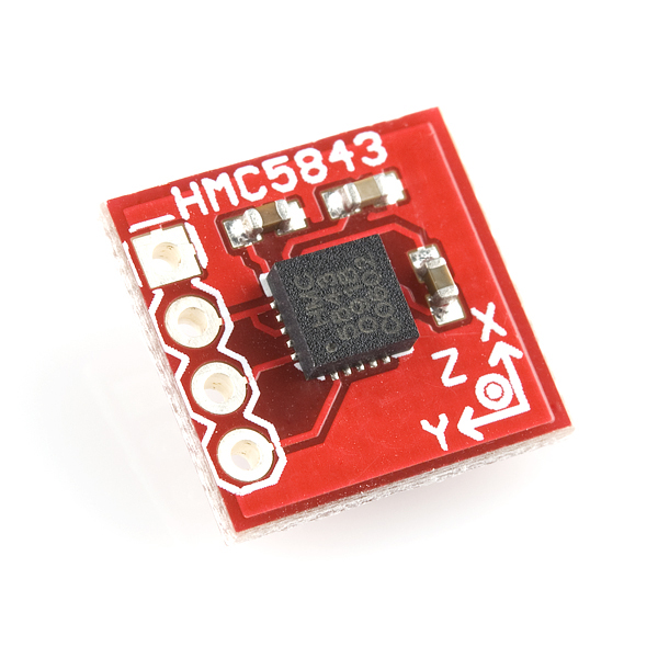
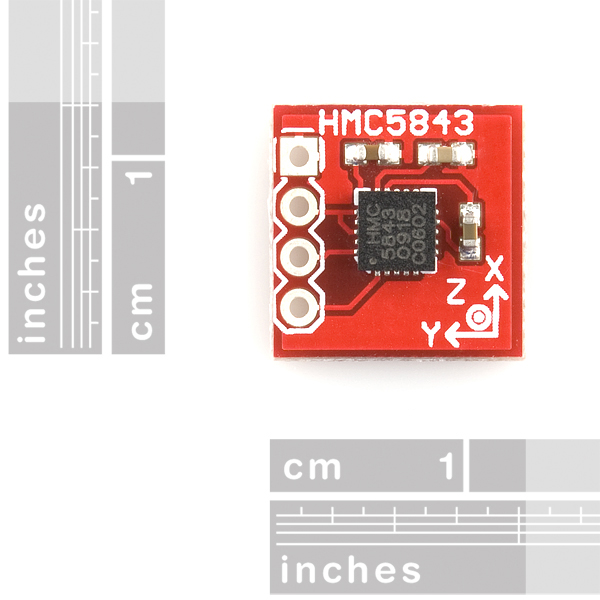
This is a breakout board for Honeywell's HMC5843, a 3-axis digital compass. Communication with the HMC5843 is simple and all done through an I2C interface. There is no on-board regulator, so a regulated voltage of 2.5-3.3VDC should be supplied.
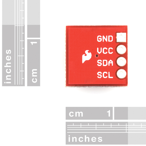
The breakout board includes the HMC5843 sensor and all filtering capacitors as shown. The power and 2-wire interface pins are all broken out to a 0.1" pitch header.
Note: We found these in inventory and they work fine but we're no longer making them. We'll be selling them at a discount for a limited time but when they're gone, they're gone!
- Simple I2C interface
- 2.5 to 3.3VDC supply range
- Low current draw
- 7 milli-gauss resolution
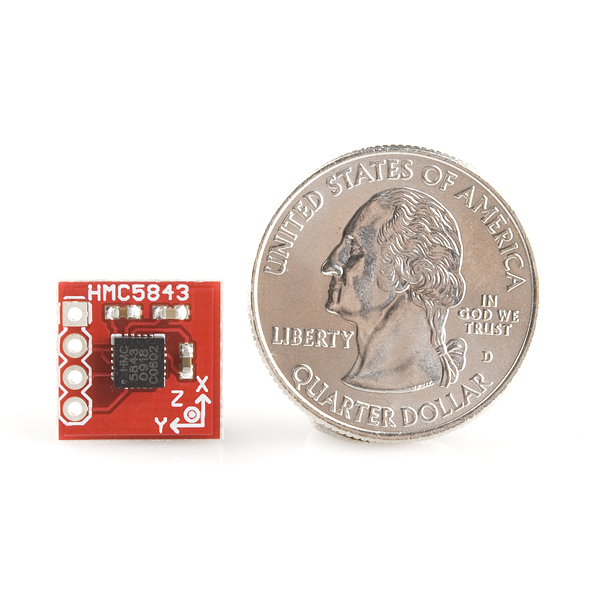
0.5x0.5" (12.7x12.7mm)
Documents:
- HMC5843 Datasheet
- Example code (ATmega328)* mbed Example
Triple Axis Magnetometer Breakout - HMC5843 Product Help and Resources
Comments
Looking for answers to technical questions?
We welcome your comments and suggestions below. However, if you are looking for solutions to technical questions please see our Technical Assistance page.
Customer Reviews
No reviews yet.
http://forum.sparkfun.com/viewtopic.php?t=15563
Here is a forum post by me (Faraday's Cage == taktoa@gmail.com == taktoa), but I also sent in a request via the "feedback" form.
Oops, forgot to say that I wasn't sure who to email, so I commented instead.
Sweet! I was the one who suggested this (multiple times a while ago). However, on digikey the chip itself is only $20? Am I supposed to believe that the various support components and tiny board account for $30? Maybe the price will go down.
Contact Sparkfun and point out where you suggested it. They might give you a free one.
Did anyone of you ever had the problem that one or two axis are in saturation (-4096)? Is it possible that this chip is defect? The Self-Test fails because of the -4096. My software works correct because i tested it with another HMC5843.
And what is the "Positive bias configuration" good for? Only for the Self-Test or can the axis get out of the saturation by using this function?
Could one single Arduino (UNO) as a master connected to four HMC5843 as slaves in a I2C serial connection? Can the address of the HMC5843 be modified so that mutiple of them can be on the same bus? If not, which compass/ magnetometr has that feature? thanks
Just a note that would have saved me a lot of time: Those using this with the Arduino Wire library, you need to use the 7 bit address, not the one (8-bit) provided in the datasheet. That is: use 0x1E as the device address, the library appends the R/W bit (resulting in 0x3C / 0x3D). Hindsight is 20 / 20...
Hi BenB,
I thought the same thing about it. I've got the problem with HMC5843 too. I am attempting to read Device ID address which is 0x48. No luck. ( I am using zilog kit microprocessor). Compass doesnt acknowledge the 7-bit 1E address (I sent full byte) but it acknowledges the 3C and 3D addresses which are 8-bit each. So far, dont know how to send 7-bit only address, unless I have to rewrite i2c communication code. I know that 1E is in 3C and 3D by shifting !E to left by one bit.
I have a problem with z axis on this chip, x,y axis work fine but z seems to be saturated to F000 !! <br />
<br />
This is the second chip i bought and both did not work on z axis :(<br />
<br />
The first one was also affected by the bad capacitor design<br />
<br />
Has anyone experienced such behaviour ?? z saturated to 0xF000 ????<br />
<br />
<br />
Is this chip 5V I/O tollerant?
Can anyone tell me which capacitor is C1 (the 4.7uF) on the actual breakout board. Is the the capacitor directly across from the headers?
Why no use of either the internal pull ups or external ones as per the datasheet?
How this will be affected by tilt?
A little note on the schematic of an ST Micro board [steval-mki062v1_schematic.pdf] mentions that the HMC5843 chip should not have a ground plane beneath it. The datasheet does not mention this. Does anyone know if this is indeed a requirement?
Hi,
I bought one last week,
i have the same problem with the new breakout. the data readed are constants..
The new board contains the batch of 4.7 ?F? i'm missing something?
Toward the end of these comments Nate says that the capacitor problem has been fixed. However the schematic linked to here still shows the 4.7 capacitor. Is this just an out-of-date schematic?
thanks
Joe
The v11 breakout had a 10uF tantalum cap that was causing problems for some but not all users:
http://www.sparkfun.com/datasheets/Sensors/Magneto/HMC5843-v11-schematic.pdf
This problem has been fixed in v12 by replacing the 10uF tantalum cap with a 4.7uF ceramic cap.
Sparkfun Guys,
You would make a much, much better board if you bring our the DRDY pin to the header - there is a good reason that Honeywell decided to bring out the RDY bit (SR0 of the Status register) to a separate pin and it is pity that you did not do the same!
Having the DRDY pin available would make asynchronous (interrupt-driven) reading data from this magnetometer much, much easier; for now it is quite cumbersome...
Doing a rev that has the DRDY pin broken out to a header would be nice. If you have any other suggestions for a rev send them to techsupport@sparkfun.com
I received a copy of this part just yesterday, and was able to get this part talking to my Logomatic. It works fine for me, spinning it on a turntable generates the sine and cosine signal I expect.
I guess that new cap works fine.
Good to know, I have heard people say this is a tough compass to use even without hardware issues.
Does anyone know if the capacitor problem has been fixed with the latest boards?
Yep. The PCB was updated in February, 2010. The tantalum capacitor was replaced towards the end of March. All boards are fully tested before they leave production.
Another input.
Somebody has attempt to use it at low temperature? (~0?C).
I have to solder the extra capacitor, but at low temperature, I tried several capacitors and the magneto doesn't work properly, it has the same behavior without the extra cap.
Digikey PN PCC2395CT-ND / ECJ-1VB0J106M
Panasonic ECG Ceramic 10uF 6.3V X5R 0603.
Small, lowESR, and makes the thing actually work well.
My 47uF electrolytic can didn't work as well - it would work for a few minutes then stop. This one from Digikey just runs and runs.
Just got two-- work fine after adding an 0805 10 uF ceramic in parallel with the present cap.
Another interesting thing - probably too slow for commercial use, but it does pick up credit card magstripes.
It works! Of course there is now a huge normal electrolytic cap (47uF) larger than the chip hanging off the existing cap/stack.
My recommendation to anyone getting this board is to have a cap ready to solder on and if it acts at all strange, add the cap.
(Come on SparkFun - don't you test these things?)
One more note on I2C - I have a compliant high speed assembly driver for ATtinyX5 chips. It does NOT work with this chip unless you add a small delay for a larger setup time before the clock line is pulsed. And it isn't just the ACK on reads (which will return 0xff after the first) - putting delays only there (to insure it would be acked) didn't help, it needs the delay for every clock pulse. (On the scope, the waveforms are compliant, and the arduino version seems to just have a long risetime v.s. the very square ATtiny waves on my setup).
Does almost the same - compiled the test code and I get x=32, y=-1 x=-1 with a few glitches.
I'm using a 3.3v arduino pro and changed the program to 8Mhz (that was the only change).
There are two caps stacked, so I assume that has been fixed, but I'm not getting any magnetic readings though it is communicating.
Adding in something, the ID bytes work. The status register is always 4 (regulator enabled, zero conversions ready). The command registers (even after being written to) read the defaults of 0x10, 0x20, but the mode register reads 0 or 1 depending on how quickly I read.them.
One slight problem - it will only read 1 byte, ie. if I send 0x3d then try to read 4 bytes, the first one will be correct (from the corresponding register), but the rest of the bytes read as 0xff. I'm doing 400khz clocking.
I saw the test code can just read sequential bytes.
I don't know about the commands - I might need to send them sequentially too.
Is anyone else seeing this?
Hi,
The datasheet says that the I2C lines of this device are nominal 3.3V... I would appreciate an advise or share comments regarding interfacing this magnetometer with 5V dsPIC MCU.
Thank you!
I was able to talk to HMC5843 chip using an arduino mega, with built-in pullups to 5V. Communication seems fine, but I cannot get the right measurements ( seems like the problem with capacitor or something - i have to investigate it, though I tried putting in a 460uF electrolytic, with no luck. Will try ceramic)
It seems the capacitor problem may be fixed in new ones. I got one yesterday that works without modification.
I wrote an Arduino library to interface it: http://eclecti.cc/hardware/hmc5843-magnetometer-library-for-arduino
The current revision of this board has a potentially incorrect capacitor.
I was unable to get it to work with either of my Arduinos and there are a few forum posts detailing the problem.
http://forum.sparkfun.com/viewtopic.php?t=17475&start=18
A newer revision is in the works but there isn't an ETA on it (as per a support email I received from SparkFun on 2009-11-11). The workaround is to replace the capacitor with one like this:
http://www.sparkfun.com/commerce/product_info.php?products_id=96
chris.
For those having problems reading data in continuous mode read page 18 in the spec... the the 5 milli-second power-up time is important!
from page 18:
To change the measurement mode to continuous measurement mode, after the 5 milli-second power-up time send the
three bytes:
0x3C 0x02 0x00
This writes the 00 into the second register or mode register to switch from single to continuous measurement mode
setting. With the data rate at the factory default of 10Hz updates (100 milli-seconds interval), a 100 milli-second delay
should be made by the I2C master before querying the HMC5843 data registers for new measurements. To clock out the
new data, send:
0x3D, and clock out DXRA, DXRB, DYRA, DYRB, DZRA, DZRB located in registers 3 through 8. The HMC5843 will
automatically re-point back to register 3 for the next 0x3D query, expected 100 milli-seconds or later.
The datasheet, if I read it correctly, says it loops back at register 9, the status register, not 8 (i.e. read the status and if data is ready it will wrap and read the data).
Done as what you said, but same problem exists. Thanks anyway. Maybe I will try another board to see if similar problem exists.
I have bought it. Seems the I2C cannot work! I am using the AVR MCU. After the SLA+R or SLA+W is trasmitted, and NACK is always received. Any suggestions?
BTW, in the HMC5843 datasheet, it says the C1 and C2 should have low ESR. It seems C2 is 0402 which may not have a low ESR.
I also had problems with the I2C not responding probably. I added another capacitor in parallel with C3, I used a 100uF because I had it to hand. I have had no problems since. I tried this because the same fix was reported on a couple of forums - diydrones and Surveyor robotics.
Although I can clock the data out, I had another problem. The X axis data is most of time negative, while the Y axis data is usually positive. But this should not be the case since I put it on the horizontal plane and rotate the board, which means the data should half time positive and half time negative. Have you experienced the same problem? Thanks!
I dont believe I have that problem since I can calculate the bearing correctly - at least a 2axis bearing, still having problems calculating a 3axis bearing.
Are you holding the board flat? That can affect the reading.
I init the chip by reading the id registers for H43 and then setting reg 2 to 0
To read I read 1 byte from reg 9 and send a i2c stop.
If the value back has bits 0 and 2 set, I then do a read of 6 bytes (without sending a reg), i.e. i2c start, write 3D followed by 6 reads. Make sure the reg 9 read and the last read of the 6 reads are naked rather than acked.
I also see what you said at AVRfreaks, but I only have 10uf Tan cap at hand, and I tried to parallel one to C3. But it still not work! Do you use a 100uf Tan cap? Thanks!
It wasn't a tan, it was a big electrolytic.
It works! Thank you so much! I also used a 100uF electrolytic cap now.
This might shed some light on the issue.
From the datasheet:
The two external capacitors should be ceramic type construction with low ESR characteristics. Reservoir capacitor C1 is
nominally 4.7 micro-farads in capacitance,
...
Low ESR characteristics may not be in many smallest size SMT ceramic capacitors (0402), so be prepared to up-size the capacitors to gain Low ESR characteristics.
I have a custom 4-layer board that uses this chip that I should get in the mail today. Assuming I can solder it without ruining it, I provide more feedback on the cap size I used and it's ESR.
My custom board works fine with a 10uf ceramic chip cap. I wonder what the ESR of that tantalum cap is on this board? My layout is about the same except I have a 4 layer board. My guess is that this chip prefers a ceramic cap.
Yes, the problem may be the tan cap, which is 3 ohm from the datasheet. I also ordered ceramic cap to replace that tan cap. I will see if it works or not.
The sensor did not operate properly until I put 100 uF capacitor in parallel with capacitor C3 as suggested in this thread. Does SparkFun have plans to replace capcitor C3 with the one that works?
Hey fenghua9801,
Sorry to hear you're having trouble with this little guy. If you could send us an email, with as much information as possible about your setup, we'd be happy to help you get this figured out.
-techsupport at sparkfun dot com
Thanks! I will first try to fix it. If it does not work. I will contact you.
You have to look at manufacturing and assembly cost. Plus there are inevitable human and machine errors that lead to unusable product (notice the ding + dent products section).
These BOBs are meant for people like me that can't/won't smd solder or don't have access to reflow ovens etc.
Nagmier is right, these are evil little buggers to solder. And remember, the honeywell breakout board is $100. taktoa - email us, point us to where you suggested it, we'll send you a free one for suggesting we carry it.
Thanks.
I have read the 2bytes storage part, but I missed the ADC.
What is the actual bit resolution on this bugger?
it's got a 12-bit ADC built-in according to the datasheet and also stores each axis's values as a pair of bytes.