- Home
- Product Categories
- Wireless and IoT
- RF Link 4800bps Receiver - 434MHz

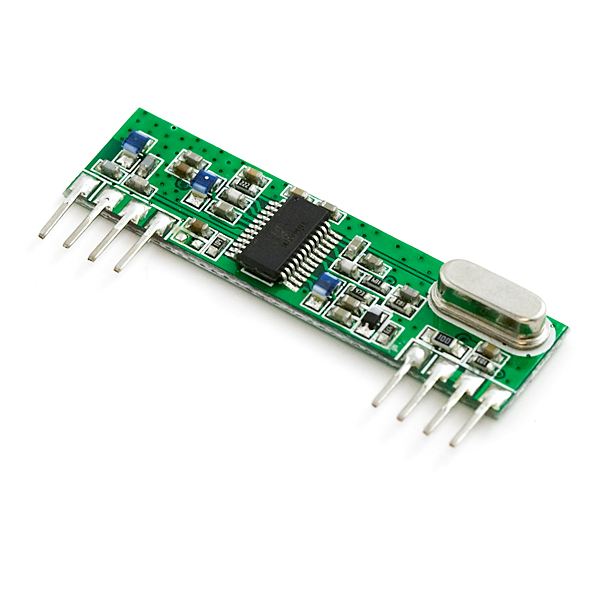
RF Link 4800bps Receiver - 434MHz
Replacement: None. We are looking for a new supplier for these, but don't have a replacement yet. This page is for reference only.
Sold as a receiver only. This receiver type is good for data rates up to 4800bps and will only work with the 434MHz transmitter. Multiple 434MHz receivers can listen to one 434MHz transmitter.
This wireless data is the easiest to use, lowest cost RF link we have ever seen! Use these components to transmit position data, temperature data, even current program register values wirelessly to the receiver. These modules have up to 500 ft range in open space. The receiver is operated at 5V.
We have used these modules extensively and have been very impressed with their ease of use and direct interface to an MCU. The theory of operation is very simple. What the transmitter 'sees' on its data pin is what the receiver outputs on its data pin. If you can configure the UART module on a PIC, you have an instant wireless data connection. Data rates are limited to 4800bps. The typical range is 500ft for open area.
This receiver has a sensitivity of 3uV. It operates from 4.5 to 5.5 volts-DC and has digital output. The typical sensitivity is -103dbm and the typical current consumption is 3.5mA for 5V operation voltage.
- 434 MHz Operation
- 500 Ft. Range - Dependent on Transmitter Power Supply
- 4800 bps transfer rate
- Low cost
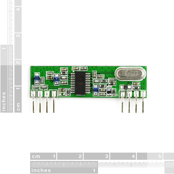
- Extremely small and light weight
- KLP Walkthrough Tutorial
- Good AVR Tutorial
- Receiver Datasheet
- Another Very Helpful AVR Tutorial - Thanks Eric Forkosh!
Comments
Looking for answers to technical questions?
We welcome your comments and suggestions below. However, if you are looking for solutions to technical questions please see our Technical Assistance page.
Customer Reviews
No reviews yet.
I've been playing with the 4800bps 434MHz modules and have gotten them working. There are a few details I discovered using a logic analyzer and I thought I'd post them for everybody's benefit. Some of this has been noted before, but it is worth repeating.<br />
<br />
1) If you let the TX data line stay low for a while it stops transmitting, causing the receiver to crank up its AGC and receive noise. Note that the noise is structured such that it will cause bogus bytes to be received<br />
<br />
2) If you let the TX data line stay high for a while, the receiver starts to receive a low value. I think the TX is still on, but the RX must be filtering our LF or DC components.<br />
<br />
3) If you send data continuously, you do not run afoul of #1 or #2. However, you should periodically allow TX to go idle for just over 1 frame time to ensure the UARTs stay in sync.<br />
<br />
4) If you do hit #1 or #2, then you will need to send some bytes to get the RX module's AGF and HPF happy with your data. At 2400bps, I found 2 bytes usually sufficient, and at 4800bps, 10 usually got things going again.<br />
<br />
5) The H->L edge latency seems to be around 33uS, but the L->H edge latency is around 100uS. This prevented me from getting the link working at 7200 or 8000 bps. The latency difference may be due to the low drive current of the RX data line. A buffer might help make things more symmetrical and allow slightly higher data rates.<br />
<br />
The algorithm I settled on is as follows:<br />
Each packet starts with a preamble of 0x55 bytes (3 for 2400bps, 12 for 4800bps), followed by a 1-frame-time gap so the RX UART can get back in sync, followed by a 0x0f start byte, then the payload data, and then a checksum. Packets are kept fairly short (~128 bytes) due to a fairly high error rate.<br />
<br />
Cheers,<br />
- Dean
Hello Dean,
i found Your reply interesting! So even there is lot written about this, i have some questions.
to point 1: do i understand it right that if i leave transmitter powered the receiver acts noisy?
I ordered this pair (in europe it is easier to get these)
http://www.sos.sk/a_info/resource/c/RX-4MM5%28650200821_sf%29.pdf http://www.sos.sk/a_info/resource/c/pdf/tx4msil.pdf
and as You mentioned, the receiver just sends random bytes. Interesting is that if i connect on breadboard the transmiter and receiver and power them up, there is no random data from receiver.
So what do You suggest to do? Should i turn off the transmitter completely and power it up only during communication? My aplication will not use this communication often but when it will be necessary, i need reliable data. i am running USART at 1200bps and my "telegram" looks like: AAh (start) 85h (address) xxh xxh xxh (data three times) 58h (check)
thanks
Please see this comment: http://www.sparkfun.com/products/10532#comment-4eaad859757b7fd35100bc4a. The bottom line is that the receiver won't lock onto the TX signal unless it is modulated (isn't steady; has many H-L and L-H transitions). The examples show some methods for doing this.
Thanks Mike,
understood. interesting thing is that if i have both on board and simulating sending data via UART tool of PIC kit, i can clearly see all the data comming from receiver. Even if i leave them for minutes inactive :)
Could anyone that has gotten this to work with an AVR kindly post how you did it? I've purchased two transmitters (WRL-08946 434MHz and one receiver (WRL-08950) and I have not been able to get them to communicate. I've tried both tx'ers (one at a time) and nothing. I know my USART communication is ok as a) I've used this code on several other projects and it's fine, and b) when i hardwire connect the TX from one ATmega328p to the RX of the other ATmega328p and open my console on the RX end, i can see the communication perfectly. I've checked, double checked the wiring and connections. I've followed two separate tutorials using these devices.
Can anyone suggest how to get these working?
On the transmitter page, someone posted an overview of how to deal with the static.
ErieRider: Duplicating my post... These modules work just fine. Just remember that the receivers have automatic gain control and will increase their gain in order to find a signal. This means that the receiver will start to generate noisy output unless you transmit something about every 10mS. I dropped the antenna from my transmitter and signal integrity on the receiver improved - I left the antenna on my receiver. Further suggestions, put some filter caps across the power supply pins and integrate a preamble byte and a checksum. Have the receiver search for the preamble and verify the packet with the checksum.
when is this going to be in stock?
It does not work good.
When the transmitter DATA IN is in LOW level,
the receiver DATA OUT holds in LOW level as well. ok!
But if the transmitter DATA IN is in HI level,
the receiver starts to flick. It NEVER
holds on HI level.
Is this normal?
The .PDF is very poor.
could you please help me to know how these TX/RX 434 MHz will work with other microcontroller such as Philips 80C51 8-bit microcontroller, how i will connect an LED so that I can verify if the RF activity is going on in the receiver side. Is it possible if we can put visual LED without any microcontroller, what is the connection then. So we need to program first the microcontroller before it works out? I tried these thing without any microcontroller, i send sync signal on the stand alone transmitter and receive it 60 ft away. I receive something but its square wave, it changes the display in the oscilloscope when i varies the frequency from 1 KHz to 10 KHz. Beyond that distance there are distortion on it. Can you help me out in where i will connect a visual LED? Thanks
im having a hard time communicating this receiver and transmitter via micro-controller pic16f877a UART mode, here is a link http://forum.sparkfun.com/viewtopic.php?f=4&t=25526
Good,
I'm waiting for some time to be able to make my order, but the item WRL-08950 is not yet in stock, hence I would like to know when this product will be received at SparkFun?
Just hooking up the receiver module (no transmitter at all), and watching the data pin with only an oscilloscope attached, I see a steady (although a bit noisy) PWM-like signal, 0-5V approx 50% duty cycle. If I attach a voltmeter in place of the scope, I read about 2.5V (as expected).
If I now transmit a steady signal, the data pin on the receiver is a clean, flat 0V.
So, I think the problem a lot of people are having is they expect the data pin on the receiver to be a high or low based on what is received. Instead you get a 50% duty PWM or 0V. This is usable, but not what I expected.
i also figured out that you need about 100ms for the modules to start up. so make sure your micro controllers wait that long before attempting to send or receive data.
i found that out while building an r/c receiver for a car. it went from barely working at all to fully functional just by inserting a 100 ms delay at the beginning of the sketch.
i've bought 2 pairs of these modules, a 315mh and a 434mhz. mainly been using them with an arduino with atmega 328. the transmitters are easy to get working, but the receivers seem to have issues.
i dont think the logic level on the receiver is 5v, i think its actually 3.5v. i used an op amp to boost the logic level. i think a mosfet would have worked better but i didnt have one on hand. if you use the receiver with a 3.3v micro controller you will probably be able to connect it directly.
use an antennae with grounded shielding near the electronics, it really helps. i used the antennae out of a fried r/c receiver and they worked fine.
Hey folks. You'll notice in the (particularly poor) datasheet that the logic output high and logic output low values are specified with an output current of 10uA. If you are using a 5v supply (which the part requires) then the input impedance to whatever chip you're trying to read the data from (an MCU or Max232 chip or whatever) needs to be about 500kOhms or more to stay at or under the 10uA specified.
I've notice that as the output current from the data pin increases, the bit error rate increases. For those of you having problems achieving more than 2400baud, check the input impedance to your microcontroller pin. If it's much below 500K? then maybe use a buffer circuit to prevent the output from getting too loaded down.
I have successfully used this module to receive 4800baud NMEA strings from a GPS.
Good luck.
Dan
that explains why my opamp hack works. i was using an opamp with gain set somewhere between 3.5 and 5, but only supplying it with 5 volts thus allowing it to clip. everything i knew about opamps said this shouldn't work, but it did. the opamp must have been boosting the current allowing my arduino to receive a bit stream (and im using the usart and not software serial).
transmitter seems to work fine. i can hear data centered on 433.900 via a icom ic-q7a.
rx appears doa though. =/ bummer!
I finally got this to work with my AVR - MEGA644PA. The trick is to setup a small delay between transmissions in the while loop.
In other words, when sending data from the transmitter, I have a delay of 2ms before sending data again. This sends data about every 10 seconds. When I had a delay of 100ms, I was never able to send anything. I am using 2400 baud.
I cant' get this receiver to work right. I get constant noise when not transmitting. I saw that you are supposed to get a signal every 10ms or it will go crazy. I am just using this to count pulses every 50ms, I can't go faster because of harware limitation issues. Is there a way around this? Some of them get 1017 on analog input for a signal found, while other receivers only get 1014. I get spikes during static/no signal that peak all the way to 1019. I have the data pins soldered together, the data pins soldered together, the power, the ground/antenna. So only 3 wires go to the micro, power/ground/data, and one wire outside to antenna. no capacitors or the like, except on the micro's 5V power supply.
Using Pic to Pic serial communications with these I can't seem to push it past 1200bps. It seems pretty stable there however. Using a DSO Scope I captured and compared the out going serial data from the pic and the output from the receiver module. They look alright at 1200bps but any faster and they go out of sync. 15 to 58 percent shorter pulses on the receiver end. Explains why it doesn?t work at high speed. Example: 1 bit on transmitter micro pin = 208us where as 1 bit on receiver output is 88us... BAD! Running at 4800bps.
The transmitter end also takes a little bit to trigger so it could also be on that end of things. Overall it works for what I need it to
Hi, I just received one of these modules yesterday and am unable to receive anything. (434MHz model)
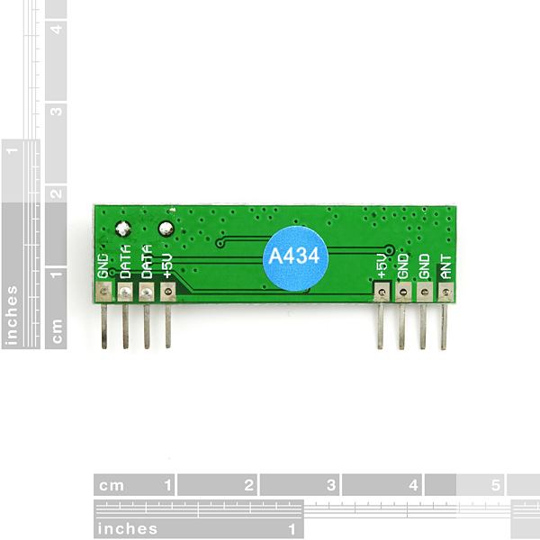
I connect the 2x +5V, 2x GND of the receiver on a breadboard, a 20cm wire as an antenna, and try to monitor activity on pin 2 (data pin) and pin 3 (Test) using a MSO19 USB Mixed Signal Oscilloscope (sold on SparkFun).
Here, I expected to get some garbage from surrounding RFI, but I have a flat 0 using the oscilloscope function and with the logic analyzer portion, sometimes I got 1 sometimes 0, but it never changes, like if the output was "tristated" or "floating".
I then tried to use an old project to send some data (it uses the TX that matches with this receiver), and I know this project works as it sends X10 RF code, and light my living room halogen up.
Then again, nothing on the receiver data pins.
Shall I assume that the RX module is defective, did you have problems with them recently ?
Thanks in advance.
SilverGhost, Did you manage to get this working?
If so, what was the problem?
I'm not getting anything out of the receiver, not even the garbage data...
Any suggestions are very welcome.
If that can help some people...
I buy this to use with a pic18f from microchip with a mikroe board, after one week, i go to be crazy because i get nothing out of the data pin.
I found the right doc and I read that the high level is 0.7*Vdd so ~3.5V -> 1 and 0V -> 0, but the pic don't get it at this level.
So I have to put one transistor command with the output data pin and powered with 5V.
And with that it's working !! UART don't work good with my case, so i use Manchester coding ( I think it is best ), and no problem now !
http://www.8051projects.net/e107_files/public/1244115299_7657_FT20623_transmitt433mhz.pdf
http://www.8051projects.net/e107_files/public/1244115299_7657_FT20623_recieverrxd1433mhz.pdf
Good luck ;-)
I tried to use the code from the SparkFun tutorial, but it didn't work. In any case, I found this site: link
Gah! I keep hitting submit instead of preview! I meant to say that I had to #include SoftwareSerial.h to get it to compile.
Also, I had to #include , but it works.