- Home
- SparkFun USB to FIFO Breakout - FT245RL

SparkFun USB to FIFO Breakout - FT245RL
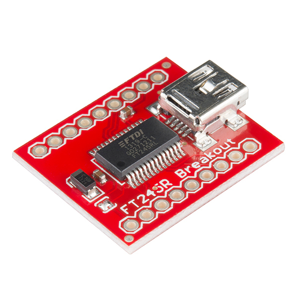
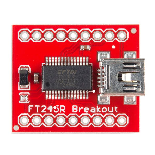
Basic breakout board for FTDI's popular USB to FIFO IC. Now with internal oscillator and EEPROM, the FT245RL is an impressive IC! This FIFO IC gives the user 8 I/O pins for parallel reading and writing.
Board comes assembled with IC as shown.
- Schematic
- Eagle Files
- FTDI Website
- FTDI Driver Page
- FTClean (for removing extraneous/old ports)
- GitHub
SparkFun USB to FIFO Breakout - FT245RL Product Help and Resources
Core Skill: Soldering
This skill defines how difficult the soldering is on a particular product. It might be a couple simple solder joints, or require special reflow tools.
Skill Level: Noob - Some basic soldering is required, but it is limited to a just a few pins, basic through-hole soldering, and couple (if any) polarized components. A basic soldering iron is all you should need.
See all skill levels
Core Skill: Electrical Prototyping
If it requires power, you need to know how much, what all the pins do, and how to hook it up. You may need to reference datasheets, schematics, and know the ins and outs of electronics.
Skill Level: Rookie - You may be required to know a bit more about the component, such as orientation, or how to hook it up, in addition to power requirements. You will need to understand polarized components.
See all skill levels
Comments
Looking for answers to technical questions?
We welcome your comments and suggestions below. However, if you are looking for solutions to technical questions please see our Technical Assistance page.
Customer Reviews
4.5 out of 5
Based on 2 ratings:
Works Great
Connected to a 68008 CPU, A copy of Katy 68k board running at 14mhz comm speed is set at 115200
FT245 makes a great serial port for a Z80
I used it as the basis for a Z80 single board computer. It's been sitting around collecting dust until now.
It's great, since interfacing to the Z80 only requires a single 74xx244 and two OR gates. Given that, you can just read and write characters without the hassle of bit-banging. It provides a 1MBit/s serial port. It supports big I/O fifos, and can even be used to trigger receive interrupts.
It's the perfect thing. Since sparkfun doesn't build it anymore, I'm building some on my own using their eagle project.
I found this really easy to get started using. I downloaded a sample C++ project from the FTDIChip-ID Examples section of the website, started adding code from the D2XX Programmer's Guide document, and it's working great.
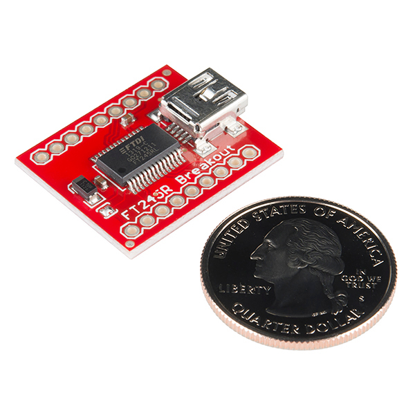
FTW, 1.5x0.92" = 38.1 mm x 23.4 mm. Metric, for Pete's sake.
Except that this can't be right. There are 9 holes at 2.54 mm pitch, so the total board length is about 10 x 2.54 mm, or 25.4 mm (1"), certainly not 1.5".
i can't tell from the photos: does this use mini usb or micro usb? also, can this be used for implementing an HID device recognized by a pc/mac/linux box as a HID device without a driver install? also, this thing is multiple years old…is it on its way out? is there a better option here for what i'd like to do?
I was wondering the same thing. According to https://www.riecktron.co.za/en/image/cache/data/products/07841-01-600x600.jpg it's a mini USB.
Sparkfun, can the next version of this BOB be with a micro-USB connector? Mini-USB is so passé.
I have to put it on a other PCB. Where can i find the footprint?
If you're using Eagle CAD, try this BOB-07841 Footprint, Eagle v5.11 library file
If not, you can manually space it: Screenshot, 0.1" grid
It looks that also the schematic is not correct. It shows 8 pin on the header as the board has 9 pins header.
If you mean the SparkFun schematic of the actual board - I think what's going on is that they're showing the I/O pins as 1 'header' JP1, with the VCCIO pin separate on the single pin JP3.
JP2 is also 8 pins, which does seem incorrect, but all that's missing is the 2nd GND pin which is connected to the first one on the board.. not a huge problem :)
Guys I want to Know whether interfacing Keyboard with Microcontroller is Possible with Break out Board (USB to Parallel Converter,FT245R)...Please post your ideas...
I'm finding this incredibly difficult to implement. It would really help if there were sample code (particularly C# sample code) for this product. I've read through a lot of documentation on the FTDI website, and I've successfully installed the drivers, but cannot find examples or instructions on how to actually USE it from a C# program. Any help would be greatly appreciated.
I'm wondering if you could use this with an iphone/ipod to pull the audio signals out - any ideas?
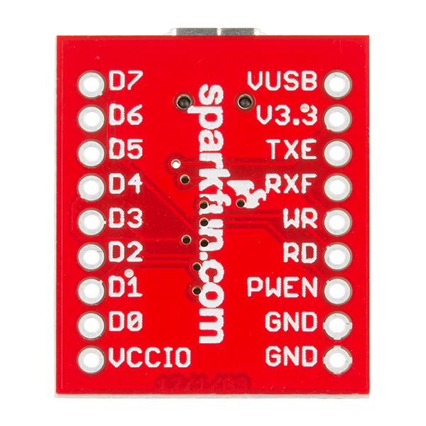
Tip for the next version of this breakout board: "Put the pin label silk screen on the top of the device and not on the bottom of the board."
The first thing someone will do is put headers on this breakout board and use it on a breadboard, then guess what, they will need to pull it out and look on the underside to confirm pin outs. Seems like a simple design idea, not sure how this item slipped by. I am sure there is a reason for it, right?
I agree that it would be more handy to have the pinout printed at the top side, but the reason why it's printed on the bottom is probably a simple one: there's more space there.
This board is really awesome. You can use it to send or receive data to any system- I have an ATMega328p functioning as a latch and simple controller for the signals.
There is only one problem though, and I'm not sure who's end it is on. I know that my circuit is correct, as well as my code (cocky but I've checked this many, many times). However, my data is being scrambled at some point. I'm not sure if it's a problem with how Windows is sending the data, or a problem involved in the pin labelling, but the data I am sending is showing up in the wrong order on the data output pins. Still, as long as you test your circuit before you have gotten to a point where this is difficult to get around, this board and chip are an awesome and simple way to send data to a system over a USB connection.
Do you have any sample code you can share (ideally, C# code)? I'm having lots of trouble figuring this thing out.
v1.05 datasheet link is broken, returns 404 error.
V2.06 is now available at http://www.ftdichip.com/Documents/DataSheets/DS_FT245R_V206.pdf.
Can you verify that the new datasheet is consistent with the FT245R on this board?
thanks