- Home
- Reflow Toaster Controller

Reflow Toaster Controller
**Replacement: **None. We're working on a revision for this board but it's a little ways out. This page is for reference only.
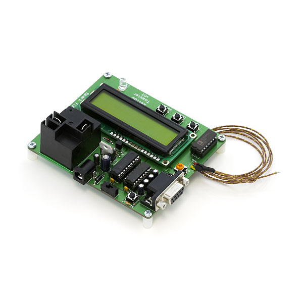
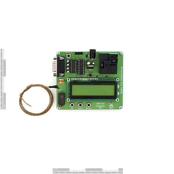
The Reflow Toaster controller from Spark Fun Electronics. This board was specifically developed to control a toaster oven, hot plate, reflow oven, or other high power device. The unit comes as a kit**** with all the needed components for a fully independent system. Runs on a PIC 16F88 with boot loader pre-loaded (no programmer required). **No system code is provided. We get you the hardware, you get the thrill of creating the control system yourself!
We do provide example C code (CC5X compilable) that demonstrates control of the LCD, reads the buttons, displays the temperature on the LCD, debugging output via RS232 to Screamer, and toggles the power relay. Relay can be mounted on PCB but we found that it is best to keep the relay as close to oven as possible running control wires back to the PCB. More information can be found in the Reflow Toaster tutorial.
As to be expected - we do not recommend this kit to anyone who is not familiar with electronics. The kit* is* entirely through-hole devices. However, when using the high-power relay, the user will need to splice into the AC power cable of the device you are attempting to control. This can be extremely dangerous causing death or dismemberment.
We cannot be held responsible for any damages caused by this kit - use at your own risk.
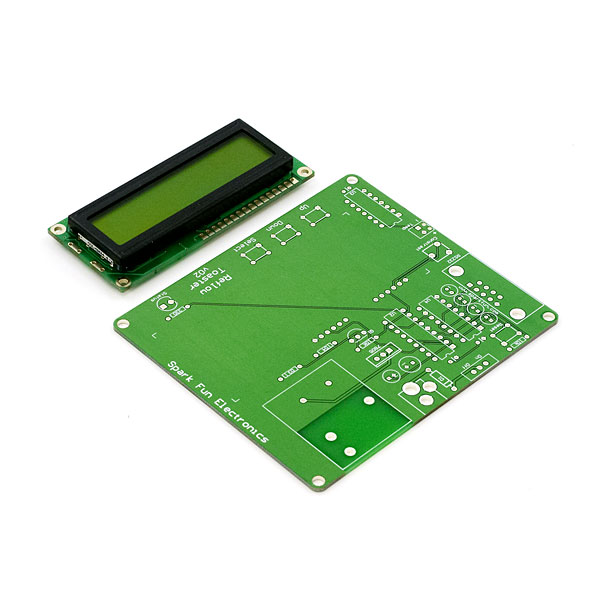
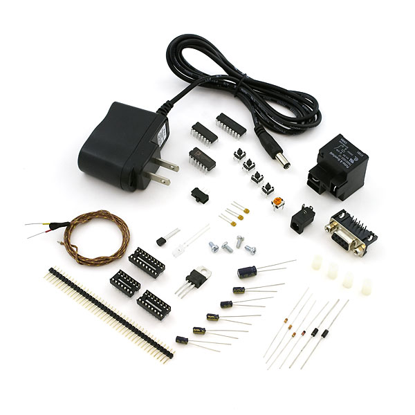
Kits Includes:
- Bare PCB
- High power SPST-NO Relay
- 30" Type-K Thermocouple
- 16F88 Preloaded with Bloader
- AD595AQ IC
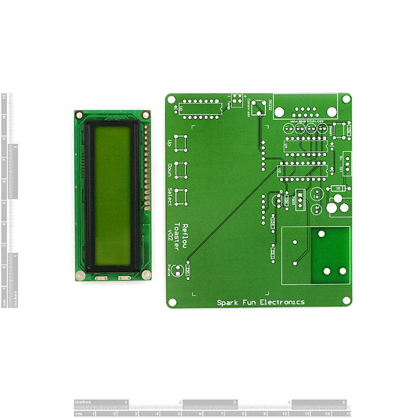
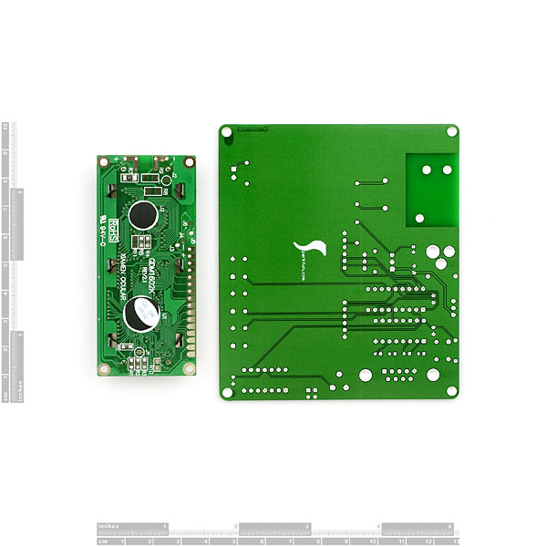
- 16x2 LCD with Backlight
- MAX232
- Wall Power Supply
- Small parts (caps, sockets, BJTs, connectors, etc)
- PIC 16F88 running at 8MHz
- Thermocouple readings from -270 to +1372C
- High power relay controls up to 220VAC @ 30A
- 16x2 LCD STN with Backlight (looks great!)
- Three buttons for menu control
- Status LED
- Reflow Toaster v2 Schematic
- Example control code (HD44780, Relay, buttons, ADC temperature, printf, printf_lcd, RS232, etc).
- Excellent Article by Kit Ryan
- PIC Code for Kit Ryan's Article
- [Revised Code](http://cdn.sparkfun.com/datasheets/Widgets/Toaster Oven Controller with All Steps 20101106.hex) to access all steps (Hex)
- PIC Loader Tutorial
Comments
Looking for answers to technical questions?
We welcome your comments and suggestions below. However, if you are looking for solutions to technical questions please see our Technical Assistance page.
Customer Reviews
No reviews yet.
So this has been retired forever yet one sits on my bench happily cooking along until the other day when it went dark.
Figured it was the PIC. Dug out the programmer, downloaded the hex file only to get the same result. Went went to compile the -v021 code only to find the include files missing or incompatible with the ones in MPLAB.
Any idea where to find the code for hex file?
Are there any plans to release another toaster oven controller to replace this one?
A few important observations to note:
1) Component layout drawing is NOT included. It's pretty intuitive, but not good for teaching your teen the how-to's of soldering according to supplied documentation in a kit. If you can read a schematic, you can figure it out via the silkscreen without too much trouble (unless you need tri-focals like me).
2) One of the caps in the kit I received wasn't the value shown in the schematic. It worked anyway.
3) The relay issue that others have noted still has not been addressed (as of mid May 2010), and required a 4.7k resistor in parallel with the 10k to the base of the transistor. I just piggy-backed it on.
4) Kit's code is the real redeeming feature here, saving a ton of time, and it's pretty slick. I observed the temperature with a 1200W, 4 element (2 top, to bottom) toaster oven and it followed the target temperature pretty impressively.
I am really sorry I bought this. SparkFun is still shipping 12V coil relays and 9V power supplies, and I don't think the PIC chip they sent has a boot loader. Instead of using this to cook up my new circuit boards, I'll be spending more money on a compiler and programmer.
2008 Nut & Volts:OvenFlow 1.0 news article => http://www.nutsvolts.com/uploads/magazine_downloads/932/OvenFlow.pdf
Comes with no documentation, and requires extra hardware and software to program. NOT A WORKING STANDALONE KIT AS ADVERTISED. If you don't have PIC programming hardware, software, and experience, then do not waste your time and money on this $90 do-it-yourself doorstop.
I can't program the PIC with the Kit Ryan code using MPLAB and Pickit 3. Would anyone able PLEASE sell me a pre-programmed PIC so I can use this thing!
I followed all steps on how to program the device and the programmer will not make connection with MPLAB, it just says connecting until I unplug the USB cable.
Thanks all,
John
For an alternative home reflow soldering solution, check out Reflowster. It's more of a device and less of a kit which may be good or bad, depending what you're looking for. It just plugs into your toaster oven and has a temperature probe for getting the profile correct. http://reflowster.com/
Anyone looking to make a toaster reflow oven might want to check out my Toast-R-Reflow project. It consists of a dual optoisolator + triac power board that you install in the oven. The optoisolator inputs are connected to a cable that comes out to a controller board that also has a thermocouple amplifier on it. The whole thing is run by an ATTiny85. http://nsayer.blogspot.com/2013/11/toast-r-reflow-how-to-summary.html
Used a 1KW Walmart 2 element toaster oven. Removed the spatter shield from lower heating element. Programmed the PIC with PICKit 2 and MPLAB v8.60, using the supplied hex file. Worked first time, no problems. Used supplied 9v wallwart; changed no resistors and had no problems with 12v relay. I've seen PICKIT 2 clones on eBay for under 20 USD.
Controller success!
Well, I've done it - thanks, Sparkfun, for a great kit! Original relay worked as designed, but bypassed for SSR (Omron 25A, G3NA-225B-DC5-24, Grainger #6C903 ~$30). Otherwise, did nothing special with kit. Used the SSR to segregate voltages (per comment by "wnm", thanks) inside of a double-gang box w/master power switch, half of a duplex outlet switched, half controlled by SSR into which I plug the toaster oven. All mounted to 1/2" 9-ply leftover plywood, see pics. Bought programmer (PGM-09671), followed Ryan's directions, fiddled a bit with programming software, and viola. The SSR needed a load on it in order to behave as expected; testing prior to plugging in the oven had me puzzling for a while. PS indicator light serves as master power indicator in this implementation.
Upon plug in, you only get blinky, nothing on screen. Program the PIC to be useful - need SFE's PGM-09667 or -09671 or similar, then read http://www.sparkfun.com/datasheets/Widgets/ToasterOven-UserManual.pdf. Serial port is only for data logging (at least when using Kit Ryan's code).
I modified Ryan's advanced code (thanks, Kit), modified by Member #158475, to duplicate program 1 (all 10 steps) into program 2 but changed the trailing sequences to be 1 second instead of 5 (copied the hex for program one, pasted for program 2, changed trailing 5's to 1's, changed the checksum digits). Please note Ryan's instructions in the manual: 1) "The program steps must already be saved in the PIC memory": do this either by changing supplied C code or editing supplied hex directly, prior to programming PIC. (Program 1 starts with line beginning with ":10420" & ends w/end of line ":10424"; Program 2 follows immediately; last two characters of each line is checksum digit - http://www.planetimming.com/checksum8.html) 2) "Setting a step timer to 0 indicates the end of the program": this means that once you set a step to 0 seconds, it and all subsequent steps will be deleted - so beware! (Is there a "big brother" to the PIC chip that might have more memory, say, 8K, so someone might add the "add step" function?) I found that if you use all 10 steps, the program continues with the last step indefinitely, so I have set step 9 to 0 seconds in both programs. Will also send hex code to Sparkfun, "maybe they will post it." (No warranties implied.)
RE thermocouple: type K= yellow positive, red negative. Soldered it in, clamped it down to plywood aka strain relief using rubber washers, see pics. If you want terminals, order PRT-10571.
Oven: purchased Oh-ster TSSTTV0000, ~$40/sale/Tar-chez; online item #13423345, not convection. Set to Toast/Bake, 450/max temp, & plug into controlled receptacle - no hack required. Enclosure says 1400 watts, website says "1200 watt output", Kill-A-Watt meter says it draws ~1250 w/four burning. Does fairly well w/heat profile (leaded solder), but wish I had full 1500 watts (= max retail device) to help hit the peak more quickly (does anyone know of one?). Had to use additional step in program at same peak temp (220C, 25 sec) to give oven time to hit it. Believe convection models detract from heat, because circulating air would transfer more heat to/out the enclosure & dissipate. However, if we had a pin-compatible PIC with more memory, it is conceivable that you could hack a convection oven to turn on the fan in the cool-down cycle, which would be far better relieving stresses caused by overcooling (read open the oven door). Alternately, screwing COM-09648 or -09649 to the side of the enclosure w/stand-offs would probably work well, as there are perforations which would allow cool air to be introduced. RE leaded/unleaded, don't know if these ovens have a thermal safety: Kester peak temp lead-free 235C to 255C=455F/491F? Mind you, I'm hoping to build Christmas decorations of heirloom quality w/50, 100 years L10 life, so longevity is priority, hence lead.
For data logging on Mac w/no DB9, ordered CAB-11304, but had to remove hex nuts from controller's DB9. Could not get nuts off of the cable! Cable should have male screws, not nuts. Not good for grounding reasons.
I could be persuaded to program your PIC with modified 9-step OvenFlow code in both programs; email me at PICProgram at wi dot rr dot com.
Many thanks, Nate - and thanks again, Sparkfun.
Erich81 . I am interested to hear more about your SMD implementation .
I built the board and the LED flashes periodically. I connected the board to my computer with an FTDI cable (it is just a usb-to-rs232 interface cable). By using an RS232 communication program (PuTTY) I am getting the "OK" on the terminal. I don't see the Sparkfun logo on the LCD and the board offers no functionality. I believe this is how it is shipped.
I have no idea how to download any of the programs provided above (I have been using AVR's and I have no experience with PICs and I don't have a PIC programmer).
So, can somebody tell me how to download the "Revised Code" shown above using the bootloader, if this is possible. Ryan Kit says in his tutorial that the bootloader provided by Sparkfun can handle files up to 2K. The tutorial dates back to 2008, and I hope this is not accurate, because I would have to find a PIC programmer which I would like to avoid.
A few thinks I tried are: 1) I download the Windows XP Hyperterminal, and I tried to use the option to send a file to the RS232, but that didn't work. 2) I found this bootloader http://www.etc.ugal.ro/cchiculita/software/picbootloader.htm and program. Of course, I have no programmer to download the bootloader program provided on the website. I get the OK's on the "Terminal" tab, but the program doesn't recognize the device, and it cannot program it. I believe this is because it needs the corresponding bootloader that can communicate with this program. 3) I downloaded and installed MPLAB IDE v8.85. I see that there are several programmers supported, but I couldn't find an option to download a program on a PIC using RS232 though a bootloader.
To summarize: 1) Can somebody tell me what software I need on my Windows 7 computer to load a hex on the PIC by using RS232 and the booloader that is on the PIC? 2) Is there some sequence of things I need to do to download a hex on the PIC (such as press reset, or power up the device while having reset pressed and then send the file, etc)?
Thanks a lot!
Did you ever get anywhere? I built this "kit" as well and am left frustrated. The led flashes periodically, the display lights up and with contrast adjustment turns the display to solid blocks, other than that nothing.
It says it comes pre-loaded with BLoader, but there is no documentation anywhere that I can find on how to use it to load anything, including the files they link to in the description. There are several unanswered entries in the forum so that doesn't help much.
There are no instructions on what exactly is required to even use the files in the "example control code" zip file. While I'm familiar and confident enough to tear apart and hack into a toaster oven voltage and component wise, I've no clue on using pic as it's something I've never used before and the overall documentation and instructions for this kit have left me very confused and frustrated.
Looking at the schematic it appears that a 12v source is OK and I'm using that too. Had no problem programming the chip with Ryan's code using a PICKit3 and MPLABX for OS X. I'm going to finish testing the setup tonight and don't expect problems. The through-holes on the board are brittle. The product is cool - but it'd be killer if it was ATMega, SMD, and USB instead of rs232.
I nearly ruined the thermocouple connection on the board because I got them mixed up by referencing the picture. At first I was going to say "it's probably my fault" but the more I look at that photo - the thermocouple wires are pulled down over two holes that have no reference in photos or documentation. It would be nice if there was a connector that would have made things more obvious - that would also allow thermocouples to be replaced when worn. However, differing alloys between the board and thermocouple might complicate things. At the least it would be nice if there was a note about connecting the thermocouple to the board (where, how) since it's a slightly different beast than a typical copper connection. A photo and note would suffice.
relay voltage - I solved this by buying a 12VDC wall wart. vinfinity EPS120050 from Digikey. No worry about 9V on a 12VDC relay.
But my board didn't come with terminals for the temp probes. And I cannot figure out how to get code into the thing through the serial port. I get nothing on the screen but I get OK over and over on the serial port. Would it cost so much to put some instructions here on how to get code into the PIC? I have MPLab that I'm used to using with ICSP and Pic24s, but danged if I can figure out how to use it to load code into this via Serial cable.
I did my first SMD project today. It was only a breakout board for a hall effect sensor that was using a sot-23 package. To solder the board I used a ten dollar electric skillet I bought at Pamida. It worked great the first time. I used a tooth pick to apply the solder paste. So I am wondering why do people want to spend a hundred dollars or more for something a ten dollar skillet will do just fine?
I decided to try a different computer running an older version of MPLAB and was able to program the PIC16F88 with the Kit Ryan code. I'll just point out that my computer running MPLAB 8.73 would not connect to the PICkit 3. My other computer with an older version MPLAB 8.33 programmed the device without any issues. The splash screen is now displayed. I'll post again after some trials with my oven (B&D Infrawave). Happy so far!
I have refrained from commenting for awhile as i don't want to discourage folks from experimentation or cause Sparkfun any grief but the fact of the matter is that a PID controller is typically used for applications such as this. You can get a PID controller with 64 ramp functions (so you can easily preprogram most any soldering profile) that will accept input from most any type thermocouple that also has RS485 capability for $97 from a prominent engineering supply firm in the US known for superb technical support. They run from $35 on up with less features on the web.
You could program the Spark Fun controller to act as a PID controller with a lot of time if you are really good at math. The basic equations are rather well published on the web and in the academic literature (which should warn you that it can become mind boggling enough to be a regular research subject).
PID stands for Proportional--Integral-Derivative control. You can program your profile using simple button menus on the face or with RS485 and optionally with a USB 485 adapter ($99) on the computer end in order to control this via a computer using free software (which is typically supplied as free in the industry). You will be using half-duplex RS-485 as PIDs generally hook up with two terminals (this involves using just one twisted pair of wires say in a typical cat5 ethernet cable adapted to the purpose (the above USB adapter comes with 6 feet of cable and has a typical jack in the end of what looks like a typical USB bluetooth or wireless adapter otherwise).
What a PID does is incorporate 3 types of controls--that is besides a the simple so many degrees a minute proportional control to whatever setpoint--it also monitors the rate of heat up and anticipates the approach to a setpoint. They typically incorporate some sort of "autotune" feature whereby it can learn from its own experience (both derivatives and intergrals). I have run into some claiming that their better models for sale include "fuzzy logic", which i find humorous.
The rate of heat up for example is a simple calculus calculation of the first derivative of a function--the slope of the function(if you are really good at math, then this is simple intro calculus relative to vector analysis and other advanced calc courses you could chose to endure).
The other advantage of a PID over the home-made controller is that the PID contains the cold reference junction for a thermocouple which means that you can attach a thermocouple to a trace or pin or just an area of the PCB to get a more meaningful temperatures in your oven (creating a cold reference junction yourself is a rather advanced thing to do if you are not a whiz at electronics and math). Typically used are .005" Type K thermocouples that can be soldered in place using high temperature solder or else are taped (most common) or glued into place. Bare wire thermocouples are sometimes used which are rather inexpensive--you need to insulate these yourself generally with high temp fiberglass/teflon (PTFE) braid. For slightly more you can get premade thermocouples with 3 to 6 foot leads attached--some with mini plugs and wind up reels. The thinner the wire, the quicker the response time--which means a more accurate process. Sizes down to .0005 are sometimes used but these are rare and very fragile (i only found 0.0005" as bare wires with 8 inch leads).
The relay used should not be a coil relay as the response time is just not up to par. You should be using a Solid State Relay (SSR)--there are eons of options for say 3-32 volt input and AC output. A class 6 relay will have "finger protection" but still should be enclosed in a box/case or inside the oven's control "box". Some have finger protection covers as options. A good relay will set you back at least $40.00--you pretty much get what you pay for and there are loads of cheaper versions everywhere that hobbyists tend to use (too often i figure). Cheaper relays tend to have slower response times and to be a bit sloppy otherwise.
One warning about hooking up your computer to a controller operating a relay--you could technically fry your computer should the relay fail in certain ways and given most are resorting to cheap import relay models---well--use the old junk laptop. Some RS-485 master controllers and adapters are optically isolated as are some relays (i am resorting to an optically isolated class 6 SSR) which tend to offer protection from the occurence.
You can get by just fine with an oven, relay, and your watch. You can get by just fine with the Spark Fun controller. You do have another option that can arrive very close to a professional reflow oven--the only difference is that you will be at the lower end of the preferred ramp rate as your toaster oven won't be capable of up to 6 degrees C a minute and that when valuable production runs are set up--they actually do a lot of experimentation to determine the best profile for that specific run in advance and use multiple thermocouples to measure temperatures here and there including specific vulnerable ICs themselves.
Just to put things in perspective. If you need a good tool and want to get to soldering i would advise going the commercial PID/thermocouple route rather than a "home-made" controller that would involve extensive complicated programming to be any where near par. If you need a project to keep you busy and challenge your programming mind--the Spark Fun controller might be worthy of your own talents.
(there are even more complicated routes available for a little more money such as a device to read say 8 thermocouples which likely would involve a separate master controller and an adapter for the computer that might be more apt if you are seriously going to do production runs of if you are really just into this sort of thing). I think there is maybe better science/math involved for the inquisitive kid going the PID route also.
Okay, the controller is in, built and tested!
First off, it worked fine with the supplied wall wart and the 10K resistor. I didn't change a thing. The relay tripped reliably.
It was easy to build, but more detailed pics would have been a help. I'm fine with no instructions, I can figure out what goes where, but posting some higher resolution pics of the top so we can clearly see what goes where would be a help.
I don't have a PIC programmer, so a friend of mine came over with his and we burned the latest HEX file in. We used the one that was "fixed." This file allowed me to edit all the steps of profile 1, but none of the steps of profile 2. Every step in profile 2 is set to step number 0 and I could not change that. So I could program in one step in the entire profile.
On to the oven. I bought a $60 1,500 watt convection oven with four heating elements. It was way, way too slow. It could not heat nearly fast enough to keep up with the profile. It was a little on the big side, but the smallest one I could find with a fan.
I tried my wife's smaller 1,200 watt oven that had no fan. Much better. It still did not keep up perfectly, at one point it is 10 to 12 deg C behind. I think by lengthing the pre-heat phase I can fix that. Once it got warm it did track better until right up to about 205 deg C, then got slow again.
Still, I was able to reflow a board nicely.
I think I might hack apart two ovens to make one super oven. As long as it does not pop a 20A breaker, all good!
What happens when a bunch of college kids decide to build a toaster reflow oven? This is too funny...
https://www.ee.washington.edu/techsite/papers/documents/UWEETR-2006-0010.pdf
Hm, I just noticed that SparkFun sells leaded paste! There is a 50g jar listed.
So, if I were building 5 prototype boards with about 70 SMD components each, all jammed into a 4 inch by 3.15 inch board, roughly how much paste would I need?
Do I need special paste for very fine pitch ICs?
Hi, you most likely will be fine with one jar,I would get two just in case you need more, you don't need a special paste for IC's, just don't use too much and you will be fine
Hi all... So what's the concensus on this? I see the code has been fixed by another member.
I wondering about this 10K resistor/relay coil issue. SparkFun has neither fixed this or commented on it, so is it a problem? At this point, is that the only potential problem with this kit?
Does SparkFun sell a PIC programmer I can use to put the HEX file into the mpu?
Okay, because I over-think everything, I have a few oven questions. I apologize of these are really dumb, I have been up all night writing code that probably does not work because I was up all night writing it :-(
Is it a fair guess that the more powerful the oven, the more quickly it will move from one point in the profile to the next, producing a better result? Or does it not matter?
Do the ovens cool quickly enough to match the paste profile? If not, is cooling speed important?
Do the ovens get hot enough for RoHS compliant paste?
I am guessing ovens have different temp ranges, how hot do I need it to get? When I go oven shopping, what is the max temp I should look for?
Thanks to everyone in advance. I know this is a BUNCH of questions :-(
I noticed that some people have found out that you cannot access all 10 steps in the automatic profile. This is because Ryan only displays steps that are in use and forgot to an add step command. I modified the programming HEX file directly to add the unused steps with something like 20 degrees at 5 seconds. Once they are initialied like this, you can step thru all program steps. I will email the hex file to sparkfun, maybe they will post it.
Code has been posted above. Thanks a lot for the code!
This would make an excellent basis for a Sous Vide controller as well I think, given say a rice cooker instead of a toaster oven.
Has anyone attempted to modify the source to improve it's functions? I've taken the design and gone for an all SMD design, along with USB instead of serial for data out. If anyone is interested in the much smaller, lower cost design, let me know. All together the BOM is well under 89.95$ for this, not including shipping that is.
It works!
Just finished this build and want to report a successful project for those skeptical after reading the comments section.
From previous comments, there are 5 areas worth pointing out to bridge the expectation gaps.
1) Yes, the 4.7K in parallel with the 10K transistor base is required. It's an easy fix, but required.
2) No, the 9V power supply works fine with the relays. I bought a 12V supply just in case, but it's not required.
3) Biggest headache was programming the PIC. Yes, you'll need an ICD2 or 3, or maybe a PICKit programmer. I have yet to build the C project correctly, but after fighting with my programming hardware's USB interface the PIC booted fine.
4) As noted, the boot loader code does not flash anything on the display...possibly because the LCD contrast was not set. Only found that after correctly programming the PIC, and still not seeing anything on the display. But the LED does cycle to tell you the PIC has a heartbeat on first assembly.
5) The firmware is truly the biggest redeeming component here. Out of the box/programmed functionality is good enough to re-flow my board with leaded solderpaste. There's only 5 temp. steps, not the 10 steps mentioned in the manual (Pg10), though I wonder if rewriting the C-code could add the additional steps mentioned...
Overall I'm really happy. This only took 4 hours to assemble and get running, including making a switched outlet box and getting temp data out and plotting it for my own piece of mind.
Thanks Kit! You are my hero.
Is the 7805 in this 3.3 or 5v?
Nevermind, it's 5V
Any chance of updating the design and using an ATMEGA with Arduino Firmware? :D
I know, this board is so old that is has the original logo on the back!
deleted
If you don't reflow much of the time, this makes a pretty nice "general purpose" board as well, although you have to pull the MAX chip to get at two of the unused I/O pins.
Just pull the PIC and shelve it until you need the toaster control again.
I cobbled together a quick "high temperature alarm" the other day, using the LCD, relay, thermocouple, and switch inputs to adjust the set point. You could also use it as a quick general purpose serial LCD solution with very little programming required.
Ams-Laser: _does any one know how to contact Kit Ryan ? _
Have you tried the email address he included at the top of the "ToasterControl_Ryan_v0.05k8x_testprogram.C" file?
While they are a bit more pricey than a $4 electromechanical relay, a DC-controlled zero-crossing solid-state hockey puck relay seems ideal for this application. For example the $16 Optek OSSRD0004A is up to the task.
I should also point out that a solid state hockey puck relay lends itself to being mounted in the same box as the duplex outlet (though you may want to use a fourplex-sized box for the extra room it affords. While the box will provide a bit of a heatsink for the relay, the big advantage is that it allows all the line-voltage components to be installed in one enclosed grounded metal box with only the low voltage (and optically isolated) relay control leads trailing back to the controller board. This will go a long way toward improving the electrical safety of the system.
I was furious that I had to tap the relay to get it to fire with the 10k resistor for the transistor, I swapped it with something around the 5k range and it fires like a champ now. Sparkfun, please update your BOM for this item with the appropriate resistor.
Point taken. We will design an add-on component that uses a servo to precisely tap the relay when the relay needs to be triggered. (kidding).
HEHEHE, awesome, thanks.
Also, there are some bugs within the firmware as "Ams-Laser" pointed out, you can only specify 4 steps on profile 1, and profile 2 doesn't allow you add any steps to it, so its pretty much useless.
Thank you again.
does any one know how to contact Kit Ryan ?
looks like there are a couple of bugs on the profiles,
like profile one is 4 steps, documentation says you can have upto 10 steps, but no way to add more steps !
profile 2 is blank (only step 0) and no way to add steps !
any help would be greately apreciated
Ed
I'm a little puzzled by Kit Ryan's use of RB3 as "status" since a resistor/LED could have been run in parallel with the transistor driver via RB4, saving this control line for something more helpful - for example, a "done sequence" output that could be used to open the toaster-oven door, start a fan, etc. for assisted cool-down.
Unfortunately, I use PICBASIC PRO and am a C-dummy, so a rewrite from what's otherwise an ingenious program is difficult.
Is anyone else able to make this small change in code and submit the recompiled hexfile?
I also could not get the relay to trip initially. Based on the comments here, I replaced the 10k resistor with a 5.1k resistor, and now the relay trips reliably. SparkFun, if you are listening, you need to change the resistor in this kit.
Other issues:
* Kit Ryan's OvenFlow manual says that there are SparkFun assembly instructions; there were none in the box, and I couldn't find any on the SparkFun site.
* The OvenFlow manual also says that the SparkFun logo should come up on screen when you first power up the unit. It doesn't. All you get is black bars across the screen. I then programmed the PIC using Kit Ryan's OvenFlow code and breathed a sigh of relief to see the OvenFlow menus on the display.
Now that I have it running, I am very psyched about this controller. Now I need to get going on some surface mount projects.
So, TJK, can you comment on exactly what code you burned to get started? There are a number of choices and since I'm something of a newbie to the PIC environment, I'm not sure of which .h, .hex, and .c code to burn. I've got all the hardware, programmer, ICD2, etc; I'm just looking for the "On switch".
As far as the relay issue goes, I was previously going it alone. I opted for an Omron SSR since I didn't want a mechanical relay chattering and ultimately welding together. From what I saw in the kit, the appearance of the relay and its cost led me to believe that it is not up to the job so I didn't install it. I plan on using the 9V output to drive the Omron relay (which by the way, requires a heat sink to switch this kind of wattage which is another reason I don't have much confidence in the PCB mounted relay).
Brendo:
I'm just looking for the "On switch".
You burn .hex files. .C and .H are the source, which you can edit.
Got my controller kit today and put it together.
I also needed a weaker resistor on the relay controller. I didn't even assemble it with the 10K - went right to 6.4k based on what was here. This didn't quite do it for me. Worked maybe 60% of the time. Cut it off and went to a 3k. Working reliably now.
Can't comment on whether it had a bootloader or not. I immediately burned the Kit Ryan code
I'll give it a vote in the works great column. Put mine together, burned in Kit's code, and it worked. Well, sort of, don't forget there is a contrast adjustment on the display, that caused about 2 seconds of grief, but once tweaked it worked just as advertised.
@edude if you use a 6Kohm resistor and not a 10Kohm it'll work just fine. I had the same trouble and just noticed not enough current was getting to the BJT.
This is Awesome! If you use any GaAs or SiGe components and need specific heating curve at a low price, buy this! very simple to setup and program. I was unable to get Ryan's code to work with CC5X so I wrote my own simpler version. If anyone knows how to get his code working with CC5X I would love to know how!
Thanks Sparkfun!
This product was just not designed correctly. The micro controller portion is very good, but the high power relay is made for a 12Volt source and the kit is being powered by a 9Volt source. Discussions with the customer service staff was not helpful and did not fix the problem.
I feel that this product should not be sold as a working re-flow toaster controller until it actually works.
In short, I'm off to design my own and a little annoyed at the time wasted on this product.
@edude: The page for the relay states that it is a 5V-activated relay:
T9AS1D12-5 (The 5 stands for 5 Volt)
Think you mean T9AS1D22-5
http://www.newark.com/tyco-electronics-potter-brumfield/t9as1d22-5/power-relay-spst-no-5vdc-30a-pc/dp/66F6687
Jim at sparkfun tech support says that there should be no splash screen when you power on. Kit Ryan's article is inaccurate that way.
@hagna:
I think Jim was talking about the pre-loaded boot loader that comes with the kit, whereas Ryan's article is referring to his own PIC Code (that definitely has a splash screen).