- Home
- Product Categories
- Kits
- Simon - Surface Mount Soldering Kit

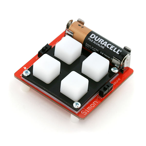
Simon - Surface Mount Soldering Kit
Replacement:KIT-09882. The new version of this kit adds extras of the small components to help you out if you misplace a super tiny resistor. It also has small corrections to the manual and better instructions.
This is a kit of loose components that go along with the SMD Soldering Lecture. This is considered an intermediate kit for people who have soldered before and wish to learn how to solder surface mount components. This kit does not include a programmer or a battery. You will need an external programmer to program the firmware onto the ATmega328. All parts are listed below.
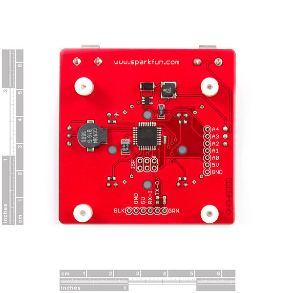
This PCB is version '0E' or zero-error. The PCB has zero errors designed into it. We offer versions with errors (2E for example) for those who enjoy troubleshooting and correcting PCB errors.
Please note that this is now shipping with the 328. This IC is pin compatable, and interchangable with the 168. You will need to modify the make file to reflect this change.
**Note: **This is an older version of the Simon SMD kit, it's since been replaced by a newer version. We found a handful of these in stock, however, so we'll be selling them for a limited time at a reduced price.
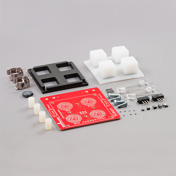
Through-hole components:
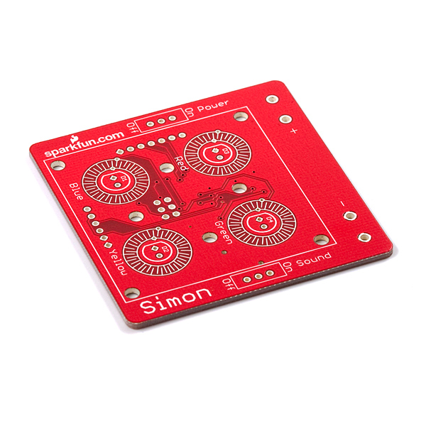
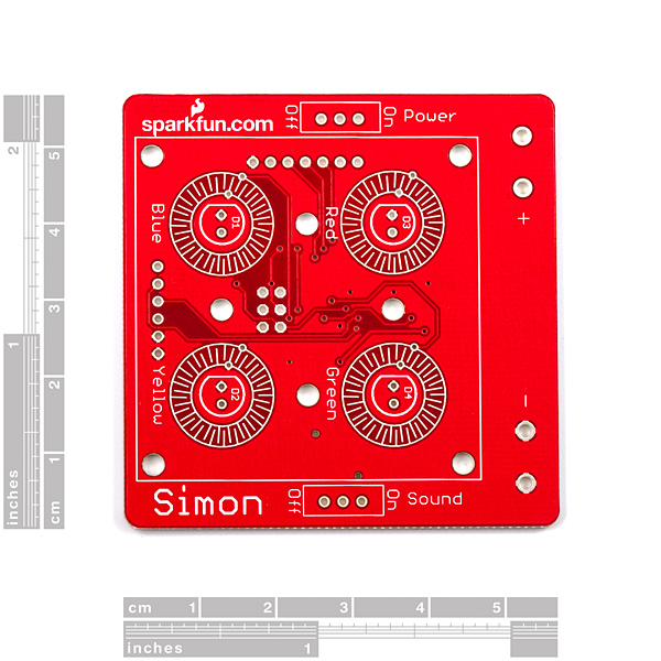
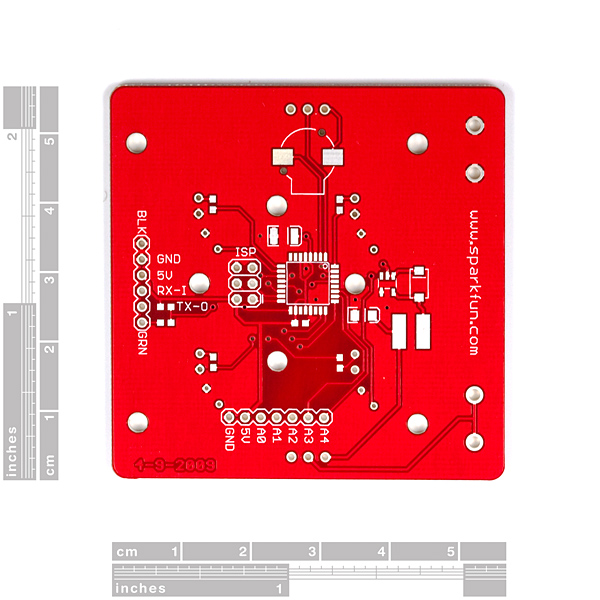
- 1 x ATmega328 based Simon PCB
- 2 x AA Battery Clips
- 2 x Slide switches
- 4 x LED (Yellow, Blue, Red, Green)
- 4 x Screws
- 4 x Plastic Standoffs
- 1 x Rubber 4-Button Pad
- 1 x Button Pad Frame
SMD components:
- 4 x 330 Ohm Resistors
- 1 x 10k Ohm Resistor
- 1 x 47uF Capacitor
- 1 x 10uF Capacitor
- 1 x 0.1uF Capacitor
- 1 x MBRA140 Diode
- 1 x 22uH Inductor
- 1 x NCP1400 SOT-23-5 IC
- 1 x ATmega168 TQFP IC
- 1 x Buzzer
- Simon Assembly Procedure (follow the steps! [5MB])
- Simon Board (component print)
- Simon Eagle Files (for trouble shooting)
- Simon Firmware (for programming)
- Simon (Old) ATmega8 Firmware (for programming)
Simon Schematic (for general reference)
Here is some good information for SMD soldering:
SMD Soldering Basics (big 4MB)
-
Be sure to checkout our Surface Mount Soldering Tutorial and our SMD soldering guide.
Simon - Surface Mount Soldering Kit Product Help and Resources
Simon Says Experiments
October 21, 2010
So you've built up a Simon Says kit? What next? This tutorial will get you up and running with Arduino software, guide you through a few example sketches, and send you on your way to create your own. Careful, this stuff is highly addictive. :)
Comments
Looking for answers to technical questions?
We welcome your comments and suggestions below. However, if you are looking for solutions to technical questions please see our Technical Assistance page.
Customer Reviews
No reviews yet.
Wow! SMD soldering is not nearly as hard as I thought! Using the AVR Programming adapter sold here made programming this thing so much easier. If you solder headers to the back, they may interfere with the button pad, I cut a small square out of the button pad where the header comes through.
By the way, I am twelve years old.
Be warned that the chip doesn't come programmed, and the common software to program this chip with is not compatible with Vista/XP x64 (PonyPreg will not even install, WinAVR needs the giveio driver which is not x64). Also, to program it you'll need to jerry-rig wires from the board to the parallel/serial programmer, or buy the $0.99 AVR adapter available here and some pins to have a less messy programming solution. A lot of headaches trying to get this thing programmed.
Assembly is pretty straight-forward. It would be nice if they included a couple extra of the little resistors and caps - I sent one flying with my tweezers and good luck finding it. Rigged a full-size resistor across that gap to make it work, but this could easily be by including an extra few cents worth of resistors.
Please warn people that this does not come programmed, and that the programming software is only x86 (32-bit) compatible.
I just finished this after 3 days of fighting with it and I hope my comments will help some people. 1- Make sure you realise that you need to program it after so make sure you have a programmer and the breakaway pins to connect to it (They don't come with the kit). I used the pocket programmer and was astonished at how little documentation came with it (what do the lights mean, what do the jumpers do?. This is key...Use B 32 NOT B 1 and call it a -patmega238p not just -p atmega328. (hope I just saved you 3 days). The button debounce fix needs to be programmed as well. I loved this kit to teach all the elemiments of embedded projects and unfortunatally if it had of worked right the first time I would not have learned as much
Is there anyway you could post instructions on debugging? This was my first SMD project and it looks like I did something wrong. I tried to do everything possible to check for shorts or disconnected pins, but everything seems good, however when I try to program it avrdude fails; my programmer works on every other project I have laying around; just not this guy (I bought and built two of them and they both have the same failure). The blue LED pulses when I run avrdude (if that helps debug). Would appreciate any help I could get in getting this working without having to try a third time. They are both 6/3/2009 boards.<br />
<br />
C:\Users\doobie>avrdude -p atmega328p -c usbtiny -B 1 flash:w:C:\Users\doobie\<br />
Desktop\simon\Simon-v21.hex -F<br />
<br />
avrdude: initialization failed, rc=-1<br />
avrdude: AVR device initialized and ready to accept instructions<br />
avrdude: Device signature = 0x000000<br />
avrdude: Yikes! Invalid device signature.<br />
avrdude: Expected signature for ATMEGA328P is 1E 95 0F<br />
<br />
avrdude done. Thank you.<br />
Just a random comment. Got the kit, LOVED it (lost a 0.1uf decoupling cap, but meh), but was reading the sticker on the sweet SparkFun box. It lists parts on the kit as still including the ATMega168, and also says it includes a battery. Now, I knew not to look for these parts as they have been upgraded to the 328 and don't include a battery, but you might want to update your stickers. But I am a very happy customer, thank you SparkFun!
The 2E version is mentioned here. Is it available through the website?
We have gone through all the error boards already. We might have more errors in the future.
This was my first experience with SMD soldering, but I thought it was fun and easy. As others have said, there are no extra parts so be careful not to loose any of the teeny tiny resistors. I had forgotten that the Atmega328 doesn't come pre-programmed with the Simon firmware, but I managed to set up my Arduino as an ISP programmer with AVRdude. I've also noticed that there doesn't appear to be any debouncing, but as long as you press the buttons quickly it's not a problem.
I'm REALLY disappointed that this kit does not come with extra parts. Every other SMD kit I have built has always come with extra parts for when you sneeze and lose a resistor or two. Without out the extra parts, it makes the build way more nerve racking and not enjoyable at all.
Besides that, it's a fun kit and good refresher. The firmware for it seems to either have no de-bouncing or poor de-bouncing. A few games were cut short by it reading two presses when there was only one.
My kit came with a 1k pullup resistor, not the 10k resistor mentioned in the hardcopy instructions (and a component that doesn't exist on the version of the circuit board in the pdf document). I realize the kit is often used in hands-on classes where there's an instructor to answer the questions, but maybe a "things we've updated" doc would help?
I also managed to mangle the 22uH conductor, and had one of the 0.1 uF capacitors disappear on my worktable after slipping off the circuit board during assembly, I'll mail customer service to see if I can get the part numbers to replace them.
Just noticed the 1K resistor IS in fact in the PDF, so that is up-to-date as the current board revision, it's just the hardcopy with the 10k. That's expected, especially when you're including nice glossy color inserts, need to use up the old ones before you print/include new ones.
The code I have from this page (as of 7/23/2010) doesn?t match the board. I?ve been working on changing the code, and I?ve the LEDs working, but I can?t seem to get the buttons working. Is there a newer version of the code?
Can you be more specific about what's going wrong? I might have run into the same issue as you have. In my case, when I first compiled/loaded the firmware, the atmega238 would reset every 1/3 second; so, it didn't initially seem like the buttons would work.
Version that shipped from an order on Jan 14th came with an ATMega328 like the preassembled SMT ones do. Nice bonus.
However, the firmware's makefile still has it set to ATMega168. This is FINE, you can build the hex for 168 and upload to a 328 without any issues. BUT, if you're planning to hack this and make use of the 328's beefier specs (extra 16K of program space, 1K of RAM(which is really the point), prepare to do some work as the existing code doesn't simply drop-in after rebuilding for the bigger device.
Where can I find replacements for some of the SMDs in this project? In particular the 22uH inductor. I had an accident with it and need a replacement. Thanks!
ok.. Here is what i found: The layout of the board changed. The video tutorial one is a really outdated one and the one the instructions followed was still different. There is no mention for the 10k resistor which goes next to the TX. The pin headers you have to come up with yourself, i had some to spare. The programming was actually really easy, I have an STK500 I have no clue how to use yet.. yet i managed.. im so happy about that. Nice project.. im SMDfied!
This is a great kit for practicing SMT soldering. I was fortunate enough to be able to assemble one of these at this year's Maker Faire. This is the first time I've ever soldered something with this many SMT components, and all went well.
Much thanks goes to SparkFun for hosting the classes at the Faire and graciously donating the boards (proceeds went to charity!) Thanks also to the infinitely patient SparkFun staff for their soldering knowledge and moral support!
Hi Sparkfun, I put this kit together during your SMD workshop at the Maker Faire and wanted to say a big thank you for setting that up. Great workshop, and a great way to get your brand known at the maker faire; I'll certainly be looking to buy parts from you in the future.
One question on the board though, what kind of programmer works with this board? I've taken a look through your catalog and have come away confused. It wasn't obvious which ones would fit the 6 pin 'ISP' connector on this board. Any chance you can update the product description with a link to suitable programmers? Thanks!
neilp, you should be able to use any standard AVR programmer that supports the ATmega168, e.g:
AVR Development Tools
You might need a 10-pin to 6-pin adapter, e.g. one of these two items:
AVR Programming Adapter
AVR - ICSP Adapter
I was able to reprogram it using an AVR Dragon board, using avrdude. However, using the default avrdude settings gives me a "Yikes! invalid device signature" error. I found that adding '-B 20' to the avrdude command line allowed it to program correctly.
One note, the board I have from Maker Faire is dated 6-25-08, and the source code example here doesn't work on this board without changes, as the LED outputs are on different pins. This page has an example that seems to work for the 6-25-08 board:
Lecture 7 - SMD Soldering
Since the updated 0E version of the board doesn't match the older 'SMD soldering lecture' a bit of warning would have been nice with the link to this kit from the lecture. Especially some notice about 2x3 ISP (with no header in the kit) versus the 2x5 of the 2E version.
The 0E version comes with the Atmega168 but the firmware available is for the ATmega8. Can you release an update or give some tips on what to do to update the firmware? I'm ready to test my soldering skillz!