- Home
- Product Categories
- Distance
- Ultrasonic Range Finder - LV-MaxSonar-EZ3

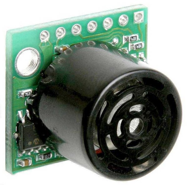
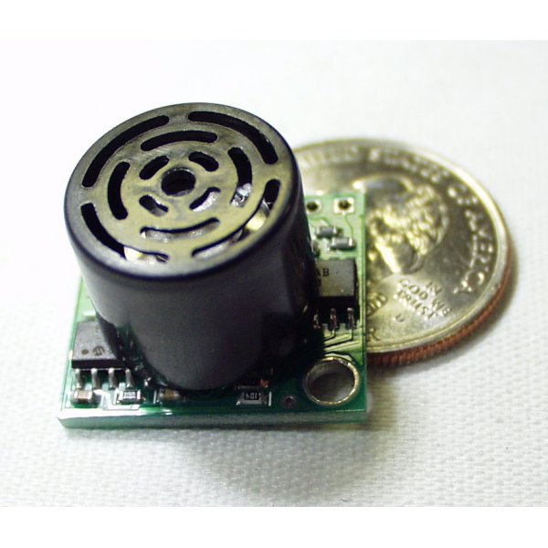
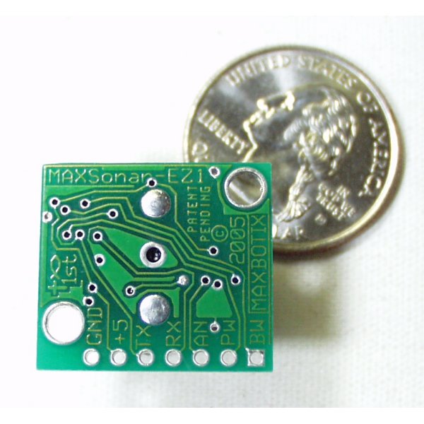
Ultrasonic Range Finder - LV-MaxSonar-EZ3
This is the fantastically easy to use sensor from Maxbotix. We are extremely pleased with the size, quality, and ease of use of this little range finder. The serial interface is a bit odd (it's RS232 instead of standard TTL), but the PWM and Analog interfaces will allow any micro to listen easily enough. The sensor provides very accurate readings of 0 to 255 inches (0 to 6.45m) in 1 inch increments with little or no dead zone!
Maxbotix is offering the EZ0, EZ1, EZ2, EZ3, and EZ4 with progressively narrower beam angles allowing the sensor to match the application. Please see beam width explanation below.
Control up to 10 sensors with only two pins! Checkout the Maxbotix EZ1 FAQ listed below.
- 42kHz Ultrasonic sensor
- Operates from 2.5-5.5V
- Low 2mA supply current
- 20Hz reading rate
- RS232 Serial Output - 9600bps
- Analog Output - 10mV/inch
- PWM Output - 147uS/inch
- Small, light weight module
- Datasheet
- Beam Width Explanation
- Maxbotix EZ1 FAQ
-
Checkout Mikey Sklar's flame-based trampoline, the high-lighter, using the EZ1!
Ultrasonic Range Finder - LV-MaxSonar-EZ3 Product Help and Resources
Photon Remote Water Level Sensor
June 2, 2016
Learn how to build a remote water level sensor for a water storage tank and how to automate a pump based off the readings!
"RS232" Output or Inverted TTL
If the ultrasonic range finder indicates that it has an "RS232 Serial Output" and is outputting an inverting signal with the voltage level based on Vcc, you could just use an inverting circuit using a transistor to invert the signal. This is not a standard RS232 that uses +/-12V. There are a few methods of flipping this signal through hardware or software. The resources and going further will provide specific examples.
Inverting Signal w/ Hardware
Doing a quick test using a retired NPN transistor from our storefront, I was able to get it working based on the circuit using a RedBoard Programmed with Arduino. I was using an Arduino so Vcc in my circuit was 5V. Since it's basically two diodes within the transistor, you will want to use resistors to limit the current. I just used two 330Ohm resistors just like I was turning on an LED. You probably do not need to do this but the values might need to be adjusted when using it at higher speeds or if the transistor is not fully turning ON/OFF. Testing with a multimeter, it worked as expected. An input of 5V would result in 0V (logic LOW) on the output since the transistor was turning on. With an input of 0V, the transistor would not be conducting so the output would be held HIGH at 5V. Using an Arduino serial passthrough for further testing, I was able to view the ultrasonic sensor's output data without any problems.
"RS232" Output and Inverting w/ Software
Otherwise, you could be clever in writing your code to store the value and possibly apply some sort of logical NOT operation. In Arduino, there is a special feature using software serial that inverts the signal by setting a parameter to true [ "Software Serial Constructor" – https://www.arduino.cc/en/Reference/SoftwareSerialConstructor ]. There was someone in the Arduino forums that provided example code to invert the output, parse the data, and output it through the serial monitor here => [ User "Goldthing" - http://forum.arduino.cc/index.php?topic=114808.msg864009#msg864009 ].
Connecting Ultrasonic Sensor to Raspberry Pi
There is a tutorial from MaxBotix that shows you how to connect ultrasonic sensors to Raspberry Pis => [ http://www.maxbotix.com/Raspberry-Pi-with-Ultrasonic-Sensors-144/ ]. Certain ultrasonic sensors listed in the article require an inverter. If the ultrasonic range finder's output serial output is " RS232 " like the sensors listed under "Ultrasonic Sensors that Require an Inverter" , this indicates that the signal is basically an inverted output with the voltage level based on Vcc.
Therefore, you would need to follow the tutorial and use a serial inverter in order to use it with the Raspberry Pi. If you are using a Raspberry Pi a transistor, Vcc should be 3.3V since the Pi uses a 3.3V system.
Resources and Going Further
Core Skill: Soldering
This skill defines how difficult the soldering is on a particular product. It might be a couple simple solder joints, or require special reflow tools.
Skill Level: Noob - Some basic soldering is required, but it is limited to a just a few pins, basic through-hole soldering, and couple (if any) polarized components. A basic soldering iron is all you should need.
See all skill levels
Core Skill: Programming
If a board needs code or communicates somehow, you're going to need to know how to program or interface with it. The programming skill is all about communication and code.
Skill Level: Rookie - You will need a better fundamental understand of what code is, and how it works. You will be using beginner-level software and development tools like Arduino. You will be dealing directly with code, but numerous examples and libraries are available. Sensors or shields will communicate with serial or TTL.
See all skill levels
Core Skill: Electrical Prototyping
If it requires power, you need to know how much, what all the pins do, and how to hook it up. You may need to reference datasheets, schematics, and know the ins and outs of electronics.
Skill Level: Competent - You will be required to reference a datasheet or schematic to know how to use a component. Your knowledge of a datasheet will only require basic features like power requirements, pinouts, or communications type. Also, you may need a power supply that?s greater than 12V or more than 1A worth of current.
See all skill levels
Comments
Looking for answers to technical questions?
We welcome your comments and suggestions below. However, if you are looking for solutions to technical questions please see our Technical Assistance page.
Customer Reviews
4 out of 5
Based on 2 ratings:
Great Unit
I am using it to trigger a Halloween prop and it works great at the distance I want it to trigger.
Works very well
I replaced an SR04 ultrasonic sensor with this so I could get better accuracy, distance, and a narrower beam width. Works great.
The beam-width explanation link is not an explanation. It looks like an advertisement.
i'm choosing based on beam width (i used an EZ-1, which worked just great, but foudn the beam wider than i wanted) and puzzled out the datasheet (which is dense, but complete).
the key is the diagram at the bottom lower right of the first page.
there's a paragraph that ought to be there, they assume you know that: sonar (sound) has to reflect off the thing you want it to "see" and, intuitively, if the thing is very thin it is hard to see at a distance.
the four diagrams show the result of "seeing" the target (A, B, C, D) described. A, the 1/4" rod -- very thin!! -- can be seen out to about 4 feet (at 5V). It can see it not only when pointed directly at it, but when the thing is up to approx. 1 foot to either side of straight ahead. The implication is that beyond 4 feet, it cannot see something that thin. this is entirely reasonable, and excellent performance.
For D, the 11" wide board, the EZ can see it up to 20 feet.
They imply -- and i can verify -- that their test of side-to-side beam width applies also to up-and-down, in other words, the beam is more or less like a... q-tip? propane torch flame? the beam pattern is a 3-dimensional space, hard to represent on paper.
its a great product. I'm using PWM and interrupts on the trailing edge and getting very good haptic feedback from an EZ-1. I will buy the EZ-3 for the narrower beam.
Cross-posting this to the EZ-1 comments because that part seems more popular.
I have an EZ3 and have found it's not very good at detecting people. As you can read on the Maxbiotics website (at http://www.maxbotix.com/articles/037.htm):
People detection generally falls between grid pattern A and grid pattern B when the sensor is perpendicular to the person. Typically a person will reflect the same amount of ultrasonic energy as a 1 inch diameter dowel. Even though people are physically large targets, humans are a soft target that absorb a large amount of ultrasonic sound and reflect only a fraction of the ultrasonic sound.
$27.95 !?!?
Similar sensors are available for 1/10 the price on Ebay.
Will this sensor change when something moves on the other side of glass?
About a year too late, but, no. The sound waves will just bounce off the glass.
Is this sensor dust proof?