- Home
- Product Categories
- 7-Segment
- 7-Segment Display - 6.5" (Red)

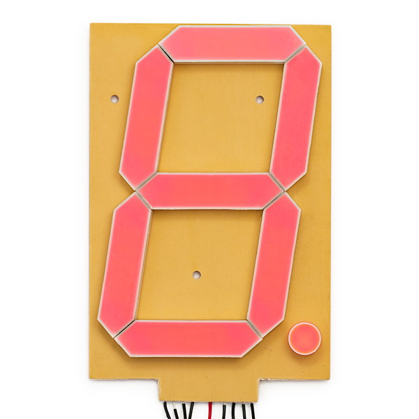
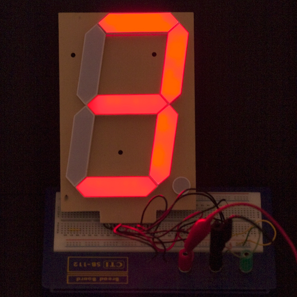
No really - it's 6 inches (153mm) tall! This very large 7-segment display can be seen from a hundred feet away. So many projects to try, so little time...
As dictated by the display datasheet, each segment must be limited to 20mA. To use this display you will need a 12V supply and current limiting resistors on each segment. Your power supply should be rated for a minimum of 160mA for each digit in your overall display. For example, a 4 digit display will work nicely with a 12V/1A supply.
7-Segment Display - 6.5" (Red) Product Help and Resources
Large Digit Driver Hookup Guide
June 25, 2015
Getting started guide for the Large Digit display driver board. This tutorial explains how to solder the module (backpack) onto the back of the large 7-segment LED display and run example code from an Arduino.
Core Skill: Electrical Prototyping
If it requires power, you need to know how much, what all the pins do, and how to hook it up. You may need to reference datasheets, schematics, and know the ins and outs of electronics.
Skill Level: Competent - You will be required to reference a datasheet or schematic to know how to use a component. Your knowledge of a datasheet will only require basic features like power requirements, pinouts, or communications type. Also, you may need a power supply that?s greater than 12V or more than 1A worth of current.
See all skill levels
Comments
Looking for answers to technical questions?
We welcome your comments and suggestions below. However, if you are looking for solutions to technical questions please see our Technical Assistance page.
Customer Reviews
4.5 out of 5
Based on 22 ratings:
1 of 1 found this helpful:
The look Great BUT!
Three out of the four that i ordered arrived with several of the segments soldered in backwards. I spent many hours chasing my butt trying to figure out why my code was not working. Come to find out (as i said) several of them had segments in wrong. Other than this issue, so far i like the way they look.
Sorry to hear this. Please contact our support team and we'll be happy to help you.
1 of 1 found this helpful:
Visible at least 100 feet away!
I love using these for a scoreboard system for outdoor tailgating and corn-hole games, but usable for any highly visible and bright user-interface. Get (2) per scoreboard, or get (4) and make a huge clock!
Always get the backpack module for each digit, to reduce your wiring needs and complexity of pins, and allow simple daisy chaining of each item.
PRO TIPS: A large solder and attachment area, so 1) Wipe a bit of Rosin Soldering Flux on all mating surfaces, 2) Dab a solder bead onto each connecting pin for the display and backpack, 3) Align both pieces together, and fuse melt and feed a little more solder to bridge the gap while its molten. SOLID!
Nothing else out there like these babies!
1 of 1 found this helpful:
Easy to work with....
Having no experience with 7 segments before I found these are very easy to work with as long as you get the SparkFun Large Digit Driver that goes with it up above. Very bright, changes numbers nicely, good instructions with the driver hookup, and durable product.
I would buy again. Only suggestion is to add more color options.
2 of 2 found this helpful:
Not Suitable for Outdoor
Although these things work very well for my application, an outdoor radar speed sign, they are failing on a regular basis. I have them mounted in a plastic weather tight enclosure which is reset into a larger enclosure. In the cooler temperatures in the Northwest, they lasted 7 months. In the hotter temperatures here in So. Calif. (around 90 F) they fail within weeks. I'm not impressed.
2 of 2 found this helpful:
temperature sensitivity
Where those are really good for indoor, they suffer from heat. I got them on the outside running stadium since spring. First hotter day killed them without warning. Was debugging that whole Christmas, and indeed, its the leds are what went bad. Maybe inside the beautiful box the temperatures goes over all thresholds.
Dear sparkfun, I really value your products, do you mind to enhance description of this product, clearly stating it is indoor - room temperatures only? or ideally, add exact temperatures this can work in?
We will try to get temperature data from the manufacturer and will update the product page once we have that.
2 of 2 found this helpful:
So far so good.
I ordered 4 of these to make a large timer and so far they are working great. I wish they were a bit brighter in terms of light, and a bit less pink-ish in color though!
1 of 1 found this helpful:
RED LED Large
The product is good. So far it worked for what I wanted to do. The segments are bright I will buy more shortly.
Best large 7-Segment Digit ever bought
Very bright, easy to mount, good quality. Perfect for me in conjunction with the SparkFun Large Display Driver. I coverd my 4 digit display with red acryl-glass. Even on sunny days you can read the digits from a hundred feet away.
Bright, clean
Very good - bright, responsive. I'll order more.
Work great!
I have used a bunch of these and when used with the 7-Seg LED Driver board that Sparkfun offers, getting it up and running was a breeze.
Perfect for my project!
Was pleasantly surprised when I saw that it was 12VDC. Now I don't need to step down the voltage on my project.
Very Good
It would be better if the background were black https://www.youtube.com/watch?v=ABtPiHLFrAk
Fun little Item, slight quality issues
I enjoyed working with these components. Paired with the driver port that Sparkfun offers they are very easy to control. My only reservation is that I ordered six of these and two of them had issues with their decimal. On one the resistor for the decimal was soldered on poorly to where the solder bypassed the resistor making brighter than the segments. The other didn't work because the solder wasn't properly joining the resistor to the circuit. Thankfully I needed to remove all the decimals for my project.
Perfect product
I like them a lot, you should offer in blue, white and yellow It will be a best seller
Large display with even brightness
I was looking for large display and this suited just fine for my project. The brightness is uniform and is visible from a far.
Progress with Large 7-segment display
I ordered and received four of the large 7 segment displays with their associated drivers. I soldered the driver boards to the back of each. I then discovered that I should have applied some insulating tape to the rear of the display drivers before soldering them to the back of the display boards. I was disappointed to learn this after soldering. I tried a couple of methods of inserting insulating material in between the driver boards and the displays. I was not successful.
Fortunately my boards do work properly without the insulation. Due to twisting when mounted they may fail.
I was able to modify the example sketch to display a fixed value from an ESP 32 Dev board. I was then able to modify the sketch to receive data via ESP NOW from another ESP 32 Dev board.
My ultimate goal is that the large displays will act as a remote display for a Batcher project that I made with another ESP 32 connected to a flow meter. The Batcher will show a running total on its own display and also transmit this value to the other ESP 32 and the large digit displays. This will allow me to view the running total from either display. This is used to mix "Batches" of spray mixture for use on my farm crops.
I haven't decided on an enclosure for the four large displays. Maybe some type of picture frame could be modified for this.
Good quality,quick shipment!
This 4th on my list
Beside owning two 2 dogs and a kitten, this is the #4 Best. Excellent product and super great docs you supplied.
Great display
This display is great. Very visible. I've used a couple of them for an educational counting board for my sons and they love it.
I have your (big) number...
These are hilariously large and once you get them solidly connected to the driver boards, they're easy to use. I found the connection to the driver boards needed soldering to really be reliable, but what else is new?
Decently bright, and now I just have to figure out what I'm going to do with them...
0 of 1 found this helpful:
Works great
Bought six of these to make a giant clock for the back of a large meeting room. Speakers now have no trouble telling what time it is.
One segment on one of the digits was not soldered on one end, but it took longer to warm up my iron than it did to fix that.
Certificate of Origin is required for customs clearance. Please send me a certificate of origin by e-mail. My order number is # 5904836. ASAP.
Good Product :) https://www.youtube.com/watch?v=ABtPiHLFrAk
I made a 3d model of this in Fusion 360, here is the file. Due to manufacturing variance, I would double check against the examples you receive before you manufacture any mounts for them. I omitted the decimal and mounting holes since they I did not use them in my mounting solution. I also just blocked out the volume of the Sparkfun Large Digit Driver since I did not need that much detail for my application.
https://fusion360.autodesk.com/projects/7-segment-display-6-5-red
The code I used is here for a countdown clock for a robotics competition. https://github.com/battlebotsrob/MASSdestruction-arena-controller-
This product listing is very poor; tons of details are missing. Let me try to fill in the blanks. I'll also make a few notes about problems I found with the product. I'm sure those notes will make me sound a bit negative, but it's really no big thing; the displays work great despite their rough edges and it's easy to make a fun project with them.
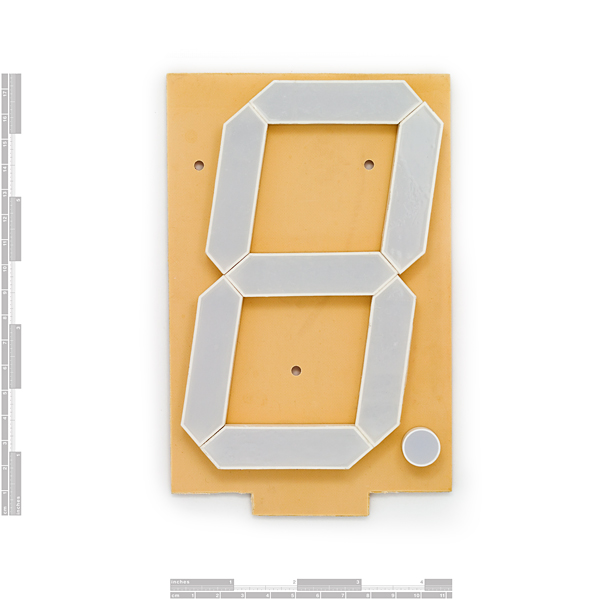
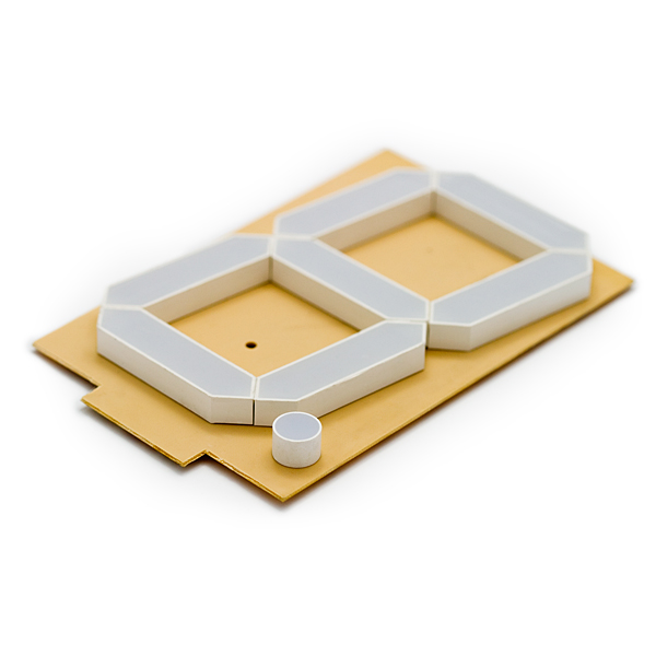
First, they're not 6.5 inches high. The PC board is almost 6.5 inches tip-to-tip, but the actual display is about 6 inches high. The tolerances of assembly are incredibly poor. The data sheet says that the listed dimensions are within .2 millimeters. I bought 13 displays, and received them all with the same manufacture date. They varied in size by more than 3 millimeters, and the position of the display on the board -- and relative to the mounting holes -- varied as well. This made mounting the displays in a straight line pretty touchy. Further, some of the individual segments weren't mounted flush to the board and visibly angled.
A #6 screw fits fine in the mounting holes. M3.5 should work, too, but that's not what I actually used. There are three holes for screws. Two are 1.5 inches from the top of the board, and the other is two inches from the bottom main edge (not the card edge) of the board.
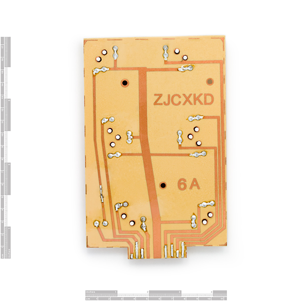
There's no hope of using any kind of edge card connector as the card finger is not a standard width and the traces are irregularly sized and spaced. The product would be vastly improved if the displays had any landings for through-hole connectors, either single- or double-in-line, so terminating a ribbon cable to a header or even just soldering wires would be easy.
The forward voltage of each segment really is 12 volts. The decimal point has fewer LEDs, and it turns out there is a tiny SMD resistor on the display's foil side to limit current for that segment. It is almost comparable to the rest of the segments, but the intensity isn't exactly identical.
If you drive the displays with a 12-volt source, you'll probably be OK with duty cycle. At continuous current, you'll want a 110-ohm current limiting resistor. Or, you can use a constant current source--perhaps one is built in to your controller board.
I hope that helps!
So, I got it modded. The segments are removable. Each segment has four pins, although I am unclear on the spacing. I superglued the segments together, traced and cut out the digit in black foam board and hot glued it in place. I was wiring it up as a common cathode when I realized I was out of solder...
http://i58.tinypic.com/2zhihyx.jpg
http://i57.tinypic.com/rl94t1.jpg
http://i58.tinypic.com/rivqmp.jpg
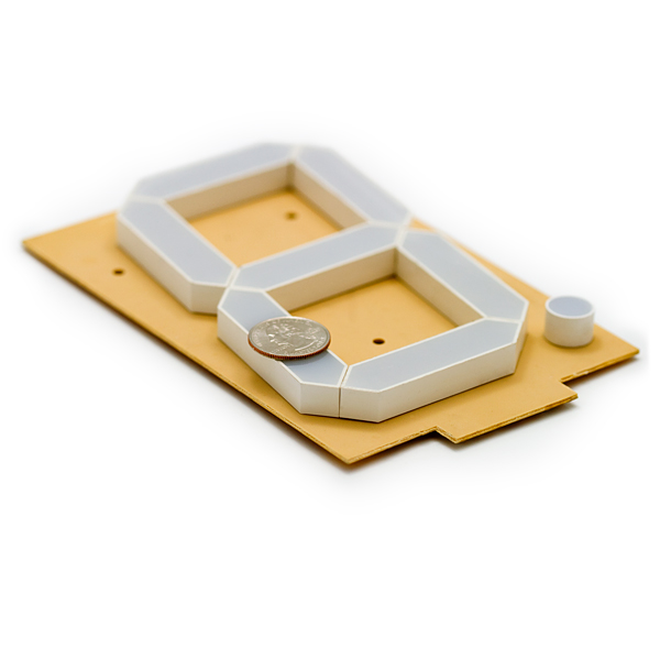
Thanks for the pics! They helped me decide not to buy this product. I thought the plastic was attached to the board and the LEDs were grown on the PCB, as in COBs. But your first photo shows every segment is epoxy encapsulated, so no use to me. I was going to use my own ultra-high intensity traffic-light green SMT LEDs, but this changes it all. Thanks again!
Here's an Arduino project that uses these large digits with high(er) current sink shift registers: tpic6a596
http://truepathtechnologies.com/blogs/?p=336
The board (that's made) can be used as a general purpose 1-4 Digit display driver for these large digits!
The quality of these displays is very marginal. They work and they light up, that's fine. I ordered 13 count at the end of 2010 and they were delivered as shown in the pictures here -- with a beige PC board and red segments.
I ordered 13 more to make another instance of the same project in May of 2011. I received 12 boards which were black, but had the faces poorly painted white. The 13th board was black without any white paint.
Most of the vertical segments look like they have been exposed to too much heat because the lens plastic is wavy and rippled.
These are hugely popular -- everybody loves big, bright displays. I hope SparkFun can put some pressure on its supplier to get the quality control together. There's just too much variance.
Now the datasheet says that it's forward voltage is normally 12 volts. Does that mean if I have a 12 volt supply I need no extra resistors to power it?
You'll still need a current limiting resistor or current source. The LM317 makes an excellent current source and is more precise than using a resistor. You should probably have >14V available.
can anyone recommend a shift register to use with these? the one that was used in the deleteaso tutorial is no longer a stocked item anywhere i can find.
I bought a handful of these about a month ago and really like them. I spent a lot of time figuring out how to get them hooked up to my Arduino, and I have posted everything on my blog. I hope this helps get someone up and running quickly. http://deleteaso.com/2-sparkfun%E2%80%99s-7-segment-red-65%E2%80%B3-display-and-arduino/
Sparkfun -- please PLEASE consider tweaking this to work as an I2C display....
I just bought one to experiment with. And by experiment, I mean mod to get rid of the crappy PCB. I sure hope the segments can be desoldered. It looks like they can, judging from the rear pic of the PCB, but I cannot tell if they glued the segments in place.
I need three of these for a project, and looks will count. The quality of assembly on these looks pitiful, but it is the largest I can find.
It arrived yesterday. I haven't had time to mess with it, but it looks like it should be easy to get the segments off of the board. The quality is not as bad as I was expecting, but there are minor quality issues.
Good luck! Let us know how it goes.
I'm an Arduino beginner and more of a software type so please forgive me but... I don't understand why you would need a current limit resistor when powering one of these with 12VDC. The datasheet shows that the 12volt drop will effectively occur over 6 LEDs. That means 2volts per LED. What am I missing here?
EDIT: Nevermind, I understand now.
I created a digital clock with these displays. I made a BackPack PCB that uses the TPIC6A595's so you can daisy chain them. A link to a video demo is on my page here... http://damage-designs.com/blog/2011/5/28/arduino-based-large-digital-clock-with-7-segment-display.html
The PCB files themselves are up on OSHPark.... http://oshpark.com/profiles/Damage
Enjoy.
I'm an arduino beginner and am struggling to get even one segment to light. Can somebody provide a very simple way to light up even one segment with an arduino uno?
I have three of these segments with three TPIC6B595. Somebody mentioned using capacitors, I know resisters need to be used. A much simpler tutorial would be awesome. What size capacitor? How to wire it? What size resistors?
Thanks!
try using circuito.io , choose in the output bar the seven segment
You need greater than 12 volts to get it to light. I'm using nominal 14.8V (max 16.8V) Lithium Ion battery. Connect supply(+) to 5 (middle) trace of display. Connect any one of the other display segment traces to a current limit resistor. Connect the other side of the current limit resistor to supply(-). Segment will light. Resistor should be picked to set up around 20mA current. Forward voltage for display is around 11.6V. For my battery this gives (16.8 - 11.6) = 5.2V / 0.020A = 260ohms. When you are ready to hook up the TPIC6B595, break the resistor's connection to ground and connect it to one of the drain pins on the TPIC6B595 (this will become your segment ground when active). You of course need to have the other pins of the shift register connected correctly and you have to understand how to use it. The project I'm building has four digits and I plan to use a second TPIC6B595 connected to the first (and P channel MOSFETs and pullup resistors ) to do digit selection for multiplexing as well.
EDIT: Actually now that I think of it... it seems to me that since a red LED is typically driven at 20mA and on the 7 segments there are two parallel paths, you would want pick resistors to drive each segment at 40mA so that each parallel branch of LEDs gets 20mA. The decimal point however is a single branch of LEDs so you would want to pick a resistor that would drive that branch at 20mA. Perhaps others can comment on whether they believe that thought is correct or not.
How well can these be seen outside on a cloudy day?
hi, Iam looking for large seven segmen. its size about 8 inch per character. i need not only lamp, but completelly with its decoder, its can cange from BCD input. I will use output Digital from PLC to control it. Tengkyu verymuch
I can't buy these products in china . who can help me?好桑心哇
Here is a project I have been working on, using an Arduino with a Chronodot RTC:
http://www.youtube.com/watch?v=XdteNh2kWEM&feature=youtu.be
In the event this can help anyone. I created a corel draw template to be used for a laser cutter. http://www.stuffjimmakes.com/misc/Sparkfun-08530.cdr
How does the number get changed? is there a wireless reciever or what?
You have to provide the electronics to drive each segment of the display. They don't display anything on their own.
Here's my project as an example.
Has anyone cut off the 'slot header' at the bottom of the board? You can solder wires directly to the traces, pretty much anywhere on the board, so I really don't know why this slot is here (since it's non-standard). Just want to make sure that I'm not going to impact a sub-layer of the PCB if I pull out my hacksaw and chop it off.
Initial impression of the display: I wish they were a little brighter. In directly sunlight they may be difficult to see. Also, the three mounting holes seem very oddly placed; I would prefer them to be in the corners. And for the slot to not exist. Also, it would be nice if the datasheet actually reflected what was on the board - as another reviewer noted, there's an SMD resistor on the DP trace. I did my own calculations for a resistor based on the datasheet and now find that I have to re-do that.
I LIKE the product, would buy again, but really wish it was better.
I am making a large clock out of these. I made up a backpack PCB to go along with these make these easier to hook up. See my video on youtube here http://youtu.be/cu5GeNlZhPY for a test I did with these.
These guys are indeed pretty cool. I have to agree with the assessment on quality though. I ordered three of of these and one had all of the vertical segments installed with reverse polarity. Not a big deal, but keep that in mind if you have trouble. Use the high power shift register http://www.sparkfun.com/products/734 and you won't have a problem
Here is a shifter breakout board that can drive these displays easily http://proto-pic.co.uk/products/Shifter-kit-v1.1.html
There is example arduino code and simple library files too.
As of 10/19/2012, Proto-pic / RelChron Limited are no longer shipping to the USA. This is from an e-mail I received today when I attempted to order (5) more of their Shifter Kits mentioned above. Bummer! Caught me in mid-build of a project! Nice boards, just …
Hi There Ah, right. We don’t ship to the US anymore im afraid – too many things going missing in the post service.
Best Regards
Richard Winton Director RelChron Limited Unit 17, Kirkcaldy Enterprise Centre Myregormie Place Mitchelston Ind Est Kirkcaldy Fife KY1 3PF Reg No. SC298119 Direct : 01592 572091 Email: richard@relchron.com Web: www.relchron.com www.proto-pic.co.uk
Just gonna say - these are pretty awesome. It would be nice if they were common cathode instead of node, as that makes them difficult to control, especially if you are trying to control several of them (I used 4). What I ended up doing was chaining 4 shift registers together (ignoring the first pin, I had no use for the colon), and then running each shift register output through a ULN2003A transistor bank(is it a bank?), and then that was wired with each pin outputting a corresponding ground. the gnd pin on the ULN2003A was grounded, and the free-wheeling diodes was left alone. They all just shared a 12v power supply.
Do the individual elements have any manufacturer or part numbers on them? I can see some advantage in putting together my own modules from parts. Could make a useful clock/thermometer for my half blind mum.
No, there are no part numbers visible on the segment bars.
"krh2o | October 12, 2009 at 10:02 PM
How easy would it be to open up the display and put in higher
power LEDs?"
"Mike | December 23, 2010 at 3:24 PM
A: Impossible. "
Still true? Anyone tried it yet? This would be a great display if it could be modded for outdoor/sunlight use.
Yes, still true. The board hasn't changed to a modular design, and the segment bars are still brittle, and they're still sealed with epoxy.
I make a gigant clock with the module BOB-00099 and four of this :D
How about with six of them?
Thanks for the write-up, Mike. Despite the mounting holes not being consistently spaced from one board to the next, it looks like there might be enough room to drill an extra couple of holes if needed.
can anyone recommend a shift register to use with these? the one that was used in the deleteaso tutorial is no longer a stocked item anywhere i can find.
I'm using TPIC6B595 chips with my display.
There's code to drive them with a Propeller chip in the project thread.
bump
I used some controllers from itsdisplays.com and my project is going well.
I was looking for a better driver chip. i was hoping to use an arduino or propellor to control these things.
I was wondering if this could be offered in a color other than red?
do you think these could be de-soldered. For two reasons.
1. mount to a different PCB, and
2. Connect in common kathode configuration
Probably not easily. You would need your own PCB made probably.
The segments appear to be symmetrical. They also look like they could easily be desoldered but I have not tried myself. I think you could desolder each one individually, flip each 180 in place and resolder and probably convert it to common cathode that way.
I realized that there are three mounting holes for the display. Does anyone know what the typical screw size you would use with this display?
Maybe a #6 or #8?
I used four of these to make a data display on the back of our 2008 FIRST robotics competition robot. It was really cool... helped a lot with quick debug, sensor testing, last minute checks before a match.
I wish I could post a photo with this... but I'll just post links I guess. Display off but on the painted robot: http://www.chiefdelphi.com/media/photos/31348 Display on but on the robot before it was painted: http://www.youtube.com/watch?v=LRUsb2Pls4M
I wish they were a little brighter, but you can fix that problem by shading the display a little and putting a good red theater gel over it.
Great product! I'm thinking about buying four more for a display on a pullin' tractor I'm making controls for...
This is an awsomely huge 7 segment display. My only gripe is that doesn't have an easy way to solder a connector or header to it and it can be a little hard read read in bright light environments. Other than that it worked great for my application and saved me from having to fabricate my own huge display.
How easy would it be to open up the display and put in higher power LEDs?
Easy!
Impossible.