- Home
- SparkFun Serial DB9 Breakout

SparkFun Serial DB9 Breakout
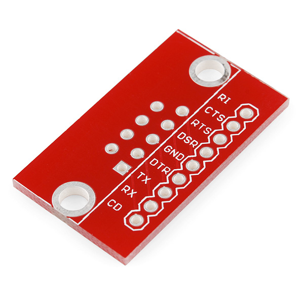
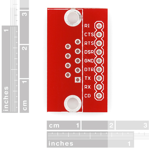
A very simple breakout board for the DB9 connector. Takes the 9 incoming signals and puts them into a breadboard friendly single row of 0.1" pins.
Bare PCB only. Please see related items for DB9 connector and pins.
- Schematic
- Eagle Files
- GitHub (Design Files)
SparkFun Serial DB9 Breakout Product Help and Resources
Core Skill: Soldering
This skill defines how difficult the soldering is on a particular product. It might be a couple simple solder joints, or require special reflow tools.
Skill Level: Noob - Some basic soldering is required, but it is limited to a just a few pins, basic through-hole soldering, and couple (if any) polarized components. A basic soldering iron is all you should need.
See all skill levels
Comments
Looking for answers to technical questions?
We welcome your comments and suggestions below. However, if you are looking for solutions to technical questions please see our Technical Assistance page.
Customer Reviews
4 out of 5
Based on 1 ratings:
Exactly as advertised.
It's a good breakout board. I'd like the through holes for the actual DB9 to be significantly oversized so that you could mount a standard DB9 to it directly.
As it is, I had to solder wires to the DB9's wire pots and then solder the wires to the breakout board. If the holes were oversized, I could have cut out the middleman and just wired the female DB9 to it directly.
This is niether Male nor Female dependant. I spent two days tracking down an issue and it turned out that I had the signals going to the wrong pins. Well, wasn't a problem with the breakout board. I placed a female DB9 on the wrong side of the board.
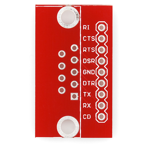
If you have a DB9F the place it on the same side as the silkscreening. If you have a DB9M then place it on the other side. This will place the silk screening on the correct header pins.
I have several of these boards, populated with both M & F connectors. The only annoyance I've found with this breakout, is that the pinout silkscreen is on the wrong side if populated with a DB9M (DE-9 M, but let's not get into that...) and straight male headers on opposing sides. I say the wrong side, because if you stick it into a breadboard, the silkscreen is on the side you can't see!
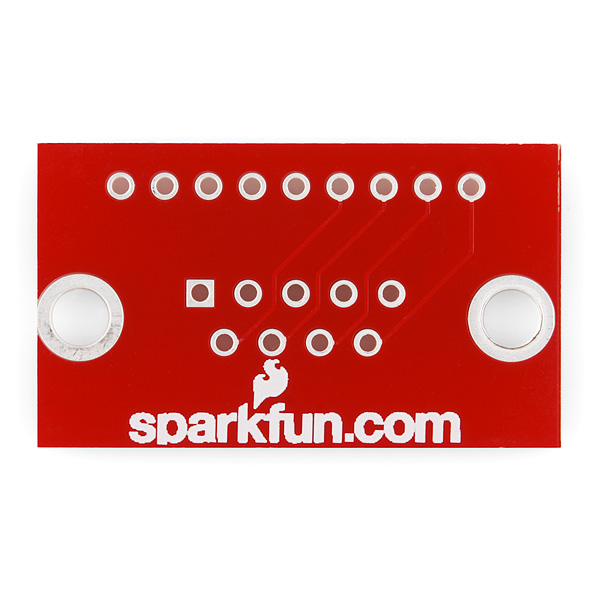
Of course, there are a couple of solutions to this; only one is satisfactory, in my view. First, you could populate with the connectors on the same side and hang it off the side of a breadboard with the power rails removed. Second, you can use 90° headers, but then the board's sticking way out of the plane of the breadboard and causing all sorts of trouble. Finally, SFE could simply add a pinout silkscreen on the other side of the board—which they're paying to have silkscreened anyway with "sparkfun.com!"
So, SFE, how about a 'non-gendered breadboard-friendly' rev. 2 breakout with pinouts printed on both sides (when your "378 in stock" run down)? Pretty please?
I think changing the name might confuse the 99.9% of us that have always referred to this as a DB9 (DB9F, DB9M, etc). Just go to Mouser and do a search for DE-9 vs DB9 and see which one helps you find the connector you are looking for. Might not be correct but its the commonly accepted term. (sorta like referring to all "facial tissue" as "Kleenex"?)
I'd love to see one of these for DB15 (vga connector)!
...There are silkscreening on both side, this is also confusing... If you have a female DB9, place it on the side where you can see the pinout for the breadboard. Or in other words; the side where there's not sparkfun logo.
We love you Sparkfun, this is clearly a breakout board for a FEMALE DB9...
SWR_DMaster is right. This is independent of connector gender. Turn the board upside down if you have a male connector.
fwiw,
male: when looking directly at the pins of the male serial cable, the GND pin is far left on the 5-pin row, and CD is far right on the 5-pin row.
female: when looking directly at the holes of the female serial cable, the GND pin is on the far right on the 5-pin row, and CD is far left on the 5-pin row.
breakout board: the square pin is CD, and at the opposite end is GND.
hopefully that'll help to avoid confusion when it's solder time. depending on the situation, it may be more useful for you to solder headers on the board to plug on female serial cable. do that with the pins' long ends on the side with the silkscreen text
Danger, Will Robinson!
This is for mating with a DE-9 "male" connector (the current version - in red - has all pin names printed, not only TX/RX).
If you solder a DE-9 "female" connector", you will have to ignore the pin descriptions on the breakout board because soldering order 1-2-3-4-5 becomes 5-4-3-2-1.
WARNING: Dead Horse Beating Ahead
After a little more research, I think it's more accurate to say that the DE-9 designation, while technically correct, is simply 'outdated'. And this is why EEs don't get invited to technicians' parties - we really don't care that they know the entire history of the D-subminiature connector series. Sorry, not interesting. "Wikipedia what? - where's that keg?"
http://www.l-com.com/content/FAQ.aspx?Type=FAQ&ID=4878
(Yeah, I know - this is why technicians have to have their own parties...)
I agree with xsk8rat. Please change the name to DE9.
"DB9" makes you guys look like newbies.
that's "DE-9", sorry
Disclaimer: I know this only because i was just served at work by one of the EE's. Using the wrong code really seemed to bother him.
It's really a "DE-9". The "DB" denotes a 25 pin size connector.
Check the standard:
http://docs-europe.origin.electrocomponents.com/webdocs/0027/0900766b80027708.pdf
And wikipedia:
http://en.wikipedia.org/wiki/DE-9_connector#DE-9_connector