- Home
- Product Categories
- PIC
- 40 Pin PIC Development Board for PIC18F4550 with USB

40 Pin PIC Development Board for PIC18F4550 with USB
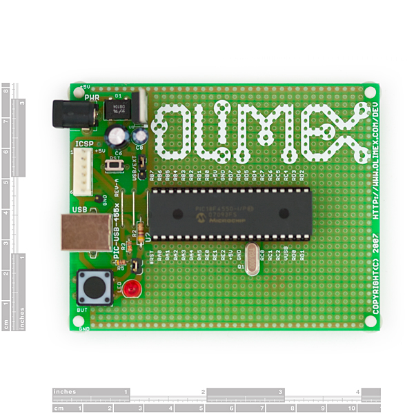
This is simple prototype board for development of USB application with PIC18F4550 microcontroller. The power of the 18F4550 is that it has USB hardware built into it so that you can program different USB stacks directly onto the IC. Microchip provides these free USB solutions for their microcontrollers which are openly available. The USB HID Class firmware can help you to build a mouse or other Human Interface Devices for Windows, USB CDC Communication class device, USB Mass Storage firmware (add your own USB disk drives to your computer), USB-to-RS232 driver. The prototyping space allows you to easily add on sensors, relays and other peripheral devices to interface to USB. The board can take power from USB or from an external supply with small jumper selection.
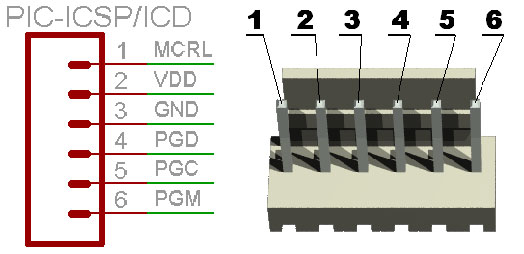
- ICSP/ICD connector for programming with PIC-MCP, PIC-MCP-USB, PIC-PG1,PIC-PG2, PIC-PG3 or PIC-PG4 and programming and debugging with PIC-ICD2, PIC-ICD2-POCKET, PIC-ICD2-TINY
- USB 2.0 type B connector allow board to be interfaced to PC host
- PIC18F4550-I/P is included
- Quartz crystal 20MHz
- LED connected to RD3 through jumper
- User button connected to RB4
- Reset button
- Power jack with diode bridge can be powered with AC or DC power supply
- 5V regulator
- Extension slot on every uC pin
- Grid 100 mils
- GND bus
- Vcc bus
- Four mounting holes 3.3 mm (0.13")
- FR-4, 1.5 mm (0.062"), green soldermask, white silkscreen component print
- 100x80 mm (3,9x3,15")
- Schematic
- User Manual
- PIC ICSP connector
- Blink LED demo code
- Button read demo code
- USB bootloader (C source and HEX)
40 Pin PIC Development Board for PIC18F4550 with USB Product Help and Resources
Core Skill: Programming
If a board needs code or communicates somehow, you're going to need to know how to program or interface with it. The programming skill is all about communication and code.
Skill Level: Competent - The toolchain for programming is a bit more complex and will examples may not be explicitly provided for you. You will be required to have a fundamental knowledge of programming and be required to provide your own code. You may need to modify existing libraries or code to work with your specific hardware. Sensor and hardware interfaces will be SPI or I2C.
See all skill levels
Core Skill: Electrical Prototyping
If it requires power, you need to know how much, what all the pins do, and how to hook it up. You may need to reference datasheets, schematics, and know the ins and outs of electronics.
Skill Level: Noob - You don't need to reference a datasheet, but you will need to know basic power requirements.
See all skill levels
Comments
Looking for answers to technical questions?
We welcome your comments and suggestions below. However, if you are looking for solutions to technical questions please see our Technical Assistance page.
Customer Reviews
4 out of 5
Based on 1 ratings:
Good PIC development board
Has on board power supply (5V). Reset button provided. I changed to PIC 18F45K50. Changed crystal to 16Mhz. I am going to replace the socket with a ZIF and use it as a programmer. I see this board is no longer available from Sparkfun. If Sparkfun is considering a new board it should have a switchable 3.3V or 5V power supply and a socket for the crystal.
When I entering bootloader mode I can see "Microchip Custom USB Device" in device manager but bootloader application like AN1310 or HID bootloader can't see my pic18f4550 (no com port for it). What is wrong? Michael.
i purchased a pic18 development board.Which Ccompiler should be used for it?Do i need to install the USB bootloader?If yes then which? I am new to this,can anyone guide please
Thank you in advance
Get the free MPLAB X IDE, with the XC8 compiler from Microchip (free versions). You will need the PICKIT3 also (~$40), but the setup is nice and very easy to use. I'm not sure about the USB bootloader, I haven't used that on this device.
I just purchased the development board and don't know how to get started. Here's what I've done so far: 1. Switch the PWR jumper pins to USB 2. Connect a USB cable to the board and PC ( I see a blinking LED) 3. Download the C source of the USB bootloader (AN1310) 4. Run the Bootloader.
Problems I'm facing: 1. With the board connected, AN1310 shows that it cannot connect to COM1. I don't know how to go about changing the port. 2. I don't know how exactly to flash a program onto the board. 3. How do I go about programming? I want the development board to function as a Mass Storage Device
Any help is greatly appreciated
I went ahead and purchased a pickit2
I recommend to upload the Pinguino bootloader. Look in google for pinguino proyect. It is an Arduino enviroment for these kind of pics. You can program the PIC via USB and use the same languague Arduino has.
Will I need to order a programmer aswell to program this? Or can it be programmed by usb by default?
Disregard
Can I order this board without the PIC? I want to use a different MCU and I don't need this 4550
Best,
Unfortunately, we can't do custom orders, so you can only this board as-is with the MCU included. However, we do have another 40pin PIC development board that comes without a MCU included, found here.
Looking at both the usbdrv.c and the boot.c files, it looks like its based from the Microchip's Bootloader App Note AN1310 (please see http://www.microchip.com/stellent/idcplg?IdcService=SS_GET_PAGE&nodeId=1824&appnote=en546974) for High-Speed Bootloader for PIC16 and PIC18 Devices.
For the Host PC app, here is the URL http://ww1.microchip.com/downloads/en/AppNotes/Serial%20Bootloader%20AN1310%20v1.03.exe
I hope this helps
Is there a tutorial for the USB Bootloader? I looked through the C source linked above, but no documentation is provided.