- Home
- Product Categories
- RFID Readers
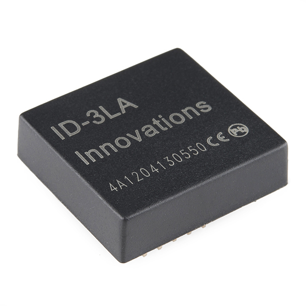
- RFID Reader ID-3LA (125 kHz)

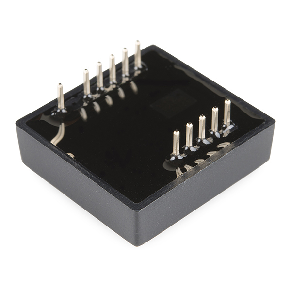
RFID (radio-frequency identification) is the wireless non-contact use of radio-frequency electromagnetic fields, for the purposes of identifying and tracking tags attached to objects. This is the ID-3LA, a very simple to use RFID reader module from ID Innovations. The only holdups are the 2mm pin spacing and you will need an external antenna. Power the module, hold up a 125kHz card, and get a serial string output containing the unique ID of the card.
Note: The new ID-3LA is essentially the same as the ID-2, but has a lower voltage input.
- 2.8~5V supply
- 125kHz read frequency
- EM4001 64-bit RFID tag compatible
- 9600bps TTL and RS232 output
- Magnetic stripe emulation output
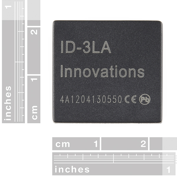
- 19x21mm
RFID Reader ID-3LA (125 kHz) Product Help and Resources
SparkFun RFID Starter Kit Hookup Guide
May 5, 2015
Learn the basics of how to get started with the SparkFun RFID Starter Kit.
SparkFun Qwiic RFID-IDXXLA Hookup Guide
March 14, 2019
The Qwiic RFID ID-XXLA is an I2C solution that pairs with the ID-LA modules: ID-3LA, the ID-12LA, or the ID-20LA, and utilizes 125kHz RFID chips. Let's take a look at the hardware used for this tutorial.
Core Skill: Programming
If a board needs code or communicates somehow, you're going to need to know how to program or interface with it. The programming skill is all about communication and code.
Skill Level: Rookie - You will need a better fundamental understand of what code is, and how it works. You will be using beginner-level software and development tools like Arduino. You will be dealing directly with code, but numerous examples and libraries are available. Sensors or shields will communicate with serial or TTL.
See all skill levels
Core Skill: Electrical Prototyping
If it requires power, you need to know how much, what all the pins do, and how to hook it up. You may need to reference datasheets, schematics, and know the ins and outs of electronics.
Skill Level: Competent - You will be required to reference a datasheet or schematic to know how to use a component. Your knowledge of a datasheet will only require basic features like power requirements, pinouts, or communications type. Also, you may need a power supply that?s greater than 12V or more than 1A worth of current.
See all skill levels
Comments
Looking for answers to technical questions?
We welcome your comments and suggestions below. However, if you are looking for solutions to technical questions please see our Technical Assistance page.
Customer Reviews
4 out of 5
Based on 4 ratings:
1 of 1 found this helpful:
Best RFiD Product to match a craftman antenna
I found this Reader very versatile when time's is come to match an antenna on it. With this Reader I have been able to get a 15 inches read distance with an Eye Key Fob Tag. The construction of the antenna: A 10x10cm Antenna with a 0.034AWG copper wire (Round Form) Inductance of 1.33Mh Around 80 turns of wire, (winding has to be very close) An external offset capacitor have been use for mine(47PF) A 70 volts Peak to peak was generate from the Reader(MAX 80v) with a 50MA drawn from the antenna a series resistance of 4,2OHMs have been use with the antenna to drop the antenna current at a safe level(50MA) NO short PCB plane (short turn) have been use to calibrate the antenna only a offset capacitor have been use. We used the TTL Data encoding to communicate with a Basic Stamp controller(ASCII data structure).
Power use: 5v current consumption: (Idle) 50ma (On read) 180ma
Prototypes(50 unites) made with it was use to monitor Drinking habit's of piglet at a study research farm.
The two problems found was the cost and the non-standard pins configuration of the ID-3LA socket, the 2MM space pin is not standard to DIP form , we had to manage a socket form for it in PCB software.
Communication performance: The use of a buffer line wasn't needed. we have been able with a micro-controller to communicate with the IC reader with a 25' foots flat 5 contacts cable(no shield protection) without communication errors.
En brief Very easy to use and manipulate. we didn't work with the Wiegand26 and Magnetic ABA Track2 data formats protocol , some shield protection might be take in consideration if you intend to use the Magnetic ABA protocol since timing is critical with that form.
Fox
5 of 5 found this helpful:
Not as hard to make the antenna as I anticipated.
It took some research to figure out the right way to make the antenna, but it turned to be a lot easier than I thought. I made a video of what I learned in hopes that it saves someone else some time. https://youtu.be/MrDXfCmt4-U
I'd have given it five stars if the pins matched up with a breadboard, but that's my only real complaint.
A product with no support
Unless you know what you are doing with antennas, dont buy this reader. My project had a design constraint where I needed an external antenna with 5 cm diameter, and be able to read glass capsuls. I bought a professional antenna but I was never able to get it to create inductance of 1.334 mH, and have a low resistance (for voltage changes with every read). Unless they start selling complmenting external antennas that will work with this reader, I dont think this is a great product.
Works Well
Works as it should. I'm getting a 4 inch range with the 16mm "button" on a 3.5 dia antenna. I wound it using 26 AWG. There are websites to calculate number of turns for a given inductance. I did fine tune it with a scope but it worked pretty well per calculations.
-------------------- Tech Support Tips/Troubleshooting/Common Issues --------------------
External Antenna
Try looking at this blog post for a compatible external antenna for the ID-3LA [ https://blog.jhincapie.com/2011/07/09/antennas-for-id-2/.
You can find information about the antennas to use here: http://blog.jhincapie.com/2011/07/09/antennas-for-id-2/
Regards, Juan David
Thanks! I saw your Blog post after doing a search online and didn't realize you had posted here too. This helps a lot. =)
If anybody is looking to connect this to a Raspberry Pi it's pretty easy. Use one of the 5V pins from the header to power it, along with ground and then just connect the TX pin of the rfid module to the RX pin on the Pi header. I've created a Python module that makes interfacing with the reader quite simple.
I am working on a project where two objects need to identify each other when close-by. I plan to use this RFID reader along with RFID Tag for each object. So, when two objects (say A & B) come closer, A's reader reads both tags (A & B) while B's reader also reads both tags (B & A) and thus by eliminating self tags, objects can identify each other. Would this RFID reader be suitable for such application ? Any problems of interference ?
What is the Power consumption of ID-3LA? This is not specified in the datasheet.
I have done a 1.33 mH coil (44 Ohm serial resistance) and connected it to the module using a 3.0 V supply. It reads tags nicely. I measure the current consumption to about 10 mA. Can I trust this to be a relevant number using my coil design? I guess that a coil with lower serial resistance will increase current consumption, but I’m happy with my current coil (the reading distance is more than enough). Or is there a risk that more current is consumed than what I measure?
I need this data to the design the power management...
I hand-built a coil and documented for posterity's sake, and my dodgy memory, in excruciating detail here.
I'm using a 5V supply and got about 6.5".
How did you measure current consumption? I'm doing to some calculations that when they make sense I'll post. I put a 1.6 ohm (supposedly 1.5) resistor in series with the coil and measured a Vpp of 55.2mV. That would be about Ipp of 30mA.
That does kind of jive with your numbers. Irms across the resistor was 11.5mA. Rdc of my coil was 3.9 ohms.
I'm going to try to remember how to go from Vpp across the inductor to current. I believe that reactance figures into things.
Hi Weedogt,
Can u give me the P/N of coil u used?
Tnx.
The coil is my own design. It's done as tracks on a 6-layer PCB. The size is about a credit card.