- Home
- Product Categories
- Prototyping Boards
- ProtoBoard - Rectangle 3"

ProtoBoard - Rectangle 3"
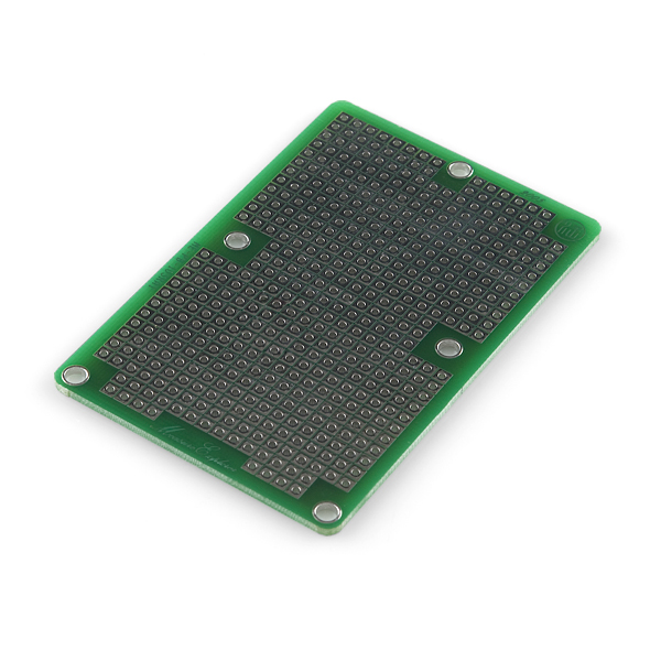
A basic double sided perf board with a copper pour available for a power or ground plane. Wire your circuit like normal with point to point wiring, and if you need to connect a pin to the copper pour, simply add some extra solder to the joint and jumper to the plane. Standard 0.1" spacing with a 4-40 (3mm) holes for mounting. Great for quickly prototyping stackable circuits.
ProtoBoard - Rectangle 3" Product Help and Resources
RedBoard Santa Trap
December 25, 2014
A fun holiday project to try for anyone looking to catch Santa on Christmas!
Core Skill: Soldering
This skill defines how difficult the soldering is on a particular product. It might be a couple simple solder joints, or require special reflow tools.
Skill Level: Noob - Some basic soldering is required, but it is limited to a just a few pins, basic through-hole soldering, and couple (if any) polarized components. A basic soldering iron is all you should need.
See all skill levels
Comments
Looking for answers to technical questions?
We welcome your comments and suggestions below. However, if you are looking for solutions to technical questions please see our Technical Assistance page.
Customer Reviews
4 out of 5
Based on 1 ratings:
Solid, but careful with the ground plane
Plated thru holes and a solid board. One side has a ground plane surrounding the holes, which does not prevent a successful solder, but one does have to careful. The plus side is the ground plane helps keep the noise level down, and makes the numerous connections to ground easy. I do most of my connections with wirewrap, so that minimizes my soldering. It fits nicely in the SparkFun Projects Case - Clear with room to spare for DC/DC converter and connectors.
Would anyone mind explaining the basic/typical usage for these double-sided protoboards?
It seems obvious to me (a newbie) that the square pads make up the 'under side' of the board, and that my components would be laid out on the side with the ground plane, correct? How is the ground plane used then? Do I solder bridge a 'top side' connection from the ground plane to one of holes so that the corresponding pad underneath becomes ground?
Also, it is easier to solder the odd SMD part to the board between rectangular pads, if you're mixing SMD/PTH parts. Sometimes, you just cannot avoid that.
You use the pads to solder the components into place, then use wires or component leads to make the connections. Solder bridges can get ugly.
sigh I wish I had read 'solder bridges can get ugly' earlier before I started :P
Oh well.
Oh my glob!!! Retired?!?1 Please bring these back; they're hands-down the best perf boards I've ever used. I love the ground plane, I love the square pads, and this is a perfect size. Even if you could just release the design, I'm happy to order them from a pcb manufacturer. These make me twice as fast when making protoboards.
Unfortunately, these were not an in-house design, so we don't have the Eagle files. However, the manufacturer part number is: ME-PB-103RAI, so hopefully that will be of some help for you.
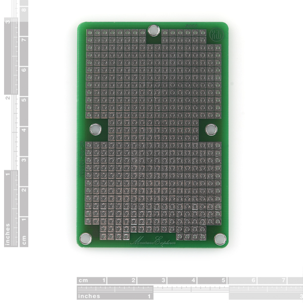
My estimate of the hole coordinates in mm: [x,y] [3.0, 3.0] [48, 3.0] [6.4, 39] [44.5, 39], [25.5, 72]. It would be great if Sparkfun could provide the official numbers.
I am ordering parts.
Did I order the parts?
past you said you were - why is present you doubting them? - future you may wish to double-check by going to your order history :)
Someone tell me how you’re supposed to use this… I think I need one but I don’t know how to use these.
As with the breadboard, your first stop should perhaps be: wikipedia: stripboard
Basically, once you've got your circuit completed on a breadboard and want to give it a more permanent installation - but don't want to design your own PCB - you'd move the components over to one of these (possibly cutting it down to the size you need) and solder them down, recreating the circuit by creating solder bridges (basically enough solder between 2 pads that they end up being connected), wires, and - where needed - cutting traces.
There are a great number of these types protoboards (stripboard as wikipedia prefers), and they each have theirs pros and cons. This one, for example, has a 'plane' on one side that you could solder a component to for a commonly used connection like the ground (just like you may design a PCB yourself with a ground plane). The down side here is that the planes goes everywhere and you may easily create solder bridges you don't want. It's also smaller than, say, the ProtoBoard Wombat, meaning you can't cut as many smaller boards out of this one - but the Wombat doesn't have the plane. The ProtoBoard - Round 4" - 'Stadium' which you also asked about is obviously a different shape, but also offers 3 holes per pad, meaning you have to create fewer solder bridges/wire connections. I'm partial to 3-hole-pads myself, but in a different configuration not on offer from SparkFun - but it really tends to come down to personal preference.
Do they come in red ?
Can anyone give accurate dimensions for this product? I need the length, width, mounting hole size, and mounting hole positions.
What's the hole size?
I wish this had mounting holes on each corner, instead of the 5-hole arrangement. Oh well, the 4" round one will work for my purposes.
or half a wombat (?. whatever the large PTH protoboard is named)
You stick an IC in, then put a wire into the hole next to a pin and bend the wire over to the pin and solder it on to make the connection. You can do something similar with other through-hole components like LEDs and resistors by bending the leads over to an adjacent hole before snipping them. Trying to get solder to bridge the gap by itself is a huge pain in the ass and not a good way of doing it.
so help me out here if you don't mind .. . . is the idea that you solder everything on the "isolated square" side, and only poke the pins that you want grounded through the hole, and solder to the ground-plane?
Which I think means I'd need to either bend pins horizontally to prevent them sticking through, or keep things like DIP sockets raise so pins don't protrude though the holes.
scratch that.
Eyes aren't what they used to be. I see now that each square pad is isolated not only from the square pads, but that nothing is connected to the ground-plane unless you connect it yourself.
Doh!
I use these for quick Arduino proto shields. A couple of rows wider and they would be a perfect fit - as it is I prefer them to the other proto shields available because of the amount of real estate they provide.
Note that bridging adjacent cells is not a simple task without a bit of wire - the cells REALLY like to stay isolated. This is extremely nice for prototyping as it helps to eliminate inadvertent shorts, but can be frustrating when you actually WANT to short adjacent cells .
You could try using one of those conductive ink pens. You just draw a line between the pads, then solder stuff in. They're pretty cool, you can even repair broken heater traces on your car window!
These plated through hole proto boards are awesome compared to regular single sided perf board. The small gaps and square pads make it a lot easier to make your bridges and/or wire traces. The solder flows a lot easier than on single sided cheap stuff.
I'll definitely be keeping my lab stocked with a couple of these at any one time.
Is the idea with protoboards like this to actually create solder bridges to adjacent pads, or to just put wires in the holes with pins from components?
The idea is you stick, say, an IC in, put say, a wire in the adjacent pad and create a small solder bridge between the two. It's hard to stick 2 wires in one hole. Believe me.
This will fit on the Universal Plate from Tamiya, right? And I only have to solder on one side?
2 Words: Never. Mind.