- Home
- Product Categories
- Audio
- SparkFun Mic Preamp

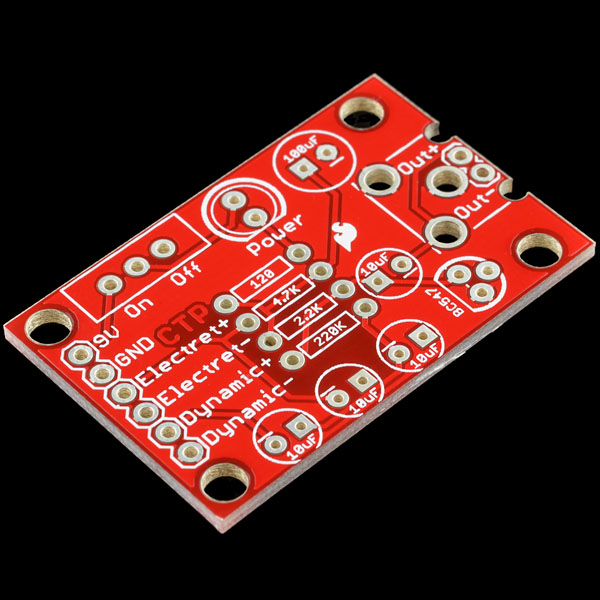
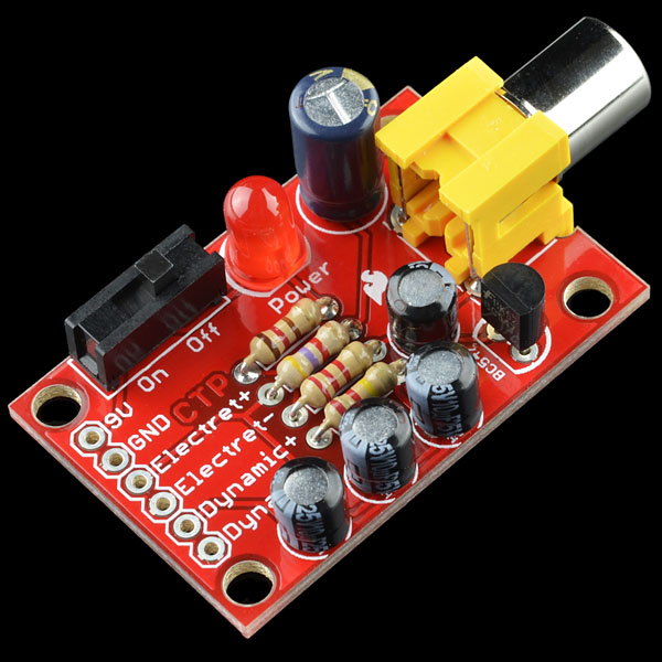
SparkFun Mic Preamp
This is a simple microphone preamplifier circuit for a wide range of microphone types, with good pre-amplification to attach to your larger stereo amplifier. This circuit is suitable for use with normal stereo amplifier line/CD/aux/tape inputs. The microphone preamplifier works great with guitar pickups, piezo disks, and can take both dynamic and electret microphone inputs (preamplifier provides power for electret microphone elements). This is a simple, easy to build circuit that is flexible and very handy when working with microphones and amplifiers.
**Board does not come assembled. **You will need to purchase the components separately, check the related items at the bottom of the page for available components. Also, reference the schematic for the BOM.
- Very simple one transistor circuit
- Amplification 35 dB, flat frequency response from 20 Hz to 20 kHz
- Low distortion but certainly not studio quality
- Interface dynamic or electret microphone to a line level audio input in HIFI amplifier or computer soundcard
- Power supply: 9V battery, takes less than 10 mA current
- No special protection circuits used
- No special electrical safety considerations
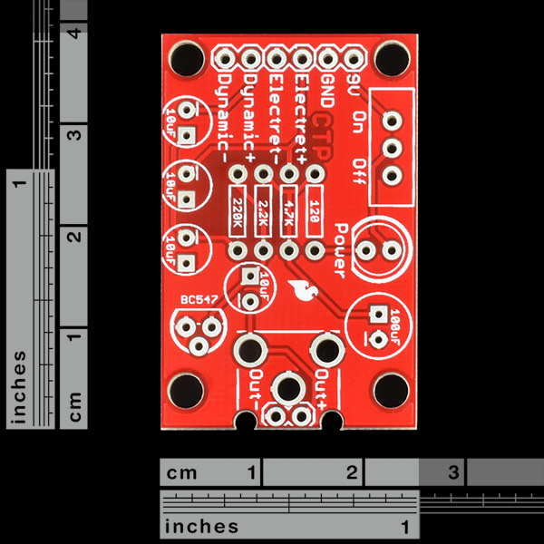
- 1"x1.5"x0.6"
- Schematic
- Eagle Files
- GitHub (Design Files)
SparkFun Mic Preamp Product Help and Resources
Core Skill: Soldering
This skill defines how difficult the soldering is on a particular product. It might be a couple simple solder joints, or require special reflow tools.
Skill Level: Rookie - The number of pins increases, and you will have to determine polarity of components and some of the components might be a bit trickier or close together. You might need solder wick or flux.
See all skill levels
Comments
Looking for answers to technical questions?
We welcome your comments and suggestions below. However, if you are looking for solutions to technical questions please see our Technical Assistance page.
Customer Reviews
No reviews yet.
Why isn't this a kit?
Is there still an issue with the RCA jack? I just put this together but can't get an output from it whatsoever.
I don't see the BOM anywhere. Can someone point me to where that is?
Well, you can interpret the BOM manually.
Here's the BOM as far as I can tell:
.
The following are not available as separate products from SFE, and the current Resistor Kit - 1/4W (500 total) does not include all required values. If you are picking up components elsewhere, they're sure to have them. If not - hit any of the popular online auction sites and look for an E12 series kit. You'll have enough resistors to last you a long time and with good coverage of values. Note that SFE's kit will work if you're willing to substitute values, but doing so is likely to affect the characteristics of the amplifier; putting resistors in series/parallel will, of course, also work - but e.g. the 220kΩ resistor would require 3 resistors from the SFE kit. If you do want to try different values, I'd recommend setting the circuit up on a breadboard first to check how each change influences the output.
.
Lastly, the jack depicted. See comments on why you may wish to forego placing this directly on the board - in which case you may wish to choose a different jack type as well.
.
You'll additionally need something to connect your microphone to the board..
Why an RCA jack?
Hello, I am new on "Sparkfun"! I had bought two of these to use to power a stereo electret mic that I have. Can I combine the two tying the grounds and positives together on the same power source? If not that way ; Is there another way to do it so I can run it in stereo mode? Thank you in advance!!!
I had to chime in here... This preamp is exactly what I needed! I've been messing around with APR9600, ISD1720, ISD1730 and ISD17240 IC modules that allow you to record voice on a chip, with most of the functionality handled by the IC. I used an electret microphone with all these voice recording modules, but found that unless I was talking right into the electret mic, the voice signal was mostly lost.
I tried using LM386-based amplifiers to boost my already-recorded recordings (as well as a Velleman 7W amplifier kit from Amazon), and while these amplifiers worked, I was mostly amplifying the ambient room noise from during the recording.
Using this microphone pre-amp solved my low voice signal problem prefectly! I ordered one of these PCBs (no, they don't give you any parts but the PCB), added a few resistors, capacitors and jumpers/headers, an LED, a BC547 transistor and a switch, and soldered it up. I put the electret microphone I had been using for the voice-recording modules on the pre-amp, and hooked the pre-amp output to the input of the voice-recording module. It worked immediately, and amplified the voice recording to a very acceptable level, saving it to the voice-recording module.
One caveat I found (which could certainly be related to the ISD17240 IC module I used for my final recording device), was that the pre-amp worked best for me at somewhere around 4-5 Vdc (instead of 9V as per spec.) As I raised the voltage on the pre-amp toward 9V the pre-amplification effect decreased instead of increasing. I'm sure someone can tell us why this is so, but it works out great for me as this is the voltage of my ISD17240 IC module as well.
Note: As one other user mentioned that the RCA jack PCB hookup was defective (at some point 3 years ago), I did not bother using a jack, and instead used the Out+ and Out- for the output from the pre-amp. This may be fixed by now, but I did not use it...
I haven't try the circuit, but R4 (220k ohm) seems too small for 9V supply. I'd increase it to may be 470k or even higher. You can see if you have the best value by reading the voltage at the Q1 collector. The voltage here should be about 3-4.5V when you don't have the sound coming in.
Since the LED is in series with R4, it works out. I just tested my circuit, and with 9V input, the Q1 collector is right at 3V.
Could something like this be used for making a record player (phono) preamp? Could you use the INA217 chip mentioned in the $5 preamp link above to make a phono preamp? Or would the amplifier kit that's sold on Sparkfun for ~$30 be the thing I'd want to look into?
I recently got a new receiver that does not have a built-in phono input. I could buy a preamp for the turn table, but I thought it would be fun to try to build one.
Thanks!
I am David Mellor, author of the original article on the $5 preamp. The article, with followups and comments, is now available here...
www.audiomasterclass.com/?a=588
Dave, where can I find this article now, 2/19/13?
In case David is out, try: http://nolimitsoundproductions.blogspot.com/2012/04/famous-5-preamp-everything-you-need-to.html or just hit up google for 'david mellor $5 pre-amp' (no quotes) to find individual articles and further discussion.
Can anyone provide some advice on modifying this circuit to work with a 12V power source?
You can use an LM7809 linear voltage regulator power supply circuit to drop that 12V down to a clean 9V out. Should only need an electrolytic and ceramic input filter capacitors and an electrolytic output capacitor for the regulator to run properly.
Interesting. Why not make a "studio quality" version with the Texas Instruments INA217:
"Fresh from a comparison test against preamps costing $200 and $1500 - which it beat handsomely - the secrets of the $5 preamp are at last revealed."
http://www.audiomasterclass.com/arc.cfm?a=giant-killing-%245-mic-preamp-its-secrets-revealed
Hi GlennPowers, did you use a Texas Instruments INA217 together with this mic pre amp circuit board?
thanls
I'm pretty sure this board has a design flaw such that the inner and outer conductors of the RCA jack are shorted. I alerted SparkFun, and they are supposedly working on a fix.
The board still works using the .1" spaced Out+ and Out- signals (don't solder the RCA jack).
Also, I found that it operates pretty well on Li-ion voltage.
The BOB-08669 is smaller but amplifies high frequencies too much. This board (even at 3.7 v) has better balance.